2018 MERCEDES-BENZ SLC ROADSTER clock
[x] Cancel search: clockPage 132 of 298
!Overfilling the fuel tank could damage the
fuel system.
!Take care not to spill any fuel on painted
surfaces. You could otherwise damage the
paintwork.
!Use afilter when adding fuel from afuel can.
The fuel lines and/or the fuel injection system
could otherwise be blocked by particles from
the fuel can.
If you overfill the fuel tank, fuel could spray out
when the fuel pump nozzle is removed.
For further information on fuel and fuel quality
(
Ypage 291).
Refueling
General information
The fuel filler flap is unlocked or locked auto-
matically when you unlock or lock the vehicle
with the SmartKey or using KEYLESS-GO.
The position of the fuel filler cap is displayed
8 in the instrument cluster. The arrow next
to the filling pump indicates the side of the vehi-
cle.
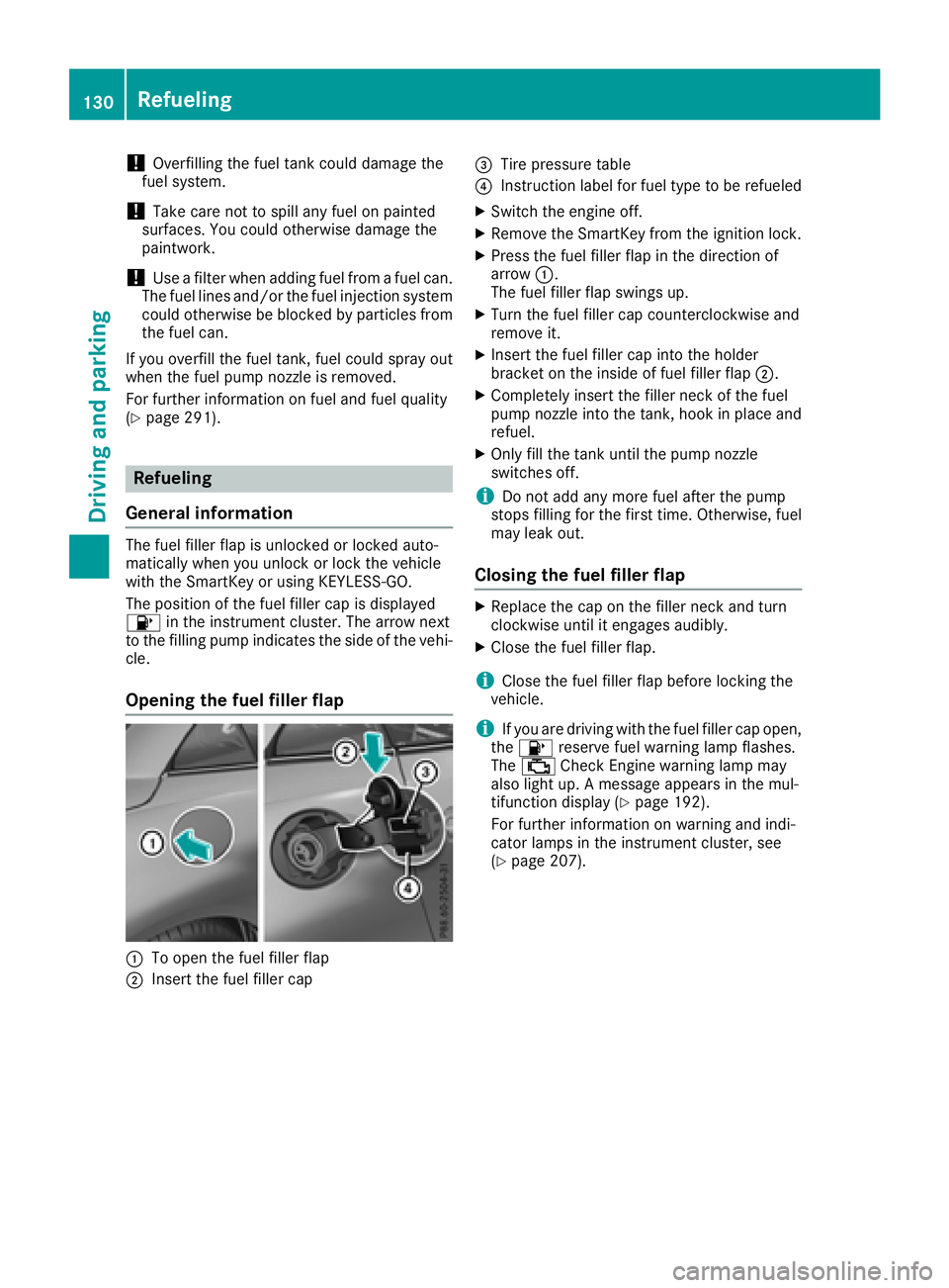
Opening the fuel filler flap
:To open the fuel filler flap
;Insert the fuel filler cap
=Tire pressure table
?Instruction label for fuel type to be refueled
XSwitch the engine off.
XRemove the SmartKey from the ignition lock.
XPress the fuel filler flap in the direction of
arrow :.
The fuel filler flap swings up.
XTurn the fuel filler cap counterclockwise and
remove it.
XInsert the fuel filler cap into the holder
bracket on the inside of fuel filler flap ;.
XCompletely insert the filler neck of the fuel
pump nozzle into the tank, hook in place and
refuel.
XOnly fill the tank until the pump nozzle
switches off.
iDo not add any more fuel after the pump
stops filling for the first time. Otherwise, fuel
may leak out.
Closing the fuel filler flap
XReplace the cap on the filler neck and turn
clockwise until it engages audibly.
XClose the fuel filler flap.
iClose the fuel filler flap before locking the
vehicle.
iIf you are driving with the fuel filler cap open,
the 8 reserve fuel warning lamp flashes.
The ; Check Engine warning lamp may
also light up. Amessage appears in the mul-
tifunction display(
Ypage 192).
For further information on warning and indi-
cator lamps in the instrument cluster, see
(
Ypage 207).
130Refueling
Driving and parking
Page 165 of 298
Important safety notes
GWARNING
If you operate information systems and com-
munication equipmen tintegrate dinthevehi-
cle when driving ,you may be distracte dfrom
th et raffic situation .You could also lose con-
trol of th evehicle. Ther eisariskofana cci-
dent.
Only operate this equipmen twhen th etraffic
situation permits. If you are no tsuret hatthis
is possible ,park th evehicl epayin gattention
to traffic condition sand operate th eequip-
men twhen th evehicl eiss tationary.
You must observ ethe legal requirements for th e
country in whic hyou are currentl ydriving when
operating th eon-bo ard computer.
GWARNIN G
If th einstrumen tcluste rhas faile dormal-
functioned, you may no trecognize function
restriction sinsystems relevan ttosafety. The
operating safet yofyour vehicl emay be
impaired .Ther eisar iskofana ccident.
Drive on carefully. Hav ethe vehicl echecked
at aq ualified specialist workshop immedi-
ately.
The on-board computer only shows message sor
warning sfromc ertai nsystems in th emultifunc-
tion display. You should therefor emakes ure
your vehicl eisoperating safely at all times .
If th eoperating safet yofyour vehicl eis
impaired ,pull ove rassoonasitiss afetodos o.
Contac taqualified specialist workshop.
Fo rano verview, see th einstrumen tpanel illus-
tration (
Ypage 32).
Display sand operation
Instrumen tcluster lighting
The lighting in th einstrumen tcluster, in th edis-
plays and th econtrols in thevehicl einterior can
be adjusted usin gthe brightness control knob.
The brightness control knob is locate donthe
botto mleftoft heinstrumen tcluste r
(
Ypage 32).
XTurn th ebrightness control knob clockwise or
counter-clockwise.
If you tur nthe ligh tswitch (
Ypage 95 )tot he
Ã, TorL position ,the brightness
will depend upon th ebrightness of th eambi -
en tlight.
The ligh tsensor in th einstrumen tcluste r
automatically control sthe brightness of th e
multifunction display. In daylight, th edisplays
in th einstrumen tcluste rare no tilluminated.
Speedometer with segments
The segments in th espeedometer indicat e
whic hspee drange is available.
RCruis econtro lactivated (Ypage 138):
The segments ligh tupfromt hestore dspee d
to th emaximum speed.
RDistanc ePilot DISTRONI Cisactivated
(Ypage 140):
On eort wo segments in th eset spee drange
ligh tup.
RDistanc ePilot DISTRONI Cdetects avehicl ein
fron tmoving mor eslowly than th estored
speed:
The segments between th espee doft hevehi-
cle in fron tand th estoreds pee dligh tup.
Tachometer
!
Do no tdriveint heoverrevving range, as this
could damag ethe engine.
The red ban dinthetachometer indicates th e
engine's overrevving range.
The fuel suppl yisinterrupted to protect th e
engin ewhen th ered ban disreached.
Outsidet emperatur edisplay
You should pay special attention to road condi-
tion swhen temperatures are aroun dfreezing
point.
Bea rinm indt hatthe outside temperature dis-
play indicates th etem perature measured and
does no trecord th eroad temperature.
The outside temperature display is in th emulti-
function display (
Ypage 165).
Ac hang eint heoutside temperature is shown in
th em ultifunction display after adelay.
Display sand operation163
On-boardc omputer and displays
Z
Page 176 of 298
XPress the:or9 button to select the
Automatic Door Lockfunction.
When the Automatic Door Lockfunction is
activated, the multifunction display shows the
left-hand vehicle door in orange.
XPress the abutton to save the setting.
For further information on the automatic locking
feature, see (
Ypage 71).
Activating/deactivating the acoustic
locking verification signal
If you switch on the AcousticLockfunction, an
acoustic signal sounds when you lock the vehi-
cle.
XPress the =or; button on the steering
wheel to select the Sett.menu.
XPress the:or9 button to select the
Vehiclesubmenu.
XPress ato confirm.
XPress the :or9 button to select the
Acoustic Lockfunction.
If the Acoustic Lockfunction is activated,
the & symbol in the multifunction display
lights up orange.
XPress the abutton to save the setting.
Comfort
Activating/deactivating the EASY-
ENTRY/EXITf eature
GWARNING
When the EASY-ENTRY/EXIT feature adjusts
the steerin gwheel, you and other vehicle
occupants–p articularly children –could
become trapped. There is arisk of injury.
While the EASY-ENTRY/EXIT feature is mak-
ing adjustments, make sure that no one has
any body parts in the sweep of the steering
wheel.
If somebody becomes trapped:
Rpress one of the memory function position
buttons, or
Rmove the switch for steerin gwheel adjust-
ment in the opposite direction to that in
which the steerin gwheel is moving.
The adjustmen tprocess is stopped.
XPress the =or; button on the steering
wheel to select the Sett.menu.
XPress the:or9 button to select the
Conveniencesubmenu.
XPress ato confirm.
XUsing :or9,s elect the EasyEntry/Exitfunction.
If the EasyEntry/Exitfunction is activated,
the multifunction display shows the steering
wheel in orange.
XPress the abutton to save the setting.
Further information on the EASY-ENTRY/EXIT
feature (
Ypage 89).
Switching the seat belt adjustment on/off
XPress the =or; button on the steering
wheel to select the Sett.menu.
XPress the:or9 button to select the
Conveniencesubmenu.
XPress ato confirm.
XPress the :or9 button to select the
Belt Adjustmentfunction.
When the Belt Adjustmentfunction is acti-
vated, the seat belt is displayed in orange in
the multifunction display.
XPress the abutton to save the setting.
For further information on belt adjustment, see
(
Ypage 42).
Switching the fold-in mirrors when lock-
ing feature on/off
This function is only availablew hen the vehicle is
equipped with the electrical fold-in function.
This function is only availableinC anada.
When you activat ethe Auto.
MirrorFoldingfunction, the exterior mirrors are folded in when
the vehicle is locked.
If you have switched on the Auto. Mirror
Foldingfunction and you fold in the exterior
mirrors using the button on the door
(
Ypage 91), they will not fold out automatically.
The exterior mirrors can then only be folded out
using the button on the door.
XPress the =or; button on the steering
wheel to select the Sett.menu.
XPress the:or9 button to select the
Conveniencesubmenu.
XPress ato confirm.
174Menus and submenus
On-board computer and displays
Page 237 of 298
XPull out oil dipstick:.
XWipe off oil dipstick :.
XSlowly slide oil dipstick :into the guide tube
to the stop, and take it out again.
If the level is between MIN mark =and MAX
mark ;,the oil level is correct.
XIf the oil level has dropped to MIN mark =or
below, add 1.1 US qt (1.0 liter) of engine oil.
Adding engine oil
GWARNING
Certain components in the engine compart-
ment ,such as the engine, radiator and parts
of the exhaust system, can become very hot.
Workingint he engine compartment poses a
risk of injury.
Where possible, let the engine cool down and touch only the components described in the
following.
GWARNING
If engine oil comes into contact with hot com- ponentsint he engine compartment ,itmay
ignite. There is arisk of fire and injury.
Make sure that engine oil is not spilled next to
the filler neck.L et the engine cool down and
thoroughly clean the engine oil off the com-
ponentsb efore starting the engine.
HEnvironmenta lnote
When adding oil, take care not to spill any. If
oil enter sthe soil or waterways, it is harmful to
the environment.
!Use only engine oils and oil filters that are
approved for vehicles with aservice system. A
list of the engine oils and oil filters that have
been tested and approved in accordanc ewith
Mercedes-Benz Specifications for Service
Products is availableata ny authorized
Mercedes-Benz Center. The following cause engine failure or damage
to the exhaust system:
RUse of engine oils and oil filters that have
not been expressly approved for the service
system
RReplacement of engine oil and oil filter after
the replacement interval specified by the
service system has expired
RUse of engine oil additives
!Do not add too much oil. If the oil level is
above the "max" mark on the dipstick ,too
much oil has been added. This can lead to
damage to the engine or the catalytic con-
verter .Have excess oil siphoned off.
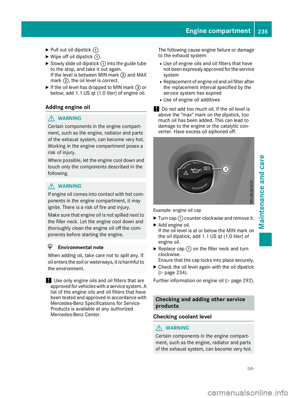
Example: engine oil cap
XTurn cap :counter-clockwise and remove it.
XAdd engine oil.
If the oil level is at or below the MIN mark on
the oil dipstick ,add 1.1 US qt (1.0 liter) of
engine oil.
XReplace cap :on the filler neck and turn
clockwise.
Ensure that the cap locks into place securely.
XCheck the oil level again with the oil dipstick
(Ypage 234).
Further information on engine oil (
Ypage 292).
Checking and adding other service
products
Checking coolant level
GWARNING
Certain components in the engine compart-
ment ,such as the engine, radiator and parts
of the exhaust system, can become very hot.
Engine compartment235
Maintenance and care
Z
Page 238 of 298
Workinginthe engine compartment poses a
risk of injury.
Where possible, let the engine cool down and touch only the componentsd escribed in the
following.
GWARNING
The cooling system is pressurized, particularly
when the motor is warm. If you open the cap,
you could be scalded if hot coolant sprays out.
There is arisk of injury.
Let the engine cool down before you open the
cap. Wear gloves and eye protection. Slowly
open the cap to relieve pressure.
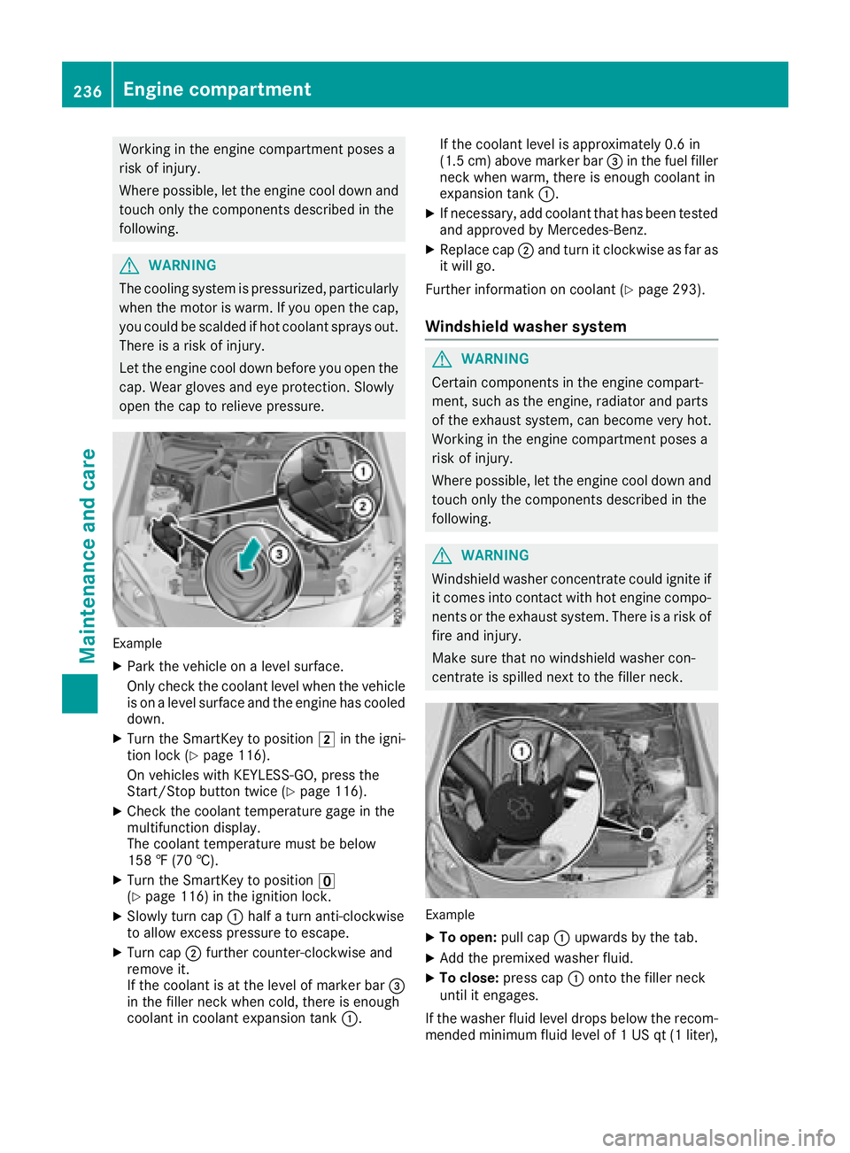
Example
XPark the vehicle on alevel surface.
Only check the coolant level when the vehicle
is on alevel surface and the engine has cooled
down.
XTurn the SmartKey to position 2in the igni-
tion lock (Ypage 116).
On vehicles with KEYLESS-GO, press the
Start/Stop button twice (
Ypage 116).
XCheck the coolant temperature gage in the
multifunction display.
The coolant temperature must be below
158 ‡(70 †).
XTurn the SmartKey to position u
(Ypage 116) in the ignition lock.
XSlowly turn cap :half aturn anti-clockwise
to allow excessp ressure to escape.
XTurn cap;further counter-clockwise and
remove it.
If the coolant is at the level of marker bar =
in the filler neck when cold, there is enough
coolant in coolant expansion tank :.If the coolant level is approximately 0.6 in
(1.5 cm
)above marker bar =in the fuel filler
neck when warm, there is enough coolant in
expansion tank :.
XIf necessary, add coolant that has been tested
and approved by Mercedes-Benz.
XReplace cap;and turn it clockwise as far as
it will go.
Further information on coolant (
Ypage 293).
Windshield washer system
GWARNING
Certain component sinthe engine compart-
ment,s uch as the engine, radiator and parts
of the exhaust system, can become very hot.
Workin ginthe engine compartment poses a
risk of injury.
Where possible, let the engine cool down and touch only the componentsd escribed in the
following.
GWARNING
Windshield washer concentrate could ignite if it comes into contact with hot engine compo-
nents or the exhaust system. There is arisk of
fire and injury.
Make sure that no windshield washer con-
centrate is spilled next to the filler neck.
Example
XTo open: pull cap:upwards by the tab.
XAdd the premixed washer fluid.
XTo close: press cap :ontothe filler neck
until it engages.
If the washer fluid level drops below the recom-
mended minimum fluid level of 1USqt(1l iter),
236Engine compartment
Maintenance and care
Page 254 of 298
rubbish. They must be col-
lected separately and dis-
posed of in an environmen-
tallyresponsible recycling
system.
Dispose of batterie sinan
environmentally responsi-
ble manner. Take dis-
charge dbatterie stoaq uali-
fied specialist workshop or
to ac ollection point for
used batteries.
!Have the battery checked regularl yata
qualified specialist workshop.
Observe the service interval sinthe Mainte-
nance Booklet or contact aqualified specialist
workshop for more information.
!Always have work on batterie scarrie dout at
aq ualified specialist workshop.
Shoul dit, in exceptionalc ircumstances, be
absolutel ynecessary to disconnect the 12-
volt battery yourself, please observe the fol-
lowing:
RSecure the vehicletop revent it from rolling
away.
RSwitch off the ignition.
RDisconnect the negative terminal first and
then the positive terminal.
The transmission is locked in position j
after disconnecting the battery.
After the work has been done, install the bat- tery and replace the cover of the positive ter-
minal clamp firmly.
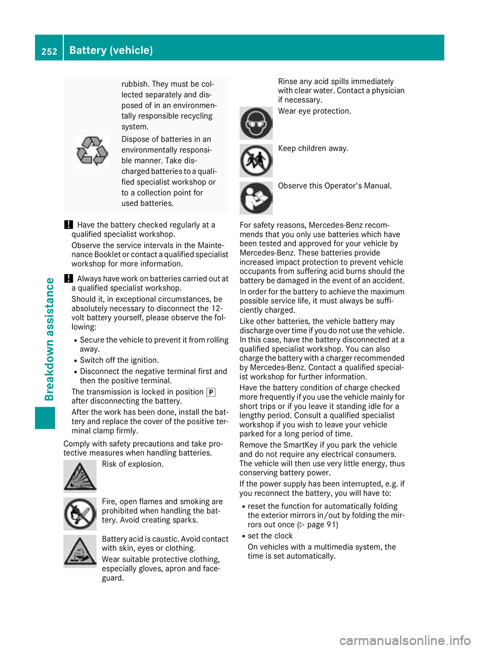
Comply with safety precautions and take pro-
tective measures when handling batteries.
Ris kofe xplosion.
Fire, open flame sand smoking are
prohibited when handling the bat-
tery. Avoid creating sparks.
Battery acid is caustic. Avoid contact
with skin, eye sorclothing.
Wears uitable protective clothing,
especially gloves, apro nand face-
guard. Rinse any acid spills immediately
with clearw
ater. Contact aphysician
if necessary.
Weare ye protection.
Keep children away.
Observe this Operator's Manual.
For safety reasons, Mercedes-Benz recom-
mends that you only use batterie swhich have
been tested and approved for you rvehicleb y
Mercedes-Benz. These batterie sprovide
increase dimpact protection to prevent vehicle
occupants from suffering acid burns should the
battery be damaged in the event of an accident.
In order for the battery to achieve the maximum
possible service life,itm ust alwaysbesuffi-
ciently charged.
Like other batteries, the vehicleb attery may
discharge over time if you do not use the vehicle.
In this case, have the battery disconnected at a
qualified specialist workshop.Y ou can also
charge the battery with acharge rrecommended
by Mercedes-Benz. Contact aqualified special-
ist workshop for further information.
Have the battery condition of charge checked
more frequently if you use the vehiclem ainlyfor
short trips or if you leave it standing idlef or a
lengthy period. Consult aqualified specialist
workshop if you wis htoleave you rvehicle
parked for along periodoft ime.
Remove the SmartKey if you park the vehicle
and do not require any electricalc onsumers.
The vehiclew illt hen use very little energy,t hus
conserving battery power.
If the powers upply has been interrupted ,e.g. if
you reconnect the battery ,you wil lhave to:
Rreset the function for automatically folding
the exterior mirrors in/out by folding the mir-
rors out once (
Ypag e91)
Rset the clock
On vehicles with amultimedia system, the
time is set automatically.
252Battery (vehicle)
Breakdown assistance
Page 259 of 298
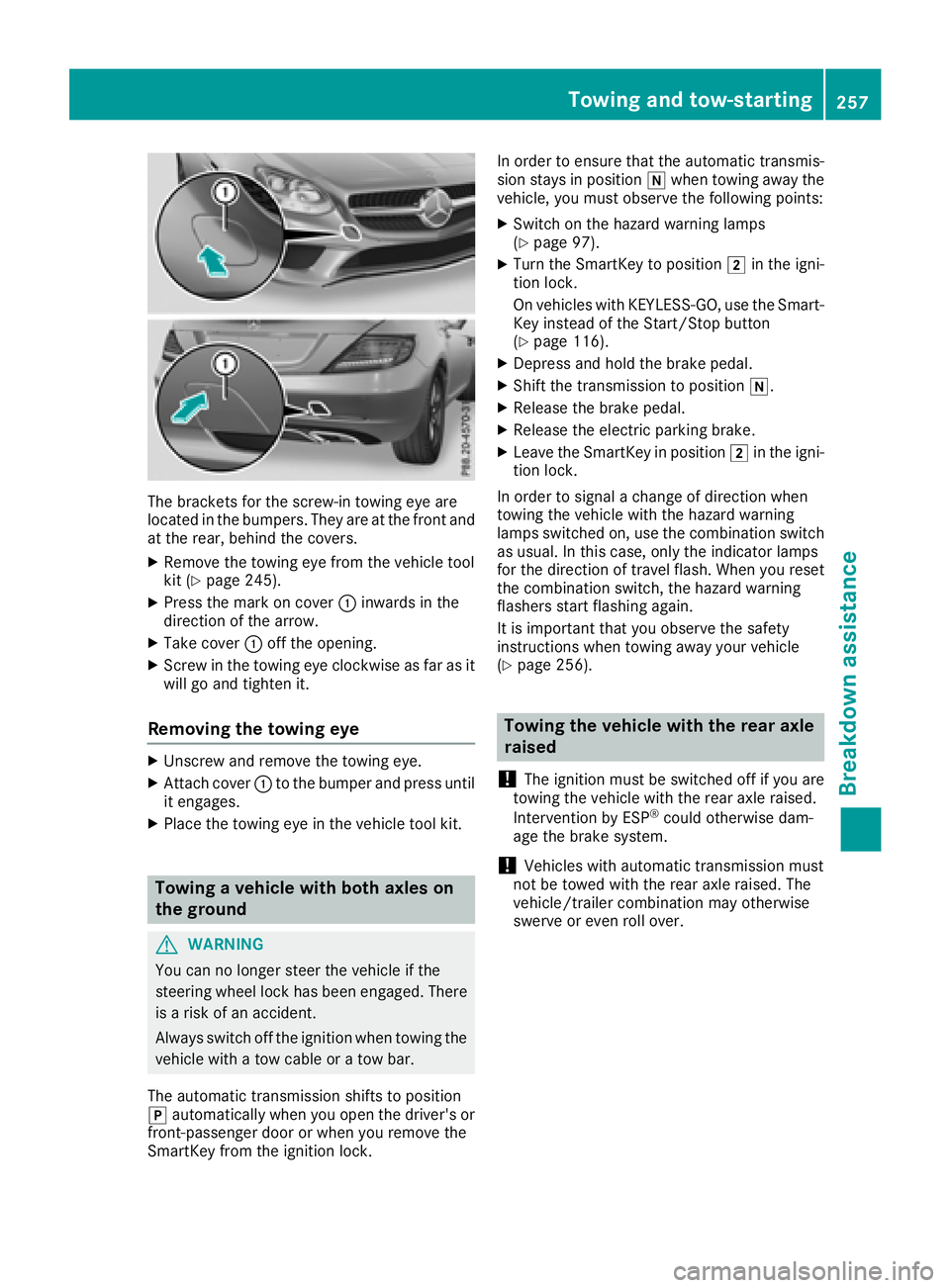
The bracketsfor the screw-in towing eye are
located in the bumpers. They are at the front and
at the rear, behind the covers.
XRemove the towing eye from the vehicle tool
kit (Ypage 245).
XPress the mark on cover :inwards in the
direction of the arrow.
XTake cover :off the opening.
XScrew in the towing eye clockwise as far as it
will go and tighten it.
Removing the towing eye
XUnscrew and remove the towing eye.
XAttach cover :to the bumper and press until
it engages.
XPlace the towing eye in the vehicle tool kit.
Towing avehicle with both axles on
the ground
GWARNING
You can no longer steer the vehicle if the
steerin gwheel lock has been engaged. There
is ar isk of an accident.
Always switch off the ignition when towing the
vehicle with atow cable or atow bar.
The automatic transmission shifts to position
j automatically when you open the driver's or
front-passenger door or when you remove the
SmartKey from the ignition lock. In order to ensure that the automatic transmis-
sion stays in position
iwhen towing away the
vehicle, you must observe the following points:
XSwitch on the hazard warning lamps
(Ypage 97).
XTurn the SmartKey to position 2in the igni-
tion lock.
On vehicles with KEYLESS-GO, use the Smart-
Key instead of the Start/Stop button
(
Ypage 116).
XDepress and hold the brake pedal.
XShift the transmission to position i.
XRelease the brake pedal.
XRelease the electric parking brake.
XLeave the SmartKey in position2in the igni-
tion lock.
In order to signal achange of direction when
towing the vehicle with the hazard warning
lamps switched on, use the combination switch
as usual. In this case, only the indicator lamps
for the direction of travel flash. When you reset
the combination switch, the hazard warning
flashers start flashing again.
It is important that you observe the safety
instructions when towing away your vehicle
(
Ypage 256).
Towing the vehicle with the rear axle
raised
!
The ignition must be switched off if you are
towing the vehicle with the rear axle raised.
Intervention by ESP
®could otherwise dam-
age the brake system.
!Vehicles with automatic transmission must
not be towed with the rear axle raised. The
vehicle/trailer combination may otherwise
swerve or even roll over.
Towing and tow-starting257
Breakdown assistance
Z
Page 285 of 298
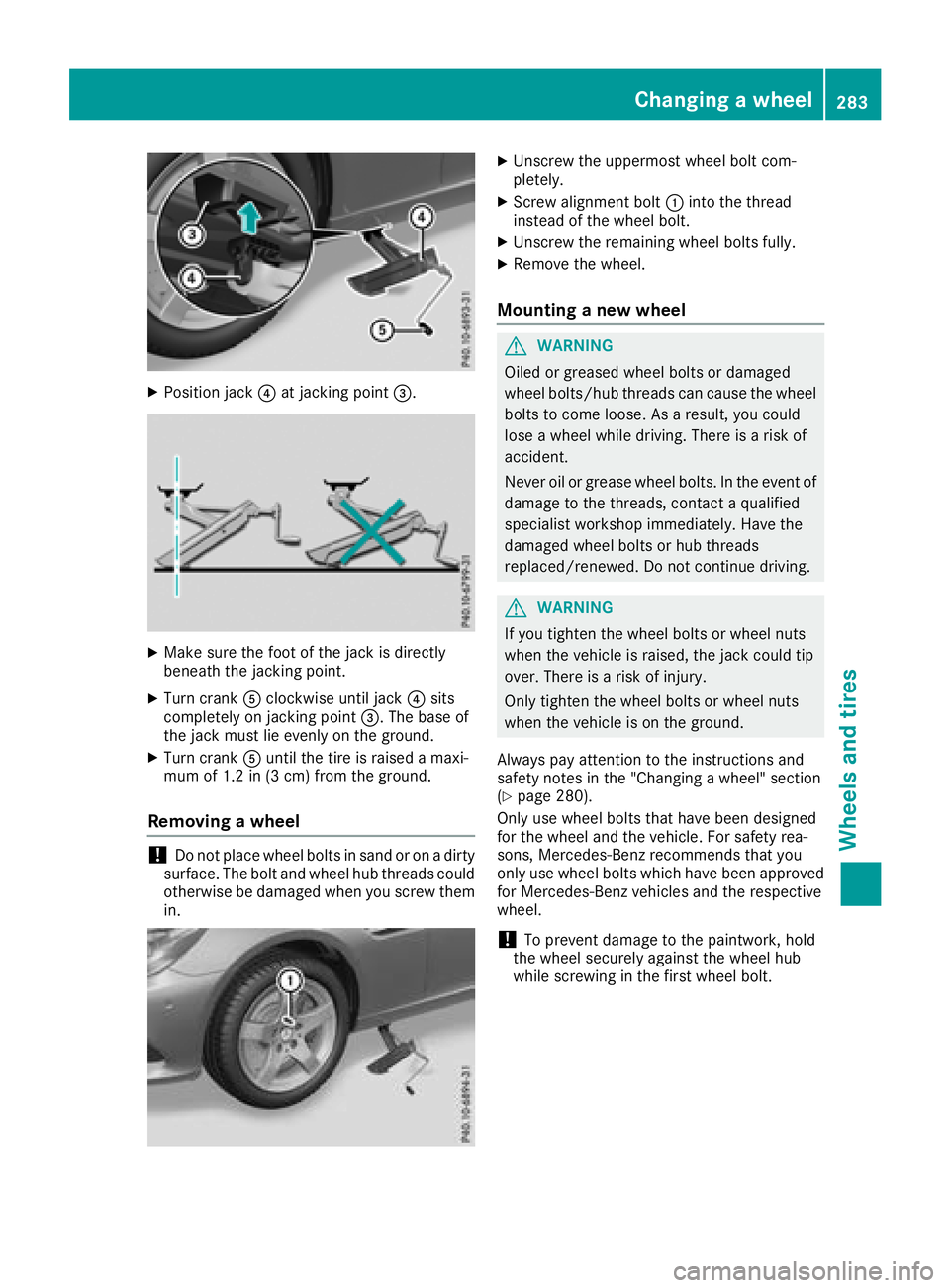
XPosition jack?at jacking point =.
XMake sure the foot of the jack is directly
beneath the jacking point.
XTurn crankAclockwise until jack ?sits
completely on jacking point =.The base of
the jack must lie evenly on the ground.
XTurn crank Auntil the tire is raised amaxi-
mum of 1.2 in (3 cm) from the ground.
Removing awheel
!Do not place wheel bolts in sand or on adirty
surface. The bolt and wheel hub threads could
otherwise be damaged when you screw them
in.
XUnscrew the uppermost wheel bolt com-
pletely.
XScrew alignment bolt :into the thread
instead of the wheel bolt.
XUnscrew the remaining wheel bolts fully.
XRemove the wheel.
Mounting anew wheel
GWARNING
Oiled or greased wheel bolts or damaged
wheel bolts/hub threads can cause the wheel bolts to come loose. As aresult, you could
lose awheel while driving. There is arisk of
accident.
Never oil or grease wheel bolts. In the event of
damage to the threads, contact aqualified
specialist workshop immediately. Have the
damaged wheel bolts or hub threads
replaced/renewed. Do not continue driving.
GWARNING
If you tighten the wheel bolts or wheel nuts
when the vehicle is raised, the jack could tip
over. There is arisk of injury.
Only tighten the wheel bolts or wheel nuts
when the vehicle is on the ground.
Always pay attention to the instruction sand
safety notes in the "Changing awheel" section
(
Ypage 280).
Only use wheel bolts that have been designed
for the wheel and the vehicle. For safety rea-
sons, Mercedes-Benz recommends that you
only use wheel bolts which have been approved for Mercedes-Benz vehicles and the respective
wheel.
!To prevent damage to the paintwork ,hold
the wheel securely against the wheel hub
while screwing in the first wheel bolt.
Changing awheel283
Wheels and tires
Z