2018 MERCEDES-BENZ SL ROADSTER brake
[x] Cancel search: brakePage 297 of 322
Loading the vehicle
Instruction labels for tires and loads
GWARNING
Overloaded tires can overheat, causing a
blowout. Overloaded tires can also impair the steering and driving characteristics and lead
to brake failure. There is a risk of accident.
Observe the load rating of the tires. The load
rating must be at least half of the GAWR of
your vehicle. Never overload the tires by
exceeding the maximum load.
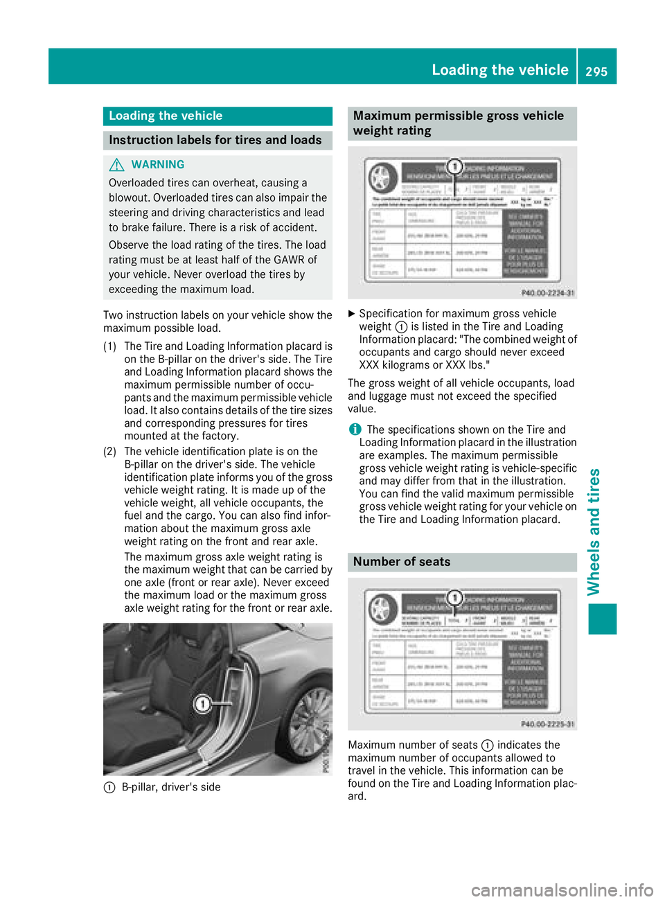
Two instruction labels on your vehicle show the maximum possible load.
(1) The Tire and Loading Information placard is on the B-pillar on the driver's side. The Tire
and Loading Information placard shows the
maximum permissible number of occu-
pants and the maximum permissible vehicle
load. It also contains details of the tire sizes
and corresponding pressures for tires
mounted at the factory.
(2) The vehicle identification plate is on the B-pillar on the driver's side. The vehicle
identification plate informs you of the gross
vehicle weight rating. It is made up of the
vehicle weight, all vehicle occupants, the
fuel and the cargo. You can also find infor-
mation about the maximum gross axle
weight rating on the front and rear axle.
The maximum gross axle weight rating is
the maximum weight that can be carried by
one axle (front or rear axle). Never exceed
the maximum load or the maximum gross
axle weight rating for the front or rear axle.
:B-pillar, driver's side
Maximum permissible gross vehicle
weight rating
XSpecification for maximum gross vehicle
weight :is listed in the Tire and Loading
Information placard: "The combined weight of occupants and cargo should never exceed
XXX kilograms or XXX lbs."
The gross weight of all vehicle occupants, load
and luggage must not exceed the specified
value.
iThe specifications shown on the Tire and
Loading Information placard in the illustration are examples. The maximum permissible
gross vehicle weight rating is vehicle-specific
and may differ from that in the illustration.
You can find the valid maximum permissible
gross vehicle weight rating for your vehicle on
the Tire and Loading Information placard.
Number of seats
Maximum number of seats :indicates the
maximum number of occupants allowed to
travel in the vehicle. This information can be
found on the Tire and Loading Information plac-
ard.
Loading the vehicle295
Wheels and tires
Z
Page 305 of 322
Curb weight
The weight of a vehicle with standard equipment
including the maximum capacity of fuel, oil and
coolant. It also includes the air-conditioning sys-
tem and optional equipment if these are instal-
led in the vehicle, but does not include passen-
gers or luggage.
Maximum load rating
The maximum load rating is the maximum per-
missible weight in kilograms or lbs for which a
tire is approved.
Maximum permissible tire pressure
Maximum permissible tire pressure for one tire.
Maximum load on one tire
Maximum load on one tire. This is calculated by
dividing the maximum axle load of one axle by
two.
PSI (pounds per square inch)
A standard unit of measure for tire pressure.
Aspect ratio
Relationship between tire height and tire width
in percent.
Tire pressure
This is pressure inside the tire applying an out-
ward force to each square inch of the tire's sur-
face. The tire pressure is specified in pounds per
square inch (psi), in kilopascal (kPa) or in bar.
The tire pressure should only be corrected when
the tires are cold.
Cold tire pressure
The tires are cold:
Rif the vehicle has been parked with the tires
out of direct sunlight for at least three hours
and
Rif the vehicle has not been driven further than
1 mile (1.6 km)
Tread
The part of the tire that comes into contact with
the road.
Bead
The tire bead ensures that the tire sits securely
on the wheel. There are several steel wires in the
bead to prevent the tire from coming loose from the wheel rim.
Sidewall
The part of the tire between the tread and the
bead.
Weight of optional extras
The combined weight of those optional extras
that weigh more than the replaced standard
parts and more than 2.3 kg (5 lbs).Thes e
option al extras, such as high-performance
brakes, level control, a roof rack or a high-per-
formance battery, are not included in the curb
weight and the weight of the accessories.
TIN (Tire Identification Number)
This is a unique identifier which can be used by
a tire manufacturer to identify tires, for example
for a product recall, and thus identify the pur-
chasers. The TIN is made up of the manufactur-
er's identity code, tire size, tire type code and
the manufacturing date.
Load bearing index
The load bearing index (also load index) is a code
that contains the maximum load bearing capa-
city of a tire.
Traction
Traction is the result of friction between the tires
and the road surface.
Treadwear indicators
Narrow bars (tread wear bars) that are distrib-
uted over the tire tread. If the tire tread is level
with the bars, the wear limit of áin (1.6 mm)
has been reached.
Occupant distribution
The distribution of occupants in a vehicle at their
designated seating positions.
Total load limit
Nominal load and luggage load plus 68 kg
(150 lbs) multiplied by the number of seats in
the vehicle.
Changing a wheel
Flat tire
The "Breakdown assistance" section
(Ypage 271) contains information and notes on
how to deal with a flat tire. Information on driv-
ing with MOExtended tires in the event of a flat
Changing a wheel303
Wheels and tires
Z
Page 306 of 322
tire can be found under "MOExtended tires (tires
with run-flat characteristics" (Ypage 271).
Rotating the wheels
GWARNING
Interchanging the front and rear wheels may
severely impair the driving characteristics if
the wheels or tires have different dimensions. The wheel brakes or suspension components
may also be damaged. There is a risk of acci-
dent.
Rotate front and rear wheels only if the wheels and tires are of the same dimensions.
!On vehicles equipped with a tire pressure
monitor, electronic components are located
in the wheel.
Tire-mounting tools should not be used near
the valve. This could damage the electronic
components.
Only have tires changed at a qualified spe-
cialist workshop.
Always pay attention to the instructions and
safety notes when changing a wheel
(
Ypage 304).
The wear patterns on the front and rear tires
differ, depending on the operating conditions.
Rotate the wheels before a clear wear pattern
has formed on the tires. Front tires typically
wear more on the shoulders and the rear tires in
the center.
On vehicles that have the same size front and
rear wheels, you can rotate the wheels accord-
ing to the intervals in the tire manufacturer's
warranty book in your vehicle documents. If no
warranty book is available, the tires s
hould be
rotated every 3,000 to 6,000 miles (5,000 to
10,000 km). Depending on tire wear, this may
be required earlier. Do not change the direction
of wheel rotation.
Clean the contact surfaces of the wheel and the
brake disc thoroughly every time a wheel is rota- ted. Check the tire pressure and reactivate the
tire pressure monitor if necessary.
Direction of rotation
Tires with a specified direction of rotation have
additional benefits, e.g. if there is a risk of hydro- planing. These advantages can only be gained if
the tires are installed corresponding to the
direction of rotation.
An arrow on the sidewall of the tire indicates its
correct direction of rotation.
Storing wheels
Store wheels that are not being used in a cool,
dry and preferably dark place. Protect the tires
from oil, grease, gasoline and diesel.
Mounting a wheel
Preparing the vehicle
XStop the vehicle on solid, non-slippery and
level ground.
XUnload the vehicle. The jack can only be used
when the vehicle is unladen.
XApply the electric parking brake manually.
XBring the front wheels into the straight-ahead
position.
XShift the transmission to position j.
XSwitch off the engine.
XVehicles without KEYLESS-GO:remove the
SmartKey from the ignition lock.
XVehicles with KEYLESS-GO: open the driv-
er's door.
The vehicle electronics now have status 0.
This is the same as the SmartKey having been
removed.
XVehicles with KEYLESS-GO: remove the
Start/Stop button from the ignition lock
(
Ypage 122).
XIf included in the vehicle equipment, remove
the tire-change tool kit from the vehicle.
XSafeguard the vehicle against rolling away.
304Changing a wheel
Wheels an d tires
Page 307 of 322
Securing the vehicle to prevent it from
rolling away
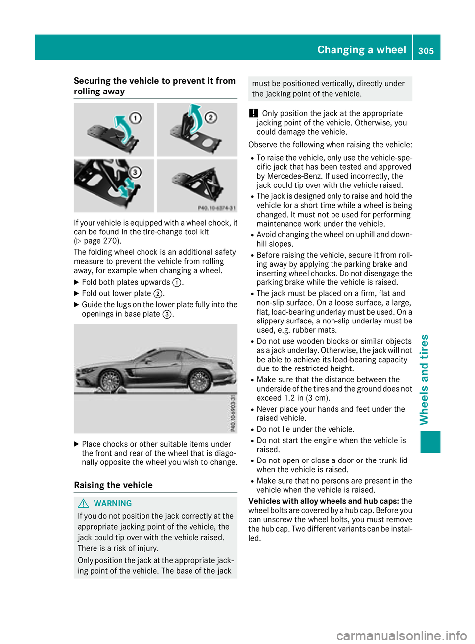
If your vehicle is equipped with a wheel chock, it
can be found in the tire-change tool kit
(
Ypage 270).
The folding wheel chock is an additional safety
measure to prevent the vehicle from rolling
away, for example when changing a wheel.
XFold both plates upwards :.
XFold out lower plate;.
XGuide the lugs on the lower plate fully into the
openings in base plate =.
XPlace chocks or other suitable items under
the front and rear of the wheel that is diago-
nally opposite the wheel you wish to change.
Raising the vehicle
GWARNING
If you do not position the jack correctly at the
appropriate jacking point of the vehicle, the
jack could tip over with the vehicle raised.
There is a risk of injury.
Only position the jack at the appropriate jack-
ing point of the vehicle. The base of the jack
must be positioned vertically, directly under
the jacking point of the vehicle.
!Only position the jack at the appropriate
jacking point of the vehicle. Otherwise, you
could damage the vehicle.
Observe the following when raising the vehicle:
RTo raise the vehicle, only use the vehicle-spe-
cific jack that has been tested and approved
by Mercedes-Benz. If used incorrectly, the
jack could tip over with the vehicle raised.
RThe jack is designed only to raise and hold the
vehicle for a short time while a wheel is being
changed. It must not be used for performing
maintenance work under the vehicle.
RAvoid changing the wheel on uphill and down-
hill slopes.
RBefore raising the vehicle, secure it from roll-
ing away by applying the parking brake and
inserting wheel chocks. Do not disengage the
parking brake while the vehicle is raised.
RThe jack must be placed on a firm, flat and
non-slip surface. On a loose surface, a large,
flat, load-bearing underlay must be used. On a
slippery surface, a non-slip underlay must be
used, e.g. rubber mats.
RDo not use wooden blocks or similar objects
as a jack underlay. Otherwise, the jack will not be able to achieve its load-bearing capacity
due to the restricted height.
RMake sure that the distance between the
underside of the tires and the ground does not
exceed 1.2 in (3 cm).
RNever place your hands and feet under the
raised vehicle.
RDo not lie under the vehicle.
RDo not start the engine when the vehicle is
raised.
RDo not open or close a door or the trunk lid
when the vehicle is raised.
RMake sure that no persons are present in the
vehicle when the vehicle is raised.
Vehicles with alloy wheels and hub caps: the
wheel bolts are covered by a hub cap. Before you
can unscrew the wheel bolts, you must remove
the hub cap. Two different variants can be instal- led.
Changing a wheel305
Wheels and tires
Z
Page 309 of 322
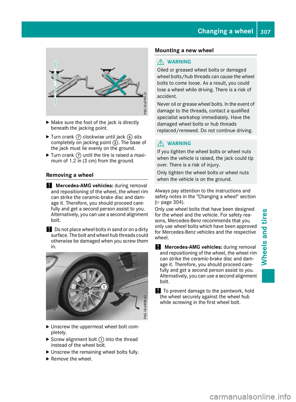
XMake sure the foot of the jack is directly
beneath the jacking point.
XTurn crankCclockwise until jack Bsits
completely on jacking point A. The base of
the jack must lie evenly on the ground.
XTurn crank Cuntil the tire is raised a maxi-
mum of 1.2 in (3 cm) from the ground.
Removing a wheel
!Mercedes-AMG vehicles: during removal
and repositioning of the wheel, the wheel rim
can strike the ceramic-brake disc and dam-
age it. Therefore, you should proceed care-
fully and get a second person assist to you.
Alternatively, you can use a second alignment
bolt.
!Do not place wheel bolts in sand or on a dirty
surface. The bolt and wheel hub threads could
otherwise be damaged when you screw them
in.
XUnscrew the uppermost wheel bolt com-
pletely.
XScrew alignment bolt :into the thread
instead of the wheel bolt.
XUnscrew the remaining wheel bolts fully.
XRemove the wheel.
Mounting a new wheel
GWARNING
Oiled or greased wheel bolts or damaged
wheel bolts/hub threads can cause the wheel bolts to come loose. As a result, you could
lose a wheel while driving. There is a risk of
accident.
Never oil or grease wheel bolts. In the event of
damage to the threads, contact a qualified
specialist workshop immediately. Have the
damaged wheel bolts or hub threads
replaced/renewed. Do not continue driving.
GWARNING
If you tighten the wheel bolts or wheel nuts
when the vehicle is raised, the jack could tip
over. There is a risk of injury.
Only tighten the wheel bolts or wheel nuts
when the vehicle is on the ground.
Always pay attention to the instructions and
safety notes in the "Changing a wheel" section
(
Ypage 304).
Only use wheel bolts that have been designed
for the wheel and the vehicle. For safety rea-
sons, Mercedes-Benz recommends that you
only use wheel bolts which have been approved for Mercedes-Benz vehicles and the respective
wheel.
!Mercedes-AMG vehicles: during removal
and repositioning of the wheel, the wheel rim
can strike the ceramic-brake disc and dam-
age it. Therefore, you should proceed care-
fully and get a second person assist to you.
Alternatively, you can use a second alignment
bolt.
!To prevent damage to the paintwork, hold
the wheel securely against the wheel hub
while screwing in the first wheel bolt.
Changing a wheel307
Wheels and tires
Z
Page 314 of 322
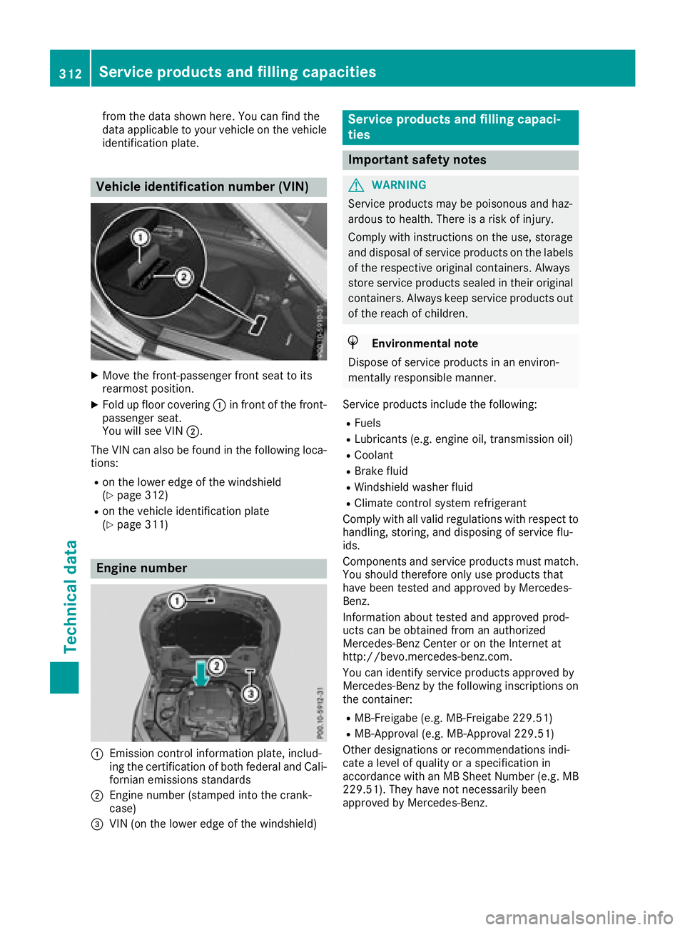
from the data shown here. You can find the
data applicable to your vehicle on the vehicle
identification plate.
Vehicle identification number (VIN)
XMove the front-passenger front seat to its
rearmost position.
XFold up floor covering:in front of the front-
passenger seat.
You will see VIN ;.
The VIN can also be found in the following loca-
tions:
Ron the lower edge of the windshield
(Ypage 312)
Ron the vehicle identification plate
(Ypage 311)
Engine number
:Emission control information plate, includ-
ing the certification of both federal and Cali-
fornian emissions standards
;Engine number (stamped into the crank-
case)
=VIN (on the lower edge of the windshield)
Service products and filling capaci-
ties
Important safety notes
GWARNING
Service products may be poisonous and haz-
ardous to health. There is a risk of injury.
Comply with instructions on the use, storage
and disposal of service products on the labels
of the respective original containers. Always
store service products sealed in their original
containers. Always keep service products out
of the reach of children.
HEnvironmental note
Dispose of service products in an environ-
mentally responsible manner.
Service products include the following:
RFuels
RLubricants (e.g. engine oil, transmission oil)
RCoolant
RBrake fluid
RWindshield washer fluid
RClimate control system refrigerant
Comply with all valid regulations with respect to
handling, storing, and disposing of service flu-
ids.
Components and service products must match.
You should therefore only use products that
have been tested and approved by Mercedes-
Benz.
Information about tested and approved prod-
ucts can be obtained from an authorized
Mercedes-Benz Center or on the Internet at
http://bevo.mercedes-benz.com.
You can identify service products approved by
Mercedes-Benz by the following inscriptions on
the container:
RMB-Freigabe (e.g. MB-Freigabe 229.51)
RMB-Approval (e.g. MB-Approval 229.51)
Other designations or recommendations indi-
cate a level of quality or a specification in
accordance with an MB Sheet Number (e.g. MB
229.51). They have not necessarily been
approved by Mercedes-Benz.
312Service products and filling capacities
Technical data
Page 317 of 322

iMB approval is indicated on the oil contain-
ers.
Filling capacities
The following values refer to an oil change
including the oil filter.
Missing values were not available at time of
going to print.
ModelCapacity
SL 4506.9 US qt (6.5 l)
SL 5508.5 US qt (8.0l)
Mercedes‑AMG
SL 638.9 US qt (8.5l)
Mercedes‑AMG
SL 6510.5 US qt (10.0 l)
Additives
!Do not use any additives in the engine oil.
This could damage the engine.
Brake fluid
GWARNING
The brake fluid constantly absorbs moisture
from the air. This lowers the boiling point of
the brake fluid. If the boiling point of the brake
fluid is too low, vapor pockets may form in the
brake system when the brakes are applied
hard. This would impair braking efficiency.
There is a risk of an accident.
You should have the brake fluid renewed at
the specified intervals.
When handling brake fluid, observe the impor-
tant safety notes on service products
(
Ypage 312).
The brake fluid change intervals can be found in
the Maintenance Booklet.
Only use brake fluid approved by Mercedes-
Benz in accordance with MB-Freigabe or MB-
Approval 331.0.
Information about approved brake fluid can be
obtained at any qualified specialist workshop or
on the Internet at
http://bevo.mercedes-benz.co m.
iHave the brake fluid regularly replaced at a
qualified specialist workshop and the replace-
ment confirmed in the Maintenance Booklet.
Coolant
Important safety notes
GWARNING
If antifreeze comes into contact with hot com- ponents in the engine compartment, it may
ignite. There is a risk of fire and injury.
Let the engine cool down before you add anti-
freeze. Make sure that antifreeze is not spilled
next to the filler neck. Thoroughly clean the
antifreeze from components before starting
the engine.
!Only add coolant that has been premixed
with the desired antifreeze protection. You
could otherwise damage the engine.
Further information on coolants can be found
in the Mercedes-Benz Specifications for Ser-
vice Products, MB BeVo 310.1, e.g. on the
Internet at
http://bevo.mercedes-benz.com. Or con-
tact a qualified specialist workshop.
!Always use a suitable coolant mixture, even
in countries where high temperatures prevail.
Otherwise, the engine cooling system is not
sufficiently protected from corrosion and
overheating.
iHave the coolant regularly replaced at a
qualified specialist workshop and the replace-
ment confirmed in the Maintenance Booklet.
Comply with the important safety precautions
for service products when handling coolant
(
Ypage 312).
The coolant is a mixture of water and anti-
freeze/corrosion inhibitor. It is responsible for
the following:
Ranti-corrosion protection
Rantifreeze protection
Rraising the boiling point
If the coolant has antifreeze protection down to
-35 ‡ (-37 †), the boiling point of the coolant
during operation is approximately 266 ‡
(130 †).
Service products and filling capacities315
Technical data
Z