Page 407 of 562
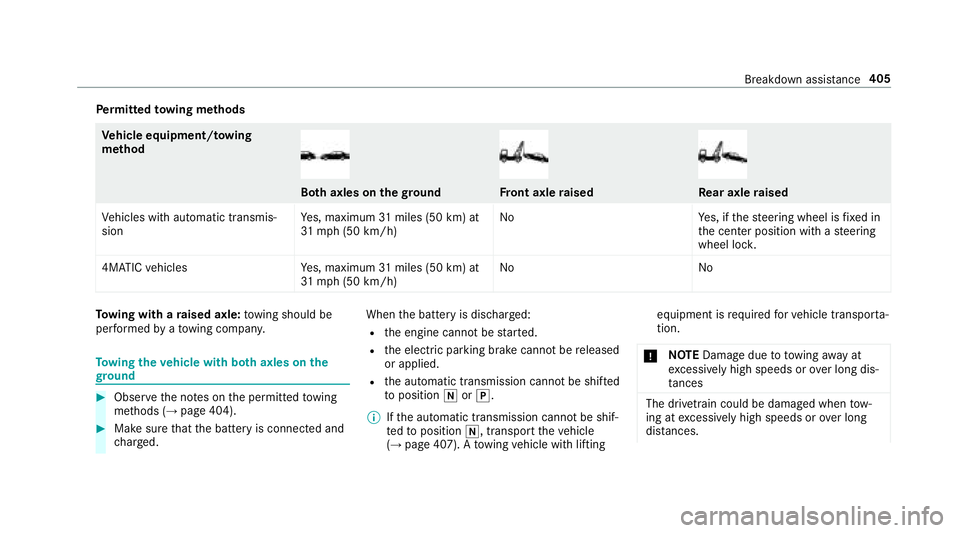
Perm itted towing me thods
Ve hicle equipment/to wing
me thod
Bo th axles on thegr oundFront axle raisedRe ar axle raised
Ve hicles with automatic transmis‐
sion Ye
s, maximum 31miles (50 km) at
31 mp h (50 km/h) No
Yes, if thesteering wheel is fixe d in
th e center position with a steering
wheel loc k.
4MATIC vehicles Yes, maximum 31miles (50 km) at
31 mp h (50 km/h) No
No
Towing wit h araised axle: towing should be
per form ed byato wing compan y.
Towing theve hicle with bo thaxles on the
gr ound
#Obser vethe no tes on the permitted towing
me thods (→page 404).
#Make sure that the battery is connected and
ch arge d. When
the battery is dischar ged:
Rthe engine cannot bestar ted.
Rth e electric parking brake cannot bereleased
or applied.
Rth e automatic transmission cann otbe shif ted
to position iorj.
% Ifth e automatic transmission cannot be shif‐
te dto position i, transport theve hicle
(
→page 407). A towing vehicle with lifting equipment is
requiredforve hicle transpor ta‐
tion.
* NO
TEDama gedue to to wing away at
exc essively high speeds or over long dis‐
ta nces
The driv etra in could be damaged when tow‐
ing at excessively high speeds or over long
dis tances.
Breakdown assist ance405
Page 410 of 562
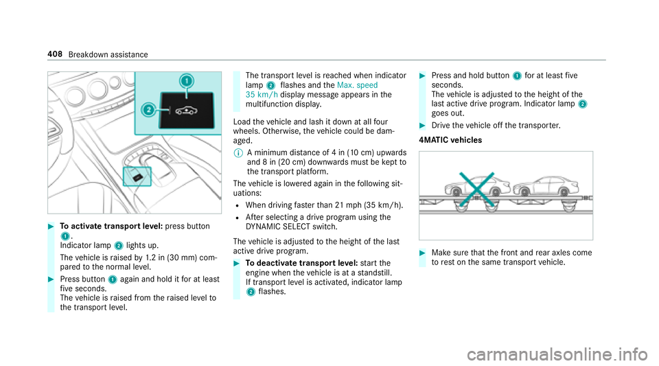
#Toactivate transport leve l:press button
1.
Indicator lamp 2lights up.
The vehicle is raised by1.2 in (30 mm) com‐
pared tothe normal le vel.
#Press button 1again and hold it for at least
fi ve seconds.
The vehicle is raised from thera ised le velto
th e transport le vel.
The transport le vel is reached when indicator
lamp 2flashes and the�0�D�[�� �V�S�H�H�G
���� �N�P���K display message appears in the
multifunction displa y.
Load theve hicle and lash it down at all four
wheels. Otherwise, theve hicle could be dam‐
aged.
% A minimum dis tance of 4 in (10 cm) up wards
and 8 in (20 cm) down wards must be kept to
th e transport platform.
The vehicle is lo wered again in thefo llowing sit‐
uations:
RWhen driving fasterthan 21 mp h (35 km/h).
RAfter selecting a drive program using the
DY NA MIC SELECT switch.
The vehicle is adjus tedto the height of the last
active drive prog ram.
#To deactivate transpo rtleve l:start the
engine when theve hicle is at a standstill.
If transport leve l is activated, indicator lamp
2 flashes.
#Press and hold button 1for at least five
seconds.
The vehicle is adjus tedto the height of the
last active drive prog ram. Indicator lamp 2
goes out.
#Drive theve hicle off the transpor ter.
4MATIC vehicles
#Make sure that the front and rear axles come
to rest on the same transport vehicle.
408
Breakdown assis tance
Page 411 of 562
*NO
TEDama getothe driv etra in due to
incor rect positioning
#Do not position theve hicle abo vethe
connection point of the transport vehi‐
cle.
To wing eye
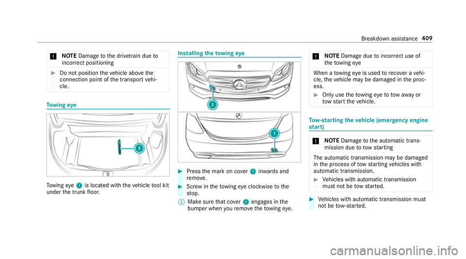
Towing eye1 is located with theve hicle tool kit
under the trunk floor.
Installing theto wing eye
#Press the mark on co ver1 inwa rds and
re mo ve.
#Scr ew intheto wing eyeclockwise tothe
st op.
% Make sure that co ver1 engages in the
bumper when youre mo vetheto wing eye. *
NO
TEDama gedue toincor rect use of
th eto wing eye
When a towing eye is used toreco ver a vehi‐
cle, theve hicle may be damaged in the proc‐
ess.
#Only use theto wing eyeto to waw ay or
to w start theve hicle.
To w- starting theve hicle (eme rgency engine
st art)
* NO
TEDama getothe automatic trans‐
mission due to towstarting
The automatic transmission may be damaged
in the process of tow starting vehicles with
automatic transmission.
#Ve hicles with automatic transmission
must not be tow star ted.
#Ve hicles with automatic transmission must
not be tow- star ted.
Breakdown assis tance 409
Page 412 of 562

Electrical fuses
Notes on electrical fuses
&
WARNING Risk of accident and injury
due to ov erloaded lines
If yo u man ipulate orbridg e afaulty fuse or if
yo ure place it with a fuse with a higher
amperage, the electric line could be overloa‐
ded.
This could result in a fire .
#Alw aysre place faulty fuses with speci‐
fi ed new fuses conta iningthe cor rect
amperage.
* NO
TEDama gecaused byincor rect fuses
Incor rect fuses may cause damage toelectri‐
cal components or sy stems.
#Only use Mercedes-Benz appr oved
fuses with the cor rect fuse rating.
Blown fuses must bereplaced with fuses of the
same rating, which you can recognize bythe
color and fuse rating. The fuse ratings are li sted in
the fuse assignment diagram. The fuse assign‐
ment diagram is in theve hicle document wallet.
* NO
TEDama geor malfunctions caused
by moisture
Moisture may cause dama getothe electrical
sy stem or cause it tomalfunction.
#When the fuse box is open, make sure
th at no moisture can enter the fuse
box.
#When closing the fuse box, make sure
th at the seal of the lid is positioned cor‐
re ctly on the fuse box.
Ifth e newly inser ted fuse also blo ws, ha vethe
cause traced and rectified at a qualified special‐
ist workshop, e.g. an authorized Mercedes-Benz
Center.
Ensure thefo llowing before replacing a fuse:
RThe vehicle is secured against rolling away.
RAll electrical consumers are switched off.
RThe ignition is switched off. The electrical fuses are located in
various fuse
bo xes:
RFu se box in the engine compartment on the
driver's side (→page 410)
RFu se box on the driver's side of the dash‐
board (→page 412)
RFu se box in the front-passen gerfo ot we ll
(→page 412)
RFu se box in the trunk on theright-hand side
of theve hicle, when vie wed in the direction
of tra vel (
→page 412)
Fu se box in the engine compa rtment
Requ irements:RObser vethe no tes on electrical fuses
(→page 410).
Ha ve thefo llowing readily available:
RA dry clo th
RA screwdriver
410
Breakdown assis tance
Page 413 of 562
Opening
&WARNING Risk of injury from usingthe
windshield wipers while the engine hood
is open
When the engine hood is open and the wind‐
shield wipers are set in motion, you can be
trapped bythe wiper linkage.
#Alw ays switch off the windshield wipers
and ignition before opening the engine
hood.
#Re lease retaining clips 1.
Pull co ver2 up.#Remo veany existing moisture from the fuse
box using a dry clo th.
#Loosen scr ews4, remo vefuse box lid 3
from theto p.
Closing
#Check whe ther the seal is positioned cor‐
re ctly in the lid.
Breakdown assis tance 41
1
Page 439 of 562
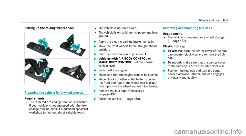
Setting upthefo lding wheel chock
Prepa ring theve hicle for a wheel change
Re quirements:RThe requ ired tire-change tool kit is available.
If yo ur vehicle is not equipped with the tire-
ch ange tool kit, consult a qualified specialist
wo rkshop tofind out about suitable tools.
RThe vehicle is not on a slope.
RThe vehicle is on solid, non-slippery and le vel
ground .
#Applythe electric parking brake manually.
#Mo vethe front wheels tothest ra ight-ahead
position.
#Shift the transmission toposition j.
#Vehicles with AIR BODY CONT ROL or
MAGIC BODY CONT ROL:Set the normal
ve hicle le vel.
#Swit choff the engine.
#Make sure that the engine cannot bestar ted.
#Place choc ks orother suitable items under
th e front and rear of the wheel that is diago‐
nally opposite the wheel youwish tochange.
#Re mo vethe hub caps if necessary
(→page 437).
#Ra ise theve hicle (→page 438).
Re moving and mounting hub caps
Requirement:RThe vehicle is prepared for a wheel change
(→page 437).
Plast ic hub cap
#Toremo ve:turn the center co ver of the hub
cap counter-clockwise and remo vethe hub
cap.
#To mount: makesurethat the center co ver
of the hub cap is turned counter-clockwise.
#Po sition the hub cap and turn the center
co ver clockwise until the hub cap engages
ph ysically and audibly.
Wheels and tires 437
Page 440 of 562
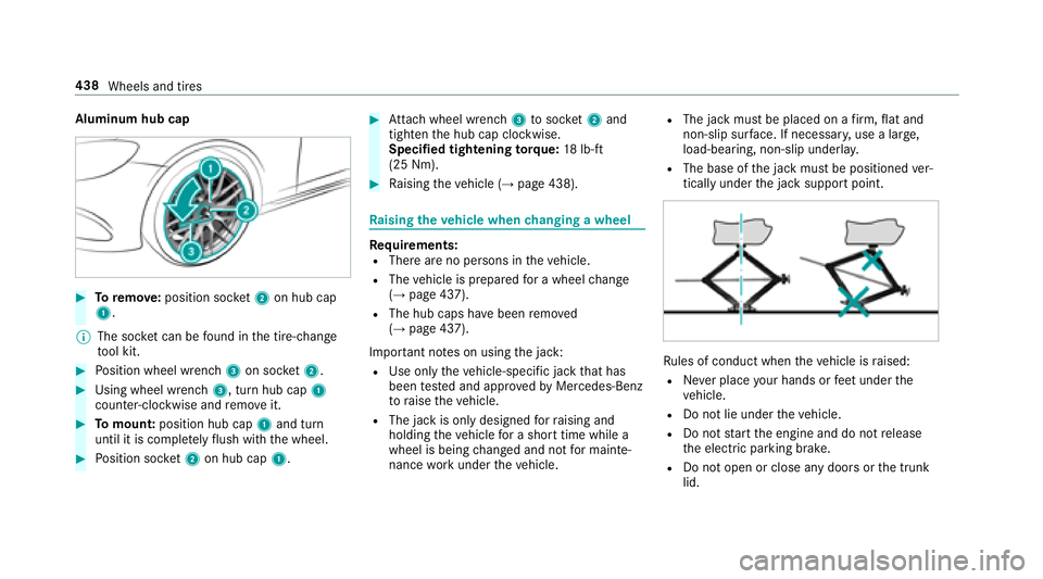
Aluminum hub cap
#Toremo ve:position soc ket2 on hub cap
1.
% The soc ket can be found inthe tire-change
to ol kit.
#Po sition wheel wrench 3on soc ket2.
#Using wheel wrench 3, turn hub cap1
counter-clo ckwise and remo veit.
#To mount: position hub cap 1and turn
until it is compl etely flush withth e wheel.
#Po sition soc ket2 on hub cap 1.
#Attach wheel wrench 3tosoc ket2 and
tighten the hub cap clockwise.
Specified tightening torq ue: 18lb-ft
(25 Nm).
#Ra ising theve hicle (→page 438).
Ra ising theve hicle when changing a wheel
Re quirements:RThere are no persons in theve hicle.
RThe vehicle is prepared for a wheel change
(→page 437).
RThe hub caps ha vebeen remo ved
(→page 437).
Impor tant no tes on using the jack:
RUse only theve hicle-specific jack that has
been tested and appr oved byMercedes-Benz
to raise theve hicle.
RThe jack is only designed forra ising and
holding theve hicle for a short time while a
wheel is being changed and not for mainte‐
nance workunder theve hicle.
RThe jack must be placed on a firm ,fl at and
non-slip sur face. If necessar y,use a lar ge,
load-bearing, non-slip underla y.
RThe base ofthe jack must be positioned ver‐
tically under the jack support point.
Ru les of conduct when theve hicle is raised:
RNe ver place your hands or feet under the
ve hicle.
RDo not lie under theve hicle.
RDo not start the engine and do not release
th e electric parking brake.
RDo not open or close any doors or the trunk
lid.
438 Wheels and tires
Page 447 of 562
Thefollowing can be used in theve hicle without
re strictions:
RRF transmitters wi tha maximum transmis‐
sion output of up to100 mW
RRF transmitters with transmitter frequencies
inthe 380 - 410 MHz frequency band and a
maximum transmission output of up to2 W
(trunked radio sy stem/T etra )
RMobile phones (2G/3G/4G)
There are no restrictions when positioning the
antenna on the outside of theve hicle for some
frequency bands.
This applies tothefo llowing frequency bands:
RTrunked radio sy stem/T etra
R70 cm waveband
R2G/3G/4G
Ve hicle identification plate, VIN and engine
number overview
Ve hicle identification plate
Vehicle identification plate (USA only)
1Perm issible grossmass
2Pe rm issible front axle load
3Perm issible rear axle load
4Pa int code
5VIN (vehicle identification number)
Tech nical da ta44
5