2018 MERCEDES-BENZ GLS tow
[x] Cancel search: towPage 353 of 398
the combination switch, the hazard warning
lamp starts flashing again.
Transporting the vehicle
4MATIC vehicles/vehicles with auto-
matic transmission
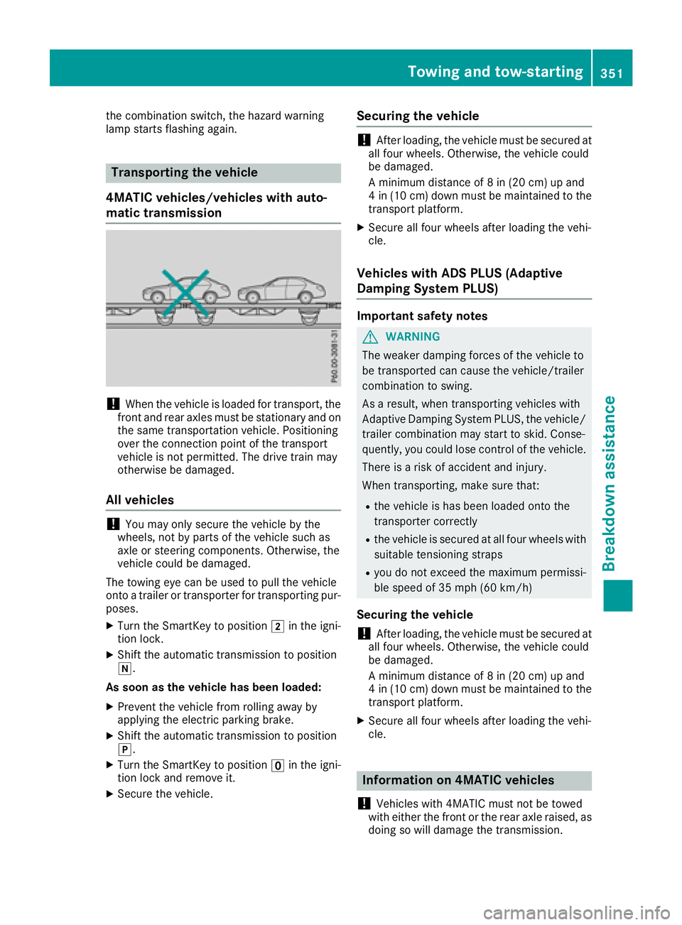
! When the vehicle is loaded for transport, the
front and rear axles must be stationary and on
the same transportation vehicle. Positioning
over the connection point of the transport
vehicle is not permitted. The drive train may
otherwise be damaged.
All vehicles
! You may only secure the vehicle by the
wheels, not by parts of the vehicle such as
axle or steering components. Otherwise, the
vehicle could be damaged.
The towing eye can be used to pull the vehicle
onto a trailer or transporter for transporting pur-
poses. X
Turn the SmartKey to position �H in the igni-
tion lock. X
Shift the automatic transmission to position
�\\ .
As soon as the vehicle has been loaded: X
Prevent the vehicle from rolling away by
applying the electric parking brake. X
Shift the automatic transmission to position
�] . X
Turn the SmartKey to position �
Page 354 of 398
Vehicles with 4MATIC may either be towed away
with both axles on the ground or be loaded up
and transported.
If the vehicle's transmission, front, or rear axle is
damaged, have the vehicle transported on a
truck or trailer.
In the event of damage to the electrical sys-
tem: if the battery is defective, the automatic
transmission will be locked in position P . To shift
the automatic transmission to position N , you
must provide power to the vehicle's electrical
system in the same way as when jump-starting
( Y
page 346).
Have the vehicle transported on a transporter or
trailer.
Tow-starting (emergency engine
starting)
! Vehicles with automatic transmission must
not be tow-started. You could otherwise dam-
age the automatic transmission.
You can find information on "Jump-starting"
under ( Y
page 346).
Fuses
Important safety notes
G WARNING
If you manipulate or bridge a faulty fuse or if
you replace it with a fuse with a higher amper-
age, the electric cables could be overloaded.
This could result in a fire. There is a risk of an
accident and injury.
Always replace faulty fuses with the specified
new fuses having the correct amperage.
! For the fuse boxes in the engine compart-
ment and under the rear bench seat, only use
fuses with the suffix "S". Otherwise, compo-
nents or systems could be damaged.
! Make sure that no moisture can enter the
fuse box when the cover is open.
! When closing the cover, make sure that it is
lying correctly on the fuse box. Moisture seep-
ing in or dirt could otherwise impair the oper-
ation of the fuses. The fuses in your vehicle serve to close down
faulty circuits. If a fuse blows, all the compo-
nents on the circuit and their functions stop
operating.
Blown fuses must be replaced with fuses of the
same rating, which you can recognize by the
color and value. The fuse ratings are listed in the
fuse allocation chart.
The fuse allocation chart is located in the fuse
box under the rear bench seat ( Y
page 353).
If a newly inserted fuse also blows, have the
cause traced and rectified at a qualified special-
ist workshop, e.g. an authorized Mercedes-Benz
Center.
Before changing a fuse Observe the important safety notes
( Y
page 352) X
Switch off the engine. X
Switch off all electrical consumers. X
Remove the SmartKey from the ignition lock.
Or, on vehicles with KEYLESS-GO start function
or KEYLESS ‑ GO: X
Open the driver's door.
The vehicle electronics are now in key posi-
tion �
Page 368 of 398
able cargo and luggage load capacity is
650 lbs (1400 - 750 (5 x 150) = 650 lbs). X
Step 5: Determine the combined weight of
luggage and cargo being loaded on the vehi- cle. That weight may not safely exceed the
available cargo and luggage load capacity cal-
culated in step 4.
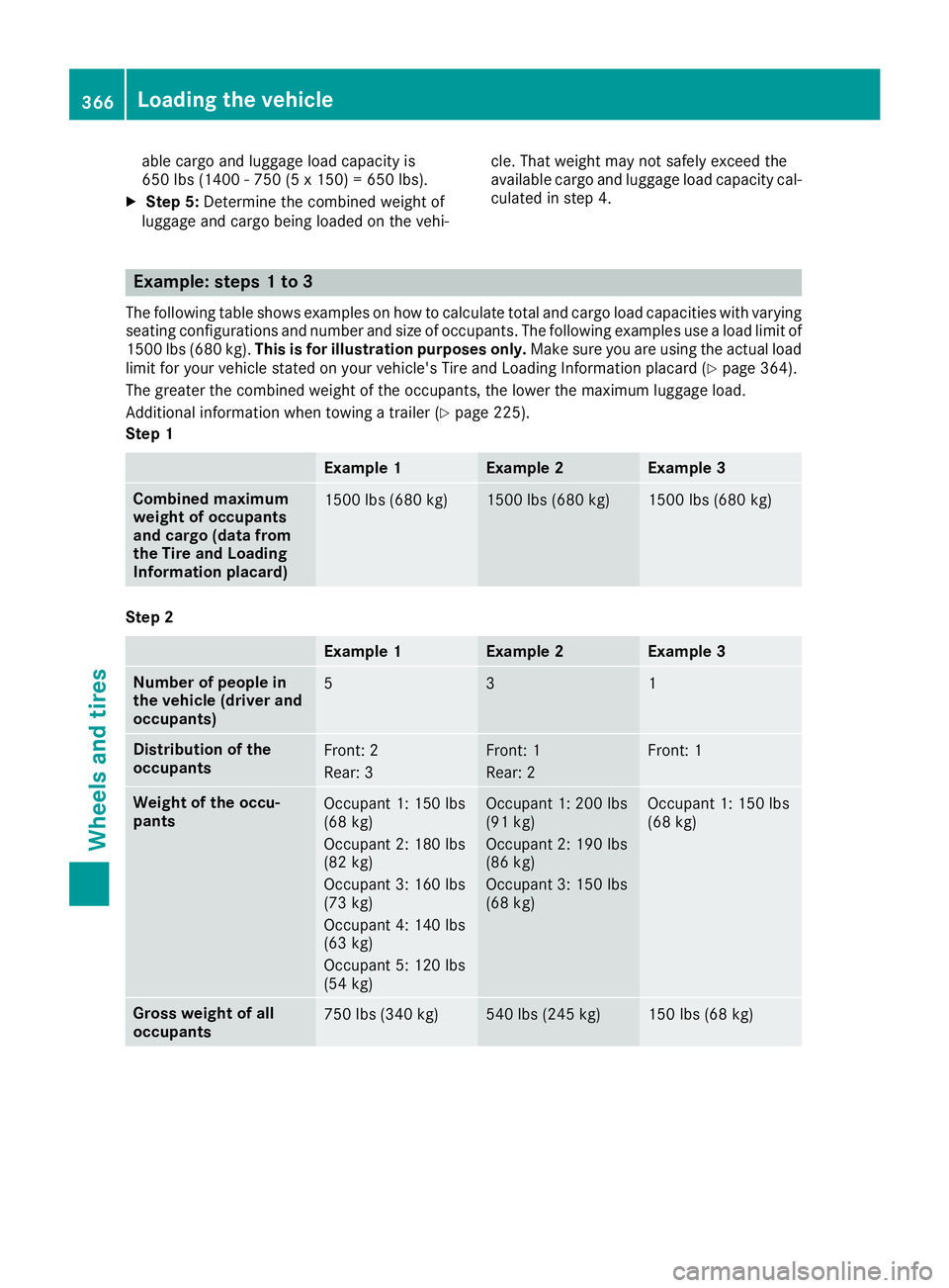
Example: steps 1 to 3 The following table shows examples on how to calculate total and cargo load capacities with varying
seating configurations and number and size of occupants. The following examples use a load limit of
1500 lbs (680 kg). This is for illustration purposes only. Make sure you are using the actual load
limit for your vehicle stated on your vehicle's Tire and Loading Information placard ( Y
page 364).
The greater the combined weight of the occupants, the lower the maximum luggage load.
Additional information when towing a trailer ( Y
page 225).
Step 1
Example 1 Example 2 Example 3
Combined maximum
weight of occupants
and cargo (data from
the Tire and Loading
Information placard) 1500 lbs (680 kg) 1500 lbs (680 kg) 1500 lbs (680 kg)
Step 2
Example 1 Example 2 Example 3
Number of people in
the vehicle (driver and
occupants) 5 3 1
Distribution of the
occupants Front: 2
Rear: 3 Front: 1
Rear: 2 Front: 1
Weight of the occu-
pants Occupant 1: 150 lbs
(68 kg)
Occupant 2: 180 lbs
(82 kg)
Occupant 3: 160 lbs
(73 kg)
Occupant 4: 140 lbs
(63 kg)
Occupant 5: 120 lbs
(54 kg) Occupant 1: 200 lbs
(91 kg)
Occupant 2: 190 lbs
(86 kg)
Occupant 3: 150 lbs
(68 kg) Occupant 1: 150 lbs
(68 kg)
Gross weight of all
occupants 750 lbs (340 kg) 540 lbs (245 kg) 150 lbs (68 kg)366
Loading the vehicle
Wheels and tires
Page 376 of 398
Sidewall The part of the tire between the tread and the
bead.
Weight of optional extras The combined weight of those optional extras
that weigh more than the replaced standard
parts and more than 2.3 kg (5 lbs). These
optional extras, such as high-performance
brakes, level control, a roof rack or a high-per-
formance battery, are not included in the curb
weight and the weight of the accessories.
TIN (Tire Identification Number) This is a unique identifier which can be used by
a tire manufacturer to identify tires, for example
for a product recall, and thus identify the pur-
chasers. The TIN is made up of the manufactur-
er's identity code, tire size, tire type code and
the manufacturing date.
Load bearing index The load bearing index (also load index) is a code
that contains the maximum load bearing capa-
city of a tire.
Traction Traction is the result of friction between the tires
and the road surface.
TWR (Tongue Weight Rating) The TWR specifies the maximum permissible
weight that the ball coupling of the trailer tow
hitch can support.
Treadwear indicators Narrow bars (tread wear bars) that are distrib-
uted over the tire tread. If the tire tread is level
with the bars, the wear limit of �
Page 383 of 398
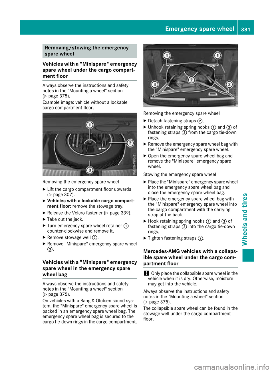
Removing/stowing the emergency
spare wheel
Vehicles with a "Minispare" emergency
spare wheel under the cargo compart-
ment floor Always observe the instructions and safety
notes in the "Mounting a wheel" section
( Y
page 375).
Example image: vehicle without a lockable
cargo compartment floor.
Removing the emergency spare wheel X
Lift the cargo compartment floor upwards
( Y
page 307). X
Vehicles with a lockable cargo compart-
ment floor: remove the stowage tray.X
Release the Velcro fastener ( Y
page 339).X
Take out the jack. X
Turn emergency spare wheel retainer �C
counter-clockwise and remove it. X
Remove stowage well �D .X
Remove "Minispare" emergency spare wheel
�
Page 384 of 398
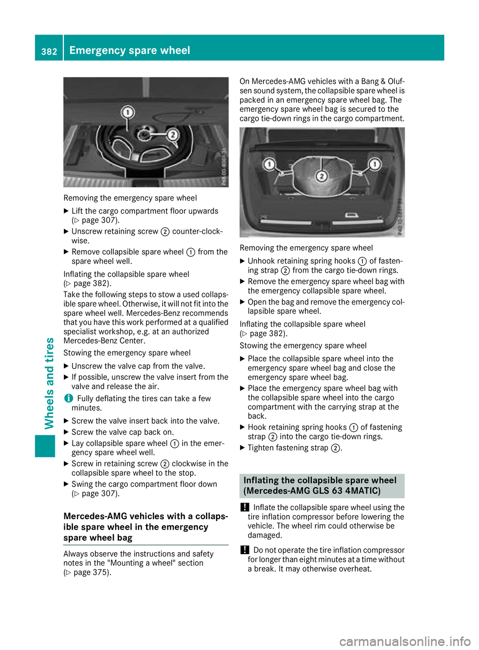
Removin g th e emergenc y spar e whee lX
Lif t th e cargo compartmen t floor upwards
( Y
page 307).X
Unscrew retaining screw �D counter-clock -
wise. X
Remove collapsible spar e whee l �C from th e
spar e whee l well.
Inflating th e collapsible spar e whee l
( Y
page 382).
Tak e th e followin g steps to stow a used collaps -
ible spar e wheel. Otherwise, it will no t fit int o th e
spar e whee l well. Mercedes-Ben z recommends
that you hav e this wor k performed at a qualified
specialist workshop, e.g. at an authorize d
Mercedes-Ben z Center.
Stowin g th e emergenc y spar e whee lX
Unscrew th e valv e cap from th e valve.X
If possible, unscrew th e valv e insert from th e
valv e and release th e air.
i Full y deflating th e tires can tak e a few
minutes. X
Screw th e valv e insert bac k int o th e valve.X
Screw th e valv e cap bac k on .X
Lay collapsible spar e whee l �C in th e emer-
gency spar e whee l well.X
Screw in retaining screw �D clockwise in th e
collapsible spar e whee l to th e stop.X
Swing th e cargo compartmen t floor down
( Y
page 307).
Mercedes-AMG vehicles with a collaps-
ible spare wheel in the emergency
spare wheel bag
Always observ e th e instruction s and safet y
note s in th e "Mounting a wheel" section
( Y
page 375). On Mercedes-AM G vehicles wit h a Ban g & Oluf -
sen soun d system, th e collapsible spar e whee l is
packe d in an emergenc y spar e whee l bag. The
emergenc y spar e whee l bag is secured to th e
cargo tie-down rings in th e cargo compartment.
Removin g th e emergenc y spar e whee lX
Unhoo k retaining spring hooks �C of fasten-
ing strap �D from th e cargo tie-down rings.X
Remove th e emergenc y spar e whee l bag wit h
th e emergenc y collapsible spar e wheel.X
Open th e bag and remove th e emergenc y col-
lapsible spar e wheel.
Inflating th e collapsible spar e whee l
( Y
page 382).
Stowin g th e emergenc y spar e whee lX
Plac e th e collapsible spar e whee l int o th e
emergenc y spar e whee l bag and close th e
emergenc y spar e whee l bag.X
Plac e th e emergenc y spar e whee l bag wit h
th e collapsible spar e whee l int o th e cargo
compartmen t wit h th e carryin g strap at th e
back. X
Hook retaining spring hooks �C of fastenin g
strap �D int o th e cargo tie-down rings.X
Tighte n fastenin g strap �D .
Inflating the collapsible spare wheel
(Mercedes-AMG GLS 63 4MATIC)
! Inflat e th e collapsible spar e whee l usin g th e
tire inflation compressor before lowering th e
vehicle. The whee l rim could otherwise be
damaged.
! Do no t operate th e tire inflation compressor
for longer than eigh t minute s at a time without
a break. It may otherwise overheat.382
Emergency spare wheel
Wheels and tires
Page 385 of 398
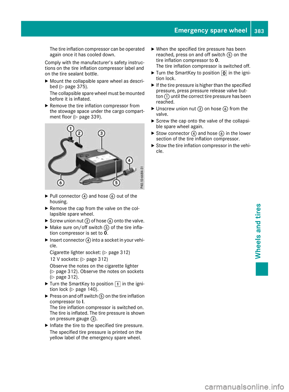
The tire inflation compressor can be operated
again once it has cooled down.
Comply with the manufacturer's safety instruc-
tions on the tire inflation compressor label and
on the tire sealant bottle. X
Mount the collapsible spare wheel as descri-
bed ( Y
page 375).
The collapsible spare wheel must be mounted
before it is inflated. X
Remove the tire inflation compressor from
the stowage space under the cargo compart-
ment floor ( Y
page 339).
X
Pull connector �
Page 397 of 398
Accelerate carefully and make sure that the
wheels do not spin when driving on steep ter-
rain.
i If the load on the front axle is reduced when
pulling away on a steep uphill slope, the front
wheels have a tendency to spin. 4ETS recog-
nizes this and brakes the wheels accordingly.
The rear wheel torque is increased, making it
easier to drive off.
For further information about the maximum gra-
dient climbing ability, see ( Y
page 173).
Trailer tow hitch
Mounting dimensions
! If you have a trailer tow hitch retrofitted,
changes to the cooling system and drive train
may be necessary, depending on the vehicle
type.
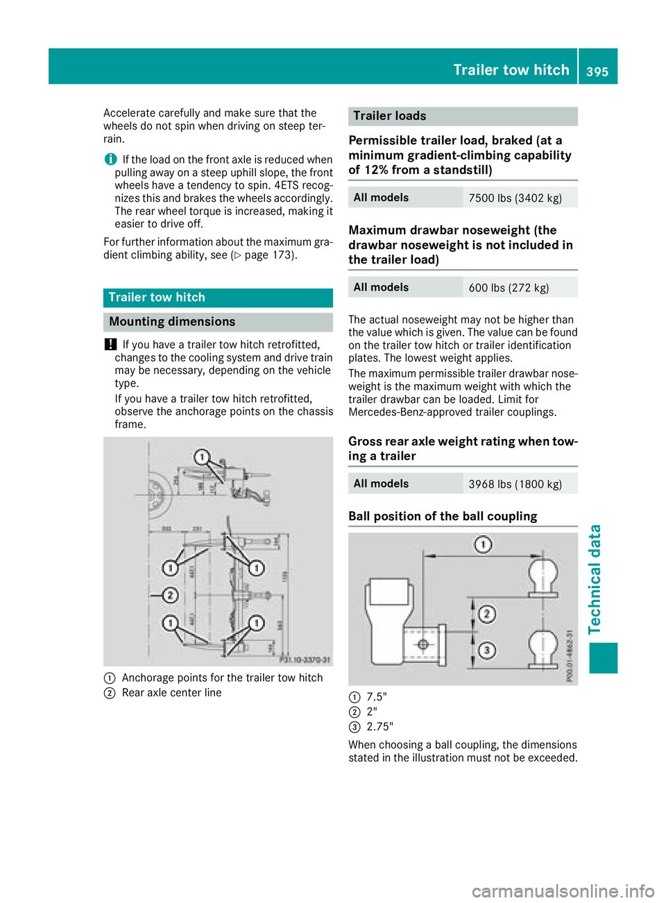
If you have a trailer tow hitch retrofitted,
observe the anchorage points on the chassis
frame.
�C
Anchorage points for the trailer tow hitch
�D
Rear axle center line Trailer loads
Permissible trailer load, braked (at a
minimum gradient-climbing capability
of 12% from a standstill) All models
7500 lbs (3402 kg)
Maximum drawbar noseweight (the
drawbar noseweight is not included in
the trailer load) All models
600 lbs (272 kg)
The actual noseweight may not be higher than
the value which is given. The value can be found
on the trailer tow hitch or trailer identification
plates. The lowest weight applies.
The maximum permissible trailer drawbar nose-
weight is the maximum weight with which the
trailer drawbar can be loaded. Limit for
Mercedes-Benz-approved trailer couplings.
Gross rear axle weight rating when tow-
ing a trailer All models
3968 lbs (1800 kg)
Ball position of the ball coupling
�C
7.5"
�D
2"
�