2018 MERCEDES-BENZ GLS tow bar
[x] Cancel search: tow barPage 24 of 398
Average weight of the vehicle
occupants (definition) .................... 372
Bar (definition) ............................... 372
Changing a wheel .......................... 374
Characteristics .............................. 372
Checking ........................................ 354
Curb weight (definition) ................. 373
Definition of terms ......................... 372
Direction of rotation ...................... 375
Display message ............................ 273
Distribution of the vehicle occu-
pants (definition) ............................ 374
DOT (Department of Transporta-
tion) (definition) ............................. 372
DOT, Tire Identification Number
(TIN) ............................................... 371
GAWR (Gross Axle Weight Rating)
(definition) ..................................... 372
GTW (Gross Trailer Weight) (defi-
nition) ............................................ 373
GVW (Gross Vehicle Weight) (def-
inition) ........................................... 373
GVWR (Gross Vehicle Weight Rat-
ing) (definition) .............................. 373
Important safety notes .................. 354
Increased vehicle weight due to
optional equipment (definition) ...... 372
Information on driving .................... 354
Kilopascal (kPa) (definition) ........... 373
Labeling (overview) ........................ 369
Load bearing index (definition) ...... 374
Load index ..................................... 371
Load index (definition) ................... 373
M+S tires ....................................... 356
Maximum load on a tire (defini-
tion) ............................................... 373
Maximum loaded vehicle weight
(definition) ..................................... 373
Maximum permissible tire pres-
sure (definition) ............................. 373
Maximum tire load ......................... 371
Maximum tire load (definition) ....... 373
MOExtended tires .......................... 356
Optional equipment weight (defi-
nition) ............................................ 374
PSI (pounds per square inch) (de f-
i
nition) ........................................... 373
Replacing ....................................... 374 Service life ..................................... 355
Sidewall (definition) ....................... 374
Snow chains .................................. 356
Speed rating (definition) ................ 373
Storing ........................................... 375
Structure and characteristics
(definition) ..................................... 372
Summer tires in winter .................. 356
Temperature .................................. 368
TIN (Tire Identification Number)
(definition) ..................................... 374
Tire bead (definition) ...................... 373
Tire pressure (definition) ................ 373
Tire pressures (recommended) ...... 372
Tire size (data) ............................... 379
Tire size designation, load-bearing
capacity, speed rating .................... 369
Tire tread ....................................... 355
Tire tread (definition) ..................... 373
Total load limit (definition) ............. 374
Traction ......................................... 368
Traction (definition) ....................... 374
Tread wear ..................................... 368
TWR (permissible trailer drawbar
noseweight) (definition) ................. 374
Uniform Tire Quality Grading
Standards ...................................... 367
Uniform Tire Quality Grading
Standards (definition) .................... 372
Wear indicator (definition) ............. 374
Wheel and tire combination ........... 379
Wheel rim (definition) .................... 372
see Flat tire
Tool
see Vehicle tool kit
Top Tether ............................................ 63
Tow-starting
Emergency engine starting ............ 352
Important safety notes .................. 349
Towing a trailer
Axle load, permissible .................... 395
Cleaning the trailer tow hitch ......... 335
Coupling up a trailer ...................... 227
Decoupling a trailer ....................... 229
Driving tips .................................... 225
Important safety notes .................. 224
Installing the ball coupling ............. 226
Lights displ ay me ssage .................. 26022
Index
Page 25 of 398
Mounting dimensions .................... 395
Parking Assist PARKTRONIC ......... .1 92
Power supply ................................. 230
Pulling away with a trailer .............. 143
Removing the ball coupling ............ 229
Trailer loads ................................... 395
Towing away
Important safety guidelines ........... 349
Installing the towing eye ................ 350
Notes for 4MATIC vehicles ............ 351
Removing the towing eye .............. .3 50
Transporting the vehicle ................ 351
With both axles on the ground ....... 350
Towing eye ......................................... 339
Traffic reports
see also Digital Operator's Man-
ual ................................................. .2 92
Traffic Sign Assist
Activating/deactivating the warn-
ing function ................................... .2 41
Display message ............................ 268
Function/notes ............................ .2 08
Important safety notes .................. 209
Instrument cluster display ............. 209
Trailer coupling
see Towing a trailer
Trailer loads and drawbar nose-
weights ............................................... 229
Trailer towing
Active Blind Spot Assist ................. 215
Active Lane Keeping Assist ............ 218
Blind Spot Assist ............................ 211
Permissible trailer loads and
drawbar noseweights ..................... 229
Transfer case ..................................... 155
Transmission
see Automatic transmission
Transmission position display ......... 149
Transporting the vehicle .................. 351
Traveling uphill
Brow of hill ..................................... 174
Driving downhill ............................ .1 74
Maximum gradient-climbing capa-
bility ............................................... 173
Trim pieces (cleaning instruc-
tions) ................................................. .3 36 Trip computer (on-board com-
puter) ................................................. .2 36
Trip odometer
Calling up ................................... .... 236
R es
etting (on-board computer) ...... 237
Trunk
see Tailgate
Turn signals
Display message ............................ 260
Replacing bulbs (front) ................... 122
Switching on/off ........................... 116
Two-way radio
Frequencies ................................... 384
Installation ..................................... 384
Transmission output (maximum) .... 384
TWR (Tongue Weight Rating) (defi-
nition) ................................................. 374
Type identification plate
see Vehicle identification plate
U Unlocking
Emergency unlocking ....................... 84
From inside the vehicle (central
unlocking button) ............................. 83
Upshift indicator (on-board com-
puter, Mercedes-AMG vehicles) ....... 245
USB devices
Connecting to the Media Inter-
face ............................................... 299
V
Vanity mirror (in the sun visor) ........ 310
Vehicle
Correct use ...................................... 31
Data acquisition ............................... 32
Display message ............................ 275
Equipment ....................................... 28
Individual settings .......................... 243
Limited Warranty ............................. 32
Loading .......................................... 364
Locking (in an emergency) ............... 84
Locking (SmartKey) .......................... 77
Lowering ........................................ 378
Maintenance .................................... 29
Operating safety .............................. 30 Index 23
Page 202 of 398
The flap closes again when: R
you have finished the maneuvering process R
you switch off the engine R
you open the cargo compartment
Observe the notes on cleaning ( Y
page 334).
For technical reasons, the flap may remain
open briefly after the rear view camera has
been deactivated.
Activating/deactivating the rear view
camera X
To activate: make sure that the SmartKey is
in position �H in the ignition lock.X
Make sure that the Activation by R gear
function is selected in the multimedia system
(see the Digital Operator's Manual). X
Engage reverse gear.
The rear view camera flap opens. The multi-
media system shows the area behind the vehi-
cle with guide lines.
The image from the rear view camera is avail-
able throughout the maneuvering process. X
To switch the function mode for vehicles
with trailer tow hitch: using the controller,
select symbol �C for the "Reverse parking"
function or symbol �D for "Coupling up a
trailer".
The symbol of the selected function is high-
lighted.
To deactivate: the rear view camera deacti-
vates if you shift the transmission to �] or after
driving forwards a short distance.
Displays in the multimedia system The rear view camera may show a distorted view
of obstacles, show them incorrectly or not at all.
The rear view camera does not show objects in
the following positions: R
very close to the rear bumper R
under the rear bumper R
in the area immediately above the tailgate
handle
! Objects not at ground level may appear to
be further away than they actually are, e.g.: R
the bumper of a parked vehicle R
the drawbar of a trailer R
the ball coupling of a trailer tow hitch R
the rear section of an HGV R
a slanted post
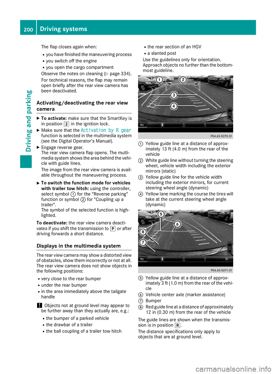
Use the guidelines only for orientation.
Approach objects no further than the bottom-
most guideline.
�C
Yellow guide line at a distance of approx-
imately 13 ft (4.0 m) from the rear of the
vehicle �D
White guide line without turning the steering
wheel, vehicle width including the exterior
mirrors (static) �
Page 217 of 398
Course-correcting brake application If Active Blind Spot Assist detects a risk of a lat-
eral collision in the monitoring range, a course-
correcting brake application is carried out. This
is meant to assist you in avoiding a collision.
G WARNING
A course-correcting brake application cannot
always prevent a collision. There is a risk of an
accident.
Always steer, brake or accelerate yourself,
especially if Active Blind Spot Assist warns
you or makes a course-correcting brake appli-
cation. Always maintain a safe distance at the
sides.
If a course-correcting brake application occurs,
red warning lamp �C flashes in the exterior mir-
ror and a double warning tone sounds. In addi-
tion, a display underlining the danger of a side
collision appears in the multifunction display.
In very rare cases, the system may make an
inappropriate brake application. A course-cor-
recting brake application may be interrupted at
any time by countersteering slightly or acceler-
ating.
The course-correcting brake application is avail-
able in the speed range between 20 mph
(30 km/h) and 120 mph (20 0 km/ h) .
Either no braking application, or a course-cor-
recting brake application adapted to the driving
situation occurs if: R
there are vehicles or obstacles, e.g. crash
barriers, located on both sides of your vehicle. R
a vehicle approaches you too closely at the
side. R
you have adopted a sporty driving style with
high cornering speeds. R
you clearly brake or accelerate. R
a driving safety system intervenes, e.g. ESP ®
or PRE-SAFE ®
Brake.R
ESP ®
is switched off.R
the offroad program is activated (vehicles
without the Offroad Engineering package). R
the Offroad or Offroad Plus drive program is
activated (vehicles with the Off-Road Engi-
neering package). R
the LOW RANGE offroad gear is activated
(vehicles with the Offroad Engineering pack-
age). R
a loss of tire pressure or a defective tire is
detected.
Switching on Active Blind Spot Assist X
Make sure that Active Blind Spot Assist
( Y
page 242) is activated in the on-board
computer. X
Turn the SmartKey to position �H in the igni-
tion lock.
Warning lamps �C in the exterior mirrors light
up red for approximately 1.5 seconds an d
then turn yellow.
Towing a trailer When you attach a trailer, make sure you have
correctly established the electrical connection.
This can be accomplished by checking the trailer
lighting. Active Blind Spot Assist is then deacti-
vated. The indicator lamp lights up yellow in the
exterior mirrors and the Active Blind Spot
Asst. Not Available When Towing a
Trailer See Operator's Manual message
appears in the multifunction display.
Active Lane Keeping Assist
General notes
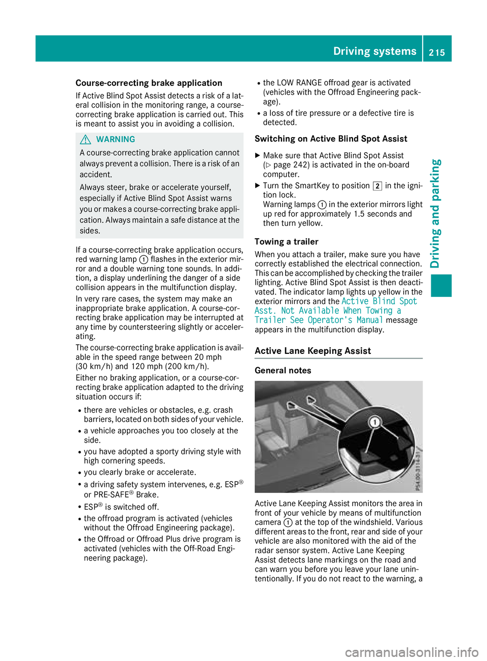
Active Lane Keeping Assist monitors the area in
front of your vehicle by means of multifunction
camera �C at the top of the windshield. Various
different areas to the front, rear and side of your
vehicle are also monitored with the aid of the
radar sensor system. Active Lane Keeping
Assist detects lane markings on the road and
can warn you before you leave your lane unin-
tentionally. If you do not react to the warning, aDriving system s 215
Dr ivi ng an d parking Z
Page 226 of 398
�m
Level control�n
Compass with angle scale
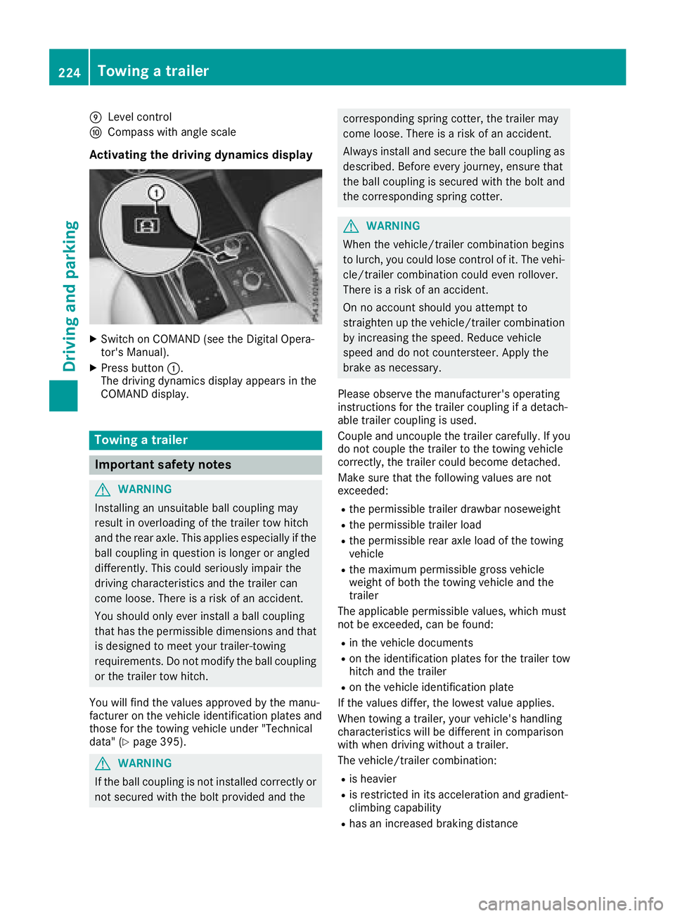
Activating the driving dynamics display X
Switch on COMAND (see the Digital Opera-
tor's Manual). X
Press button �C .
The driving dynamics display appears in the
COMAND display.
Towing a trailer
Important safety notes
G WARNING
Installing an unsuitable ball coupling may
result in overloading of the trailer tow hitch
and the rear axle. This applies especially if the
ball coupling in question is longer or angled
differently. This could seriously impair the
driving characteristics and the trailer can
come loose. There is a risk of an accident.
You should only ever install a ball coupling
that has the permissible dimensions and that
is designed to meet your trailer-towing
requirements. Do not modify the ball coupling
or the trailer tow hitch.
You will find the values approved by the manu-
facturer on the vehicle identification plates and
those for the towing vehicle under "Technical
data" ( Y
page 395).
G WARNING
If the ball coupling is not installed correctly or
not secured with the bolt provided and the corresponding spring cotter, the trailer may
come loose. There is a risk of an accident.
Always install and secure the ball coupling as
described. Before every journey, ensure that
the ball coupling is secured with the bolt and
the corresponding spring cotter.
G WARNING
When the vehicle/trailer combination begins
to lurch, you could lose control of it. The vehi-
cle/trailer combination could even rollover.
There is a risk of an accident.
On no account should you attempt to
straighten up the vehicle/trailer combination
by increasing the speed. Reduce vehicle
speed and do not countersteer. Apply the
brake as necessary.
Please observe the manufacturer's operating
instructions for the trailer coupling if a detach-
able trailer coupling is used.
Couple and uncouple the trailer carefully. If you
do not couple the trailer to the towing vehicle
correctly, the trailer could become detached.
Make sure that the following values are not
exceeded: R
the permissible trailer drawbar noseweight R
the permissible trailer load R
the permissible rear axle load of the towing
vehicle R
the maximum permissible gross vehicle
weight of both the towing vehicle and the
trailer
The applicable permissible values, which must
not be exceeded, can be found: R
in the vehicle documents R
on the identification plates for the trailer tow
hitch and the trailer R
on the vehicle identification plate
If the values differ, the lowest value applies.
When towing a trailer, your vehicle's handling
characteristics will be different in comparison
with when driving without a trailer.
The vehicle/trailer combination: R
is heavier R
is restricted in its acceleration and gradient-
climbing capability R
has an increased braking distance224
Towing a trailer
Driving and parking
Page 227 of 398
R
is affected more by strong crosswinds R
demands more sensitive steering R
has a larger turning circle
This could impair the handling characteristics.
When towing a trailer, always adjust your speed
to the current road and weather conditions. Do
not exceed the maximum permissible speed for
your vehicle/trailer combination.
Notes on towing a trailer
General notes
! If you have a trailer tow hitch retrofitted,
changes to the cooling system and drive train
may be necessary, depending on the vehicle
type.
If you have a trailer tow hitch retrofitted,
observe the anchorage points on the chassis
frame. R
Do not exceed the legally prescribed maxi-
mum speed for vehicle/trailer combinations
in the relevant country.
This lowers the risk of an accident. R
Only install an approved trailer coupling on
your vehicle.
More information on availability and installa-
tion can be obtained at any qualified special-
ist workshop. R
The bumpers of your vehicle are not suitable
for installing detachable trailer couplings. R
Do not install hired trailer couplings or other
detachable trailer couplings on the bumpers
of your vehicle. R
If you no longer need the ball coupling,
remove it from the ball coupling recess. This
will reduce the risk of damage to the ball cou-
pling.
When towing a trailer, set the tire pressure on
the rear axle of the towing vehicle for the max-
imum load. You will find the values in the tire
pressure table in the fuel filler flap of the vehicle
( Y
page 372).
Please note that when towing a trailer, the fol-
lowing driving systems have limited availability
or are not available at all: R
Parking Assist PARKTRONIC ( Y
page 192)R
Blind Spot Assist ( Y
page 209)R
Active Lane Keeping Assist ( Y
page 215) On vehicles without level control, the height of
the ball coupling will alter according to the load
placed on the vehicle. If necessary, use a trailer
with a height-adjustable drawbar.
You will find installing dimensions and loads
under "Technical data" ( Y
page 395).
Driving tips Also observe the notes on pulling away with a
trailer ( Y
page 143).
The maximum permissible speed for vehicle/
trailer combinations depends on the type of
trailer. Before beginning the journey, check the
trailer's documents to see what the maximum
permissible speed is for your trailer. Observe the
legally permissible maximum speed in the rele-
vant country.
For certain Mercedes-Benz vehicles, the maxi-
mum permissible rear axle load is increased
when towing a trailer. See "Technical data" to
find out whether this applies to your vehicle
( Y
page 395). If you utilize any of the added
maximum rear axle load when towing a trailer,
the vehicle/trailer combination may not exceed
a maximum speed of 60 mph (100 km/h) for
reasons concerning the operating permit. This
also applies in countries in which the maximum
permissible speed for car/trailer combinations
is greater than 60 mph (100 km/h).
When towing a trailer, your vehicle's handling
characteristics will be different in comparison
with when driving without a trailer.
Use the left-hand steering wheel paddle shifter
to shift into a lower gear in good time on long
and steep downhill gradients.
This also applies if you have activated cruise
control or Distance Pilot DISTRONIC.
This will use the braking effect of the engine, so
that less braking will be required to maintain the
speed. This relieves the load on the brake sys-
tem and prevents the brakes from overheating
and wearing too quickly. If you need additional
braking, depress the brake pedal repeatedly
rather than continuously.
Driving tips
If the trailer swings from side to side: X
Do not accelerate. X
Do not counter-steer. X
Brake if necessary.Towing a trailer 225
Driving and parking Z
Page 230 of 398
Most U.S. states and all Canadian provinces
require by law: R
Safety chains between the towing vehicle and
the trailer. The chains should be cross-wound
under the trailer drawbar. They must be fas-
tened to the vehicle's trailer coupling, not to
the bumper or the axle.
Leave enough play in the chains to make tight
cornering possible. R
A separate brake system for certain types of
trailer. R
Safety switch for braked trailers. Check the
specific legal requirements applicable to your
state.
If the trailer becomes detached from the tow-
ing vehicle, the safety feature triggers the
trailer brakes.
Towing a trailer There are numerous legal requirements con-
cerning the towing of a trailer, e.g. speed restric-
tions. Make sure that your car/trailer combina-
tion complies with the local regulations: R
in your place of residence R
in the location to which you are driving
The police and local authorities can provide reli-
able information.
Observe the following when towing a trailer: R
To gain driving experience and to become
accustomed to the new handling characteris-
tics, you should practice the following in a
traffic-free location: -
cornering -
stopping -
backing up R
Before driving, check: -
trailer tow hitch -
safety switch for braked trailers -
safety chains -
electrical connections -
lights -
wheels R
Adjust the exterior mirrors to provide an
unobstructed view of the rear section of the
trailer. R
If the trailer has electronically controlled
brakes, pull away carefully. Brake manually using the brake controller and check whether
the brakes function correctly. R
Secure any objects on the trailer to prevent
the cargo from slipping when the vehicle is in
motion. R
When you couple up a trailer, check at regular
intervals that the load is firmly secured. If the
trailer is equipped with trailer lights and
brakes, check the trailer to ensure that these
are working. R
Bear in mind that the handling will be less
stable when towing a trailer than when driving
without one. Avoid sudden steering move-
ments. R
The vehicle/trailer combination is heavier,
accelerates more slowly, has a decreased
gradient climbing capability and a longer
braking distance.
It is more susceptible to side winds and
requires more careful steering. R
If possible, do not brake suddenly, but instead
depress the brake pedal moderately at first so
that the trailer can activate its brakes. Then
increase the pressure on the brake pedal. R
If the automatic transmission repeatedly
shifts between gears on uphill or downhill gra-
dients, shift to a lower gear using the left-hand
steering wheel paddle shifter.
A lower gear and lower speed reduce the risk
of engine failure. R
When driving downhill, shift to a lower gear to
utilize the engine's braking effect.
Avoid continuous brake application as this
may overheat the vehicle brakes and, if instal-
led, the trailer brakes. R
If the coolant temperature increases dramat-
ically while the air-condition ing system is
switched on, switch off the air-conditioning
system.
Coolant heat can also be dissipated by open-
ing the windows and switching the ventilation
blower and the interior temperature to the
highest level. R
When overtaking, pay particular attention to
the extended length of your vehicle/trailer
combination.
Due to the length of the vehicle/trailer com-
bination, you require additional road space in
relation to the vehicle you are overtaking
before you can change back to the original
lane.228
Towing a trailer
Driving and parking
Page 231 of 398
Decoupling a trailer
G WARNING
If you uncoupl e a trailer wit h th e overrun
brake engaged, you could trap your han d
between th e vehicle and th e trailer drawbar .
There is a ris k of injury.
Do no t uncoupl e a trailer if th e overrun brake
is engaged.
G WARNING
Vehicles wit h level control:
The vehicle is lowered as soo n as you discon-
nect th e trailer cable. Thi s could result in your
limbs or those of other people that are
between th e vehicle bod y and tires or under-
neat h th e vehicle bein g trapped. There is a
ris k of injury.
Mak e sur e that nobod y is in th e immediate
vicinit y of th e whee l housings or under th e
vehicle when you disconnec t th e trailer cable.
! Do no t disconnec t a trailer wit h an engage d
overrun brake . Otherwise , your vehicle could
be damaged by th e reboundin g of th e overrun
brake .X
Shift th e transmissio n to position P .X
Apply th e vehicle' s electric parking brake .X
Start th e engine.X
Clos e th e doors and tailgate.X
Apply th e trailer's parking brake .X
Detach th e trailer cable and decoupl e th e
trailer .X
Switc h of f th e engine.
Permissible trailer loads an d drawbar
loads
Weight specifications
Maximum allowable gross mass
The gross vehicle weight of th e trailer is calcu-
lated by addin g th e weight of th e trailer to th e
weight of th e load and equipmen t on th e trailer .
You will fin d installin g dimensions and load s
under "Technical data" ( Y
page 395). Permissible noseweigh tYou will fin d installin g dimensions and load s
under "Technical data" ( Y
page 395).
Loading a trailer R
Whe n loadin g th e trailer , mak e sur e that nei-
ther th e permissible gross weight of th e trailer
no r th e gross vehicle weight are exceeded.
The permissible gross vehicle weight is indi-
cated on th e identification plat e located on
th e B-pilla r on th e driver's sid e of th e vehicle.
You can fin d th e maximum permissible values
on th e typ e plates of your vehicle and th e
trailer . Whe n calculatin g how muc h weight
th e vehicle and trailer may carry, pay atten-
tion to th e respective lowest values. R
The trailer drawbar load on th e ball couplin g
mus t be adde d to th e rea r axl e load to avoid
exceedin g th e permissible gross axl e weight .
The permissible gross vehicle weight is indi-
cated on th e identification plat e located on
th e B-pilla r on th e driver's sid e of th e vehicle.
i Mercedes-Ben z recommends a trailer load
wher e th e trailer drawbar noseweigh t
accounts fo r 8 % to 15 % of th e trailer's per -
missible gross weight .
i The weight of additional accessories , pas-
sengers, and cargo reduce s th e permissible
trailer load and drawbar load fo r your vehicle.
Checking th e vehicle an d trailer weigh tR
To chec k that th e weight s of th e towin g vehi-
cl e and th e trailer compl y wit h th e maximum
permissible values, hav e th e vehicle/trailer
combination (includin g th e driver , passen -
gers, and cargo wit h a full y lade n trailer )
weighed on a calibrated weighbridge .R
Chec k th e gross axl e weight ratin g of th e fron t
and rea r axles, th e gross weight of th e trailer
and th e trailer drawbar noseweight.
Removin g th e ball coupling X
Remov e th e sprin g cotter.X
Remov e th e bolt from th e ball couplin g
recess . X
Remov e th e ball couplin g from th e ball cou-
plin g recess .Towing a trailer 229
Driving and parking Z