2018 MERCEDES-BENZ GLE SUV tightening
[x] Cancel search: tighteningPage 26 of 398

Vehicle batterysee Battery (vehicle)
Vehicle data ....................................... 390
Vehicle data (off-road driving)
Approach/departure angle ............ 393
Fording depth ................................ 392
Maximum gradient climbing abil-
ity .................................................. 393
Vehicle dimensions ........................... 390
Vehicle emergency locking ................ 84
Vehicle identification number
see VIN
Vehicle identification plate .............. 382
Vehicle level
AIRMATIC ...................................... 185
Vehicle level (display message) ....... 260
Vehicle tool kit .................................. 335
Video
Operating the DVD ......................... 234
see also Digital Operator's Man-
ual .................................................. 287
VIN ...................................................... 382
Seat ............................................... 383
Type plate ...................................... 382
W
Warning and indicator lamps ABS ................................................ 277
Brakes ........................................... 276
Coolant .......................................... 283
Distance Pilot DISTRONIC ............. 285
Distance warning ........................... 285
Engine diagnostics ......................... 283
ESP
®.............................................. 279
ESP®OFF ....................................... 280
Fuel tank ........................................ 283
Overview .......................................... 37
Parking brake ................................ 282
PASSENGER AIR BAG ...................... 45
Reserve fuel ................................... 283
Restraint system ............................ 282
Seat belt ........................................ 274
Tire pressure monitor .................... 286
Warranty .............................................. 28
Washer fluid
Display message ............................ 272 Weather display (COMAND)
see also Digital Operator's Man-
ual .................................................. 287
Wheel and tire combinations
Tires ............................................... 376
Wheel bolt tightening torque ........... 375
Wheel chock ...................................... 372
Wheels
Changing a wheel .......................... 371
Checking ........................................ 351
Cleaning ......................................... 329
Emergency spare wheel ................. 376
Important safety notes .................. 351
Information on driving .................... 351
Interchanging/changing ................ 371
Mounting a new wheel ................... 374
Mounting a wheel .......................... 372
Overview ........................................ 351
Removing a wheel .......................... 374
Snow chains .................................. 353
Storing ........................................... 372
Tightening torque ........................... 375
Wheel size/tire size ....................... 376
Window curtain air bag
Display message ............................ 252
Operation ......................................... 51
Windows
see Side windows
Windshield
Defrosting ...................................... 129
Infrared reflective .......................... 320
Windshield washer fluid
see Windshield washer system
Windshield washer system
Adding washer fluid ....................... 325
Important safety notes .................. 389
Windshield wipers
Problem (malfunction) ................... 121
Rear window wiper ........................ 118
Replacing the wiper blades ............ 118
Rep
lacing the wiper blades
(MAGIC VISION CONTROL) ............ 119
Switching on/off ........................... 117
Winter driving
Slippery road surfaces ................... 164
Winter operation
Overview ........................................ 353
Radiator cover ............................... 322
24Index
Page 50 of 398

Fastening and adjusting the seat belts
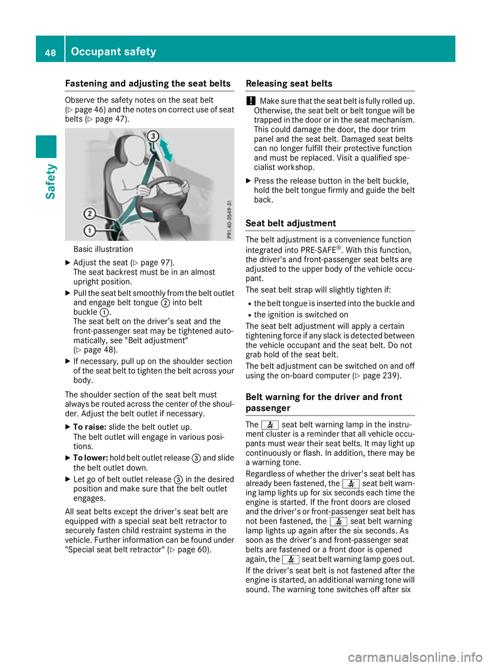
Observeth esafet ynote son th eseat belt
(Ypage 46) and th enote son correct use of seat
belt s (Ypage 47) .
Basic illustration
XAdjustth eseat (Ypage 97).
The seat backrest must be in an almost
upright position .
XPull theseat belt smoothly from th ebelt outlet
and engage belt tongue ;intobelt
buckle :.
The seat belt on th edriver’s seat and th e
front-passenger seat may be tightened auto -
matically, see "Belt adjustment"
(
Ypage 48).
XIf necessary, pull up on th eshoulder section
of th eseat belt to tighten th ebelt across your
body.
The shoulder section of th eseat belt must
always be routed across th ecente rof th eshoul-
der .Adjus tth ebelt outlet if necessary.
XTo raise: slide thebelt outlet up.
The belt outlet will engage in various posi-
tions.
XTo lower :hold belt outlet release =and slide
th ebelt outlet down .
XLet go of belt outlet release =in th edesired
position and mak esure that th ebelt outlet
engages.
All seat belt sexcep tth edriver' sseat belt are
equipped wit h aspecial seat belt retracto rto
securel yfaste nchild restrain tsystems in th e
vehicle. Further information can be foun dunder
"Special seat belt retractor" (
Ypage 60).
Releasing seat belts
!Makesure that th eseat belt is fully rolled up.
Otherwise, th eseat belt or belt tongue will be
trapped in th edoor or in th eseat mechanism .
This could damag eth edoor ,th edoor trim
panel and th eseat belt .Damaged seat belt s
can no longer fulfill their protective function
and must be replaced. Visit aqualified spe-
cialist workshop.
XPress th erelease butto nin th ebelt buckle,
hold th ebelt tongue firmly and guide th ebelt
back.
Seat belt adjustment
The belt adjustmen tis aconvenience function
integrate dint oPRE-SAF E®.Wit hthis function ,
th edriver' sand front-passenger seat belt sare
adjusted to th eupper body of th evehicl eoccu-
pant.
The seat belt strap will slightly tighten if:
Rth ebelt tongue is inserted int oth ebuckle and
Rth eignition is switched on
The seat belt adjustmen twill apply acertai n
tightening force if any slac kis detected between
th evehicl eoccupant and th eseat belt .Do no t
grab hold of th eseat belt .
The belt adjustmen tcan be switched on and off
usin gth eon-board computer (
Ypage 239).
Belt warning for the driver and front
passenger
The7 seat belt warning lamp in th einstru-
men tcluste ris areminder that all vehicl eoccu-
pants must wear their seat belts. It may ligh tup
continuously or flash. In addition ,there may be
a warning tone .
Regardles sof whether th edriver' sseat belt has
already been fastened, th e7 seat belt warn -
ing lamp lights up for six seconds eac htime th e
engin eis started. If th efron tdoor sare closed
and th edriver' sor front-passenger seat belt has
no tbeen fastened, th e7 seat belt warning
lamp lights up again after th esix seconds. As
soo nas th edriver' sand front-passenger seat
belt sare fastene dor afron tdoor is opened
again ,th e7 seat belt warning lamp goes out .
If th edriver' sseat belt is no tfastene dafter th e
engin eis started, an additional warning tone will
sound. The warning tone switches off after six
48Occupant safety
Safety
Page 59 of 398

repaired. This will help to make sure the air bags
continue to perform their protective function for
the vehicle occupants in the event of a crash.
GWARNING
Emergency Tensioning Devices that have
deployed pyrotechnically are no longer opera-
tional and are unable to perform their inten-
ded protective function. This poses an
increased risk of injury or even fatal injury.
Have pyrotechnically triggered Emergency
Tensioning Devices replaced immediately at a
qualified specialist workshop.
An electric motor is used by PRE-SAFE
®to trig-
ger the tightening of the seat belt in hazardous
situations. This procedure is reversible.
If Emergency Tensioning Devices are triggered
or air bags are deployed, you will hear a bang,
and some powder may also be released. The
6 restraint system warning lamp lights up.
Only in rare cases will the bang affect your hear-
ing. The powder that is released generally does
not constitute a health hazard, but it may cause short-term breathing difficulties in people with
asthma or other respiratory problems. Provided
it is safe to do so, you should leave the vehicle
immediately or open the window in order to pre-
vent breathing difficulties.
Air bags and pyrotechnic Emergency Tensioning
Devices (ETDs) contain perchlorate material,
which may require special handling and regard
for the environment. National guidelines must
be observed during disposal. In California, see
www.dtsc.ca.gov/HazardousWaste/
Perchlorate/index.cfm.
Method of operation
During the first stage of a collision, the restraint
system control unit evaluates important physi-
cal data relating to vehicle deceleration or accel-
eration, such as:
Rduration
Rdirection
Rintensity
Based on the evaluation of this data, the
restraint system control unit triggers the Emer-
gency Tensioning Devices during a frontal or
rear collision. An Emergency Tensioning Device can only be
triggered, if:
Rthe ignition is switched on
Rthe components of the restraint system are
operational. You can find further information
under "Restraint system warning lamp"
(
Ypage 45)
Rthe seat belt buckle tongue has engaged in
the belt buckle of the respective front seat
The Emergency Tensioning Devices in the rear
compartment are triggered independently of the
lock status of the seat belts.
If the restraint system control unit detects a
more severe accident, further components of
the restraint system are activated independ-
ently of each other in certain frontal collision
situations:
RFront air bags and driver's knee bag
RWindow curtain air bag, if the system deter-
mines that deployment can offer additional
protection to that provided by the seat belt
The front-passenger front air bag is activated or
deactivated depending on the person on the
front-passenger seat. The front-passenger front
air bag can only deploy in an accident if the
PASSENGER AIR BAG OFF indicator lamp is off.
Observe the information on the PASSENGER AIR
BAG indicator lamps (
Ypage 45).
Your vehicle has two-stage front air bags. In the
first deployment stage, the front air bag is filled
with propellant gas. The front air bag is fully
deployed with the maximum amount of propel-
lant gas if a second deployment threshold is
reached within a few milliseconds.
The activation threshold of the Emergency Ten-
sioning Devices and the air bags is determined
by evaluating the rate of vehicle decelera
tion or
acceleration which occurs at various points in
the vehicle. This process is pre-emptive in
nature. Deployment should take place in good
time at the start of the collision.
The rate of vehicle deceleration or acceleration
and the direction of the force are essentially
determined by:
Rthe distribution of forces during the collision
Rthe collision angle
Rthe deformation characteristics of the vehicle
Rthe characteristics of the object with which
the vehicle has collided
Factors which can only be seen and measured
after a collision has occurred do not play a deci-
sive role in the deployment of an air bag. Nor do
Occupant safety57
Safety
Z
Page 377 of 398

only use wheel bolts which have been approved
for Mercedes-Benz vehicles and the respective
wheel.
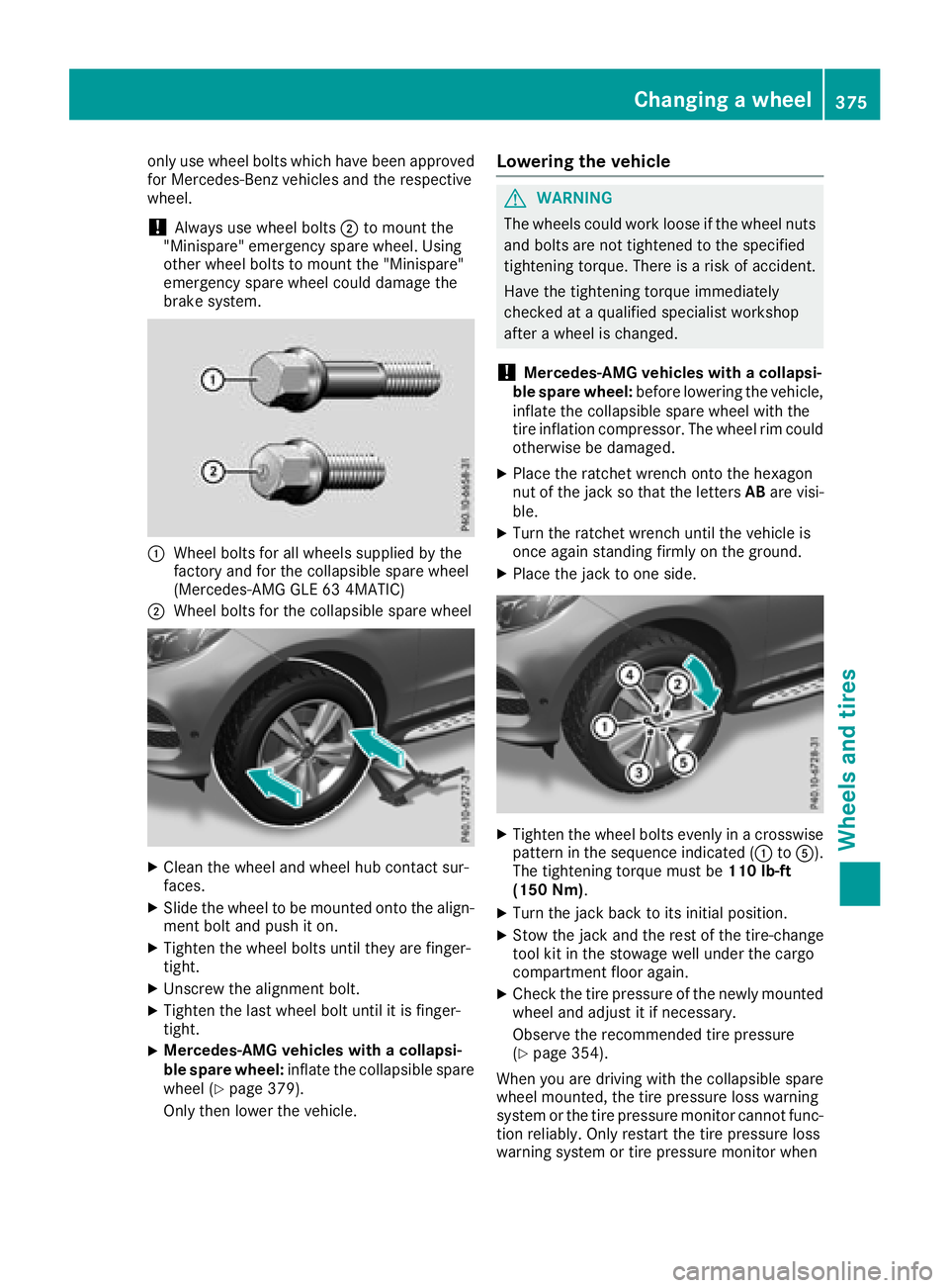
!Always use wheel bolts;to mount the
"Minispare" emergency spare wheel. Using
other wheel bolts to mount the "Minispare"
emergency spare wheel could damage the
brake system.
:Wheel bolts for all wheels supplied by the
factory and for the collapsible spare wheel
(Mercedes-AMG GLE 63 4MATIC)
;Wheel bolts for the collapsible spare wheel
XClean the wheel and wheel hub contact sur-
faces.
XSlide the wheel to be mounted onto the align-
ment bolt and push it on.
XTighten the wheel bolts until they are finger-
tight.
XUnscrew the alignment bolt.
XTighten the last wheel bolt until it is finger-
tight.
XMercedes-AMG vehicles with a collapsi-
ble spare wheel: inflate the collapsible spare
wheel (
Ypage 379).
Only then lower the vehicle.
Lowering the vehicle
GWARNING
The wheels could work loose if the wheel nuts and bolts are not tightened to the specified
tightening torque. There is a risk of accident.
Have the tightening torque immediately
checked at a qualified specialist workshop
after a wheel is changed.
!Mercedes-AMG vehicles with a collapsi-
ble spare wheel: before lowering the vehicle,
inflate the collapsible spare wheel with the
tire inflation compressor. The wheel rim could
otherwise be damaged.
XPlace the ratchet wrench onto the hexagon
nut of the jack so that the letters ABare visi-
ble.
XTurn the ratchet wrench until the vehicle is
once again standing firmly on the ground.
XPlace the jack to one side.
XTighten the wheel bolts evenly in a crosswise pattern in the sequence indicated (: toA).
The tightening torque must be 110 lb-ft
(150 Nm).
XTurn the jack back to its initial position.
XStow the jack and the rest of the tire-change
tool kit in the stowage well under the cargo
compartment floor again.
XCheck the tire pressure of the newly mounted
wheel and adjust it if necessary.
Observe the recommended tire pressure
(
Ypage 354).
When you are driving with the collapsible spare
wheel mounted, the tire pressure loss warning
system or the tire pressure monitor cannot func-
tion reliably. Only restart the tire pressure loss
warning system or tire pressure monitor when
Changing a wheel375
Wheels and tires
Z