2018 MERCEDES-BENZ GLE SUV tow
[x] Cancel search: towPage 365 of 398
able cargo and luggage load capacity is
650 lbs (1400 - 750 (5 x 150) = 650 lbs).
XStep 5:Determine the combined weight of
luggage and cargo being loaded on the vehi- cle. That weight may not safely exceed the
available cargo and luggage load capacity cal-
culated in step 4.
Example: steps 1 to 3
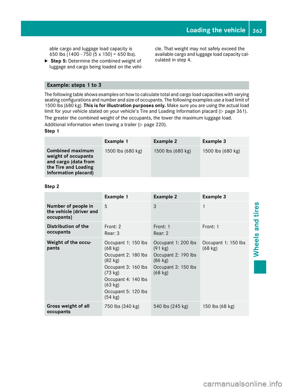
The following table shows examples on how to calculate total and cargo load capacities with varying
seating configurations and number and size of occupants. The following examples use a load limit of
1500 lbs (680 kg).
This is for illustration purposes only. Make sure you are using the actual load
limit for your vehicle stated on your vehicle's Tire and Loading Information placard (
Ypage 361).
The greater the combined weight of the occupants, the lower the maximum luggage load.
Additional information when towing a trailer (
Ypage 220).
Step 1
Example 1Example 2Example 3
Combined maximum
weight of occupants
and cargo (data from
the Tire and Loading
Information placard)1500 lbs (680 kg)1500 lbs (680 kg)1500 lbs (680 kg)
Step 2
Example 1Example 2Example 3
Number of people in
the vehicle (driver and
occupants)531
Distribution of the
occupantsFront: 2
Rear: 3Front: 1
Rear: 2Front: 1
Weight of the occu-
pantsOccupant 1: 150 lbs
(68 kg)
Occupant 2: 180 lbs
(82 kg)
Occupant 3: 160 lbs
(73 kg)
Occupant 4: 140 lbs
(63 kg)
Occupant 5: 120 lbs
(54 kg)Occupant 1: 200 lbs
(91 kg)
Occupant 2: 190 lbs
(86 kg)
Occupant 3: 150 lbs
(68 kg)Occupant 1: 150 lbs
(68 kg)
Gross weight of all
occupants750 lbs (340 kg)540 lbs (245 kg)150 lbs (68 kg)
Loading the vehicle363
Wheels and tires
Z
Page 373 of 398
Sidewall
The part of the tire between the tread and the
bead.
Weight of optional extras
The combined weight of those optional extras
that weigh more than the replaced standard
parts and more than 2.3 kg (5 lbs). These
optional extras, such as high-performance
brakes, level control, a roof rack or a high-per-
formance battery, are not included in the curb
weight and the weight of the accessories.
TIN (Tire Identification Number)
This is a unique identifier which can be used by
a tire manufacturer to identify tires, for example
for a product recall, and thus identify the pur-
chasers. The TIN is made up of the manufactur-
er's identity code, tire size, tire type code and
the manufacturing date.
Load bearing index
The load bearing index (also load index) is a code
that contains the maximum load bearing capa-
city of a tire.
Traction
Traction is the result of friction between the tires
and the road surface.
TWR (Tongue Weight Rating)
The TWR specifies the maximum permissible
weight that the ball coupling of the trailer tow
hitch can support.
Treadwear indicators
Narrow bars (tread wear bars) that are distrib-
uted over the tire tread. If the tire tread is level
with the bars, the wear limit ofáin (1.6 mm)
has been reached.
Occupant distribution
The distribution of occupants in a vehicle at their
designated seating positions.
Total load limit
Nominal load and luggage load plus 68 kg
(150 lbs) multiplied by the number of seats in
the vehicle.
Changing a wheel
Flat tire
The "Breakdown assistance" section
(Ypage 335) contains information and notes on
how to deal with a flat tire. Information on driv-
ing with MOExtended tires in the event of a flat
tire can be found under "MOExtended tires (tires
with run-flat characteristics" (
Ypage 336).
Vehicles with an emergency spare wheel: in
the event of a flat tire, mount the emergency
spare wheel according to the description under "Mounting a wheel" (
Ypage 372).
Rotating the wheels
GWARNING
Interchanging the front and rear wheels may
severely impair the driving characteristics if
the wheels or tires have different dimensions. The wheel brakes or suspension components
may also be damaged. There is a risk of acci-
dent.
Rotate front and rear wheels only if the wheels and tires are of the same dimensions.
!On vehicles equipped with a tire pressure
monitor, electronic components are located
in the wheel.
Tire-mounting tools should not be used near
the valve. This could damage the electronic
components.
Only have tires changed at a qualified spe-
cialist workshop.
Always observe the instructions and safety
notes in the "Mounting a wheel" section
(
Ypage 372).
The wear patterns on the front and rear tires
differ, depending on the operating conditions.
Rotate the wheels before a clear wear pattern
has formed on the tires. Front tires typically
wear more on the shoulders and the rear tires in
the center.
On vehicles that have the same size front and
rear wheels, you can rotate the wheels accord-
ing to the intervals in the tire manufacturer's
warranty book in your vehicle documents. If no
warranty book is available, the tires should be
rotated every 3,000 to 6,000 miles (5,000 to
10,000 km). Depending on tire wear, this may
Changing a wheel371
Wheels and tires
Z
Page 377 of 398
only use wheel bolts which have been approved
for Mercedes-Benz vehicles and the respective
wheel.
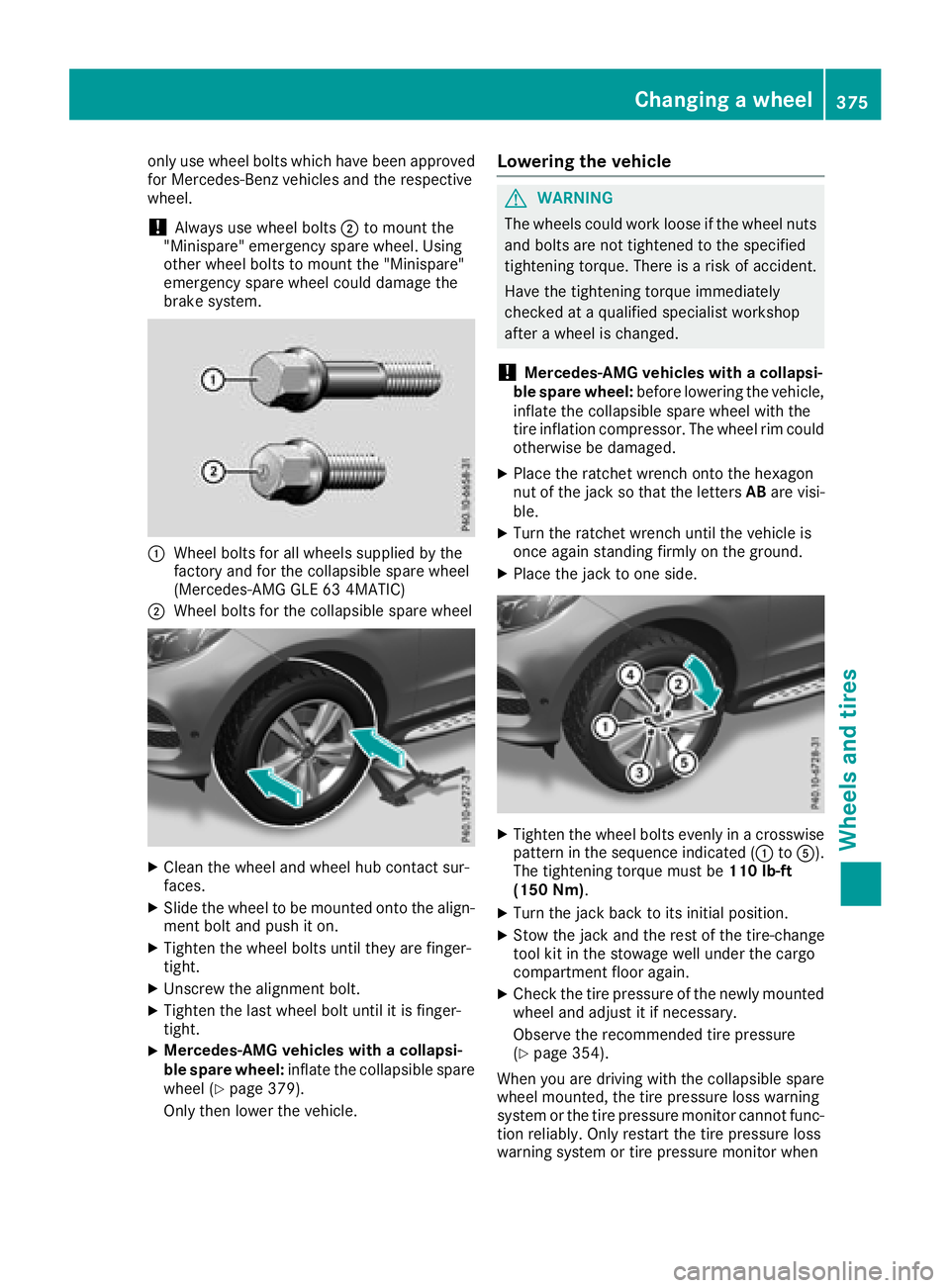
!Always use wheel bolts;to mount the
"Minispare" emergency spare wheel. Using
other wheel bolts to mount the "Minispare"
emergency spare wheel could damage the
brake system.
:Wheel bolts for all wheels supplied by the
factory and for the collapsible spare wheel
(Mercedes-AMG GLE 63 4MATIC)
;Wheel bolts for the collapsible spare wheel
XClean the wheel and wheel hub contact sur-
faces.
XSlide the wheel to be mounted onto the align-
ment bolt and push it on.
XTighten the wheel bolts until they are finger-
tight.
XUnscrew the alignment bolt.
XTighten the last wheel bolt until it is finger-
tight.
XMercedes-AMG vehicles with a collapsi-
ble spare wheel: inflate the collapsible spare
wheel (
Ypage 379).
Only then lower the vehicle.
Lowering the vehicle
GWARNING
The wheels could work loose if the wheel nuts and bolts are not tightened to the specified
tightening torque. There is a risk of accident.
Have the tightening torque immediately
checked at a qualified specialist workshop
after a wheel is changed.
!Mercedes-AMG vehicles with a collapsi-
ble spare wheel: before lowering the vehicle,
inflate the collapsible spare wheel with the
tire inflation compressor. The wheel rim could
otherwise be damaged.
XPlace the ratchet wrench onto the hexagon
nut of the jack so that the letters ABare visi-
ble.
XTurn the ratchet wrench until the vehicle is
once again standing firmly on the ground.
XPlace the jack to one side.
XTighten the wheel bolts evenly in a crosswise pattern in the sequence indicated (: toA).
The tightening torque must be 110 lb-ft
(150 Nm).
XTurn the jack back to its initial position.
XStow the jack and the rest of the tire-change
tool kit in the stowage well under the cargo
compartment floor again.
XCheck the tire pressure of the newly mounted
wheel and adjust it if necessary.
Observe the recommended tire pressure
(
Ypage 354).
When you are driving with the collapsible spare
wheel mounted, the tire pressure loss warning
system or the tire pressure monitor cannot func-
tion reliably. Only restart the tire pressure loss
warning system or tire pressure monitor when
Changing a wheel375
Wheels and tires
Z
Page 379 of 398
Ronly use a spare wheel or emergency spare
wheel of a different size briefly.
Rdo not switch ESP®off.
Rhave a spare wheel or emergency spare
wheel of a different size replaced at the
nearest qualified specialist workshop.
Observe that the wheel and tire dimensions
as well as the tire type must be correct.
!Mercedes-AMG vehicles with
"Minispare" emergency spare wheel: only
use the "Minispare" emergency spare wheel
on the rear axle. If you mount the
"Minispare" emergency spare wheel on the
front axle, this could result in damage to the
brake system.
If a tire on the front axle is defective, an intact
wheel from the rear axle must first be
replaced with the "Minispare" emergency
spare wheel. The damaged wheel on the front
axle can then be replaced by the undamaged
wheel from the rear axle.
Make sure to note the placard on the
"Minispare" emergency spare wheel.
When using an emergency spare wheel or spare
wheel of a different size, you must not exceed
the maximum speed of 50 mph (80 km/h) .
You should regularly check the pressure of the
emergency spare wheel, particularly prior to
long trips, and correct the pressure as neces-
sary (
Ypage 354). The value on the wheel is
valid.
Snow chains must not be mounted on emer-
gency spare wheels.
General notes
Information regarding permitted emergency
spare wheels can be found at an authorized
Mercedes-Benz Center.
Mounting the emergency spare wheel is descri- bed under "Mounting a wheel" (
Ypage 372).
An emergency spare wheel may also be moun-
ted against the direction of rotation. Observe
the time restriction on use as well as the speed
limitation specified on the emergency spare
wheel.
Replace the tires after six years at the latest,
regardless of wear. This also applies to the
emergency spare wheel. When you are driving with the collapsible spare
wheel mounted, the tire pressure loss warning
system or the tire pressure monitor cannot func-
tion reliably. Only restart the tire pressure loss
warning system or tire pressure monitor when
the defective wheel has been replaced with a
new wheel.
Vehicles with tire pressure monitor: after
mounting an emergency spare wheel, the sys-
tem may still display the tire pressure of the
removed wheel for a few minutes. The value dis-
played for the mounted emergency spare wheel
is not the same as the current tire pressure of
the emergency spare wheel.
Removing/stowing the emergency
spare wheel
Vehicles with a "Minispare" emergency
spare wheel under the cargo compart-
ment floor
Always observe the instructions and safety
notes in the "Mounting a wheel" section
(
Ypage 372).
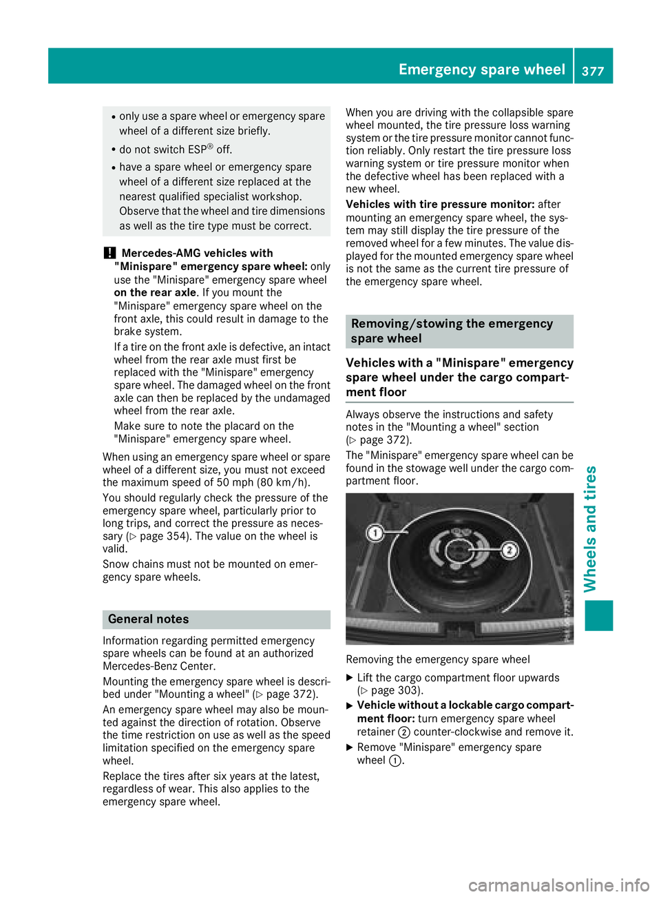
The "Minispare" emergency spare wheel can be
found in the stowage well under the cargo com-
partment floor.
Removing the emergency spare wheel
XLift the cargo compartment floor upwards
(Ypage 303).
XVehicle without a lockable cargo compart-
ment floor: turn emergency spare wheel
retainer ;counter-clockwise and remove it.
XRemove "Minispare" emergency spare
wheel :.
Emergency spare wheel377
Wheels and tires
Z
Page 380 of 398
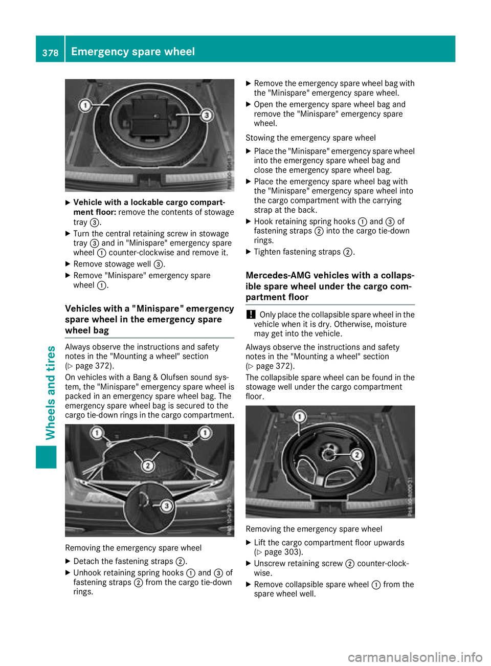
XVehicle with a lockable cargo compart-
ment floor:remove the contents of stowage
tray =.
XTurn the central retaining screw in stowage
tray=and in "Minispare" emergency spare
wheel :counter-clockwise and remove it.
XRemove stowage well =.
XRemove "Minispare" emergency spare
wheel:.
Vehicles with a "Minispare" emergency
spare wheel in the emergency spare
wheel bag
Always observe the instructions and safety
notes in the "Mounting a wheel" section
(
Ypage 372).
On vehicles with a Bang & Olufsen sound sys-
tem, the "Minispare" emergency spare wheel is
packed in an emergency spare wheel bag. The
emergency spare wheel bag is secured to the
cargo tie-down rings in the cargo compartment.
Removing the emergency spare wheel
XDetach the fastening straps ;.
XUnhook retaining spring hooks :and =of
fastening straps ;from the cargo tie-down
rings.
XRemove the emergency spare wheel bag with the "Minispare" emergency spare wheel.
XOpen the emergency spare wheel bag and
remove the "Minispare" emergency spare
wheel.
Stowing the emergency spare wheel
XPlace the "Minispare" emergency spare wheel
into the emergency spare wheel bag and
close the emergency spare wheel bag.
XPlace the emergency spare wheel bag with
the "Minispare" emergency spare wheel into
the cargo compartment with the carrying
strap at the back.
XHook retaining spring hooks :and =of
fastening straps ;into the cargo tie-down
rings.
XTighten fastening straps ;.
Mercedes-AMG vehicles with a collaps-
ible spare wheel under the cargo com-
partment floor
!Only place the collapsible spare wheel in the
vehicle when it is dry. Otherwise, moisture
may get into the vehicle.
Always observe the instructions and safety
notes in the "Mounting a wheel" section
(
Ypage 372).
The collapsible spare wheel can be found in the
stowage well under the cargo compartment
floor.
Removing the emergency spare wheel
XLift the cargo compartment floor upwards
(Ypage 303).
XUnscrew retaining screw ;counter-clock-
wise.
XRemove collapsible spare wheel :from the
spare wheel well.
378Emergency spare wheel
Wheels and tires
Page 381 of 398

Inflating the collapsible spare wheel
(Ypage 379).
Take the following steps to stow a used collaps- ible spare wheel. Otherwise, it will not fit into the
spare wheel well. Mercedes-Benz recommends
that you have this work performed at a qualified
specialist workshop, e.g. at an authorized
Mercedes-Benz Center.
Stowing the emergency spare wheel
XUnscrew the valve cap from the valve.
XIf possible, unscrew the valve insert from the
valve and release the air.
iFully deflating the tires can take a few
minutes.
XScrew the valve insert back into the valve.
XScrew the valve cap back on.
XLay collapsible spare wheel :in the emer-
gency spare wheel well.
XScrew in retaining screw ;clockwise in the
collapsible spare wheel to the stop.
XSwing the cargo compartment floor down
(Ypage 303).
Mercedes-AMG vehicles with a collaps-
ible spare wheel in the emergency
spare wheel bag
Always observe the instructions and safety
notes in the "Mounting a wheel" section
(
Ypage 372).
On Mercedes-AMG vehicles with a Bang & Oluf-
sen sound system, the collapsible spare wheel is
packed in an emergency spare wheel bag. The
emergency spare wheel bag is secured to the
cargo tie-down rings in the cargo compartment.
Removing the emergency spare wheel
XUnhook retaining spring hooks :of fasten-
ing strap ;from the cargo tie-down rings.
XRemove the emergency spare wheel bag with
the emergency collapsible spare wheel.
XOpen the bag and remove the emergency col-
lapsible spare wheel.
Inflating the collapsible spare wheel
(
Ypage 379).
Stowing the emergency spare wheel
XPlace the collapsible spare wheel into the
emergency spare wheel bag and close the
emergency spare wheel bag.
XPlace the emergency spare wheel bag with
the collapsible spare wheel into the cargo
compartment with the carrying strap at the
back.
XHook retaining spring hooks :of fastening
strap ;into the cargo tie-down rings.
XTighten fastening strap ;.
Inflating the collapsible spare wheel
(Mercedes-AMG GLE 63 4MATIC)
!
Inflate the collapsible spare wheel using the
tire inflation compressor before lowering the
vehicle. The wheel rim could otherwise be
damaged.
!Do not operate the tire inflation compressor
for longer than eight minutes at a time without
a break. It may otherwise overheat.
The tire inflation compressor can be operated
again once it has cooled down.
Comply with the manufacturer's safety instruc-
tions on the tire inflation compressor label and
on the tire sealant bottle.
XMount the collapsible spare wheel as descri-
bed (Ypage 372).
The collapsible spare wheel must be mounted before it is inflated.
XRemove the tire inflation compressor from
the stowage space under the cargo compart-
ment floor (
Ypage 335).
Emergency spare wheel379
Wheels and tires
Z
Page 382 of 398
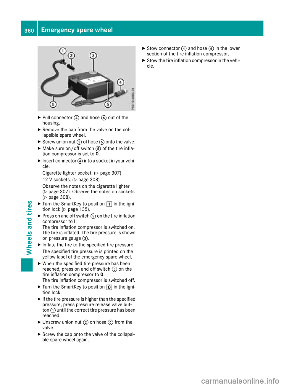
XPull connector?and hose Bout of the
housing.
XRemove the cap from the valve on the col-
lapsible spare wheel.
XScrew union nut ;of hose Bonto the valve.
XMake sure on/off switch Aof the tire infla-
tion compressor is set to 0.
XInsert connector?into a socket in your vehi-
cle.
Cigarette lighter socket: (
Ypage 307)
12 V sockets: (
Ypage 308)
Observe the notes on the cigarette lighter
(
Ypage 307). Observe the notes on sockets
(Ypage 308).
XTurn the SmartKey to position 1in the igni-
tion lock (Ypage 135).
XPress on and off switch Aon the tire inflation
compressor to I.
The tire inflation compressor is switched on.
The tire is inflated. The tire pressure is shown
on pressure gauge =.
XInflate the tire to the specified tire pressure.
The specified tire pressure is printed on the
yellow label of the emergency spare wheel.
XWhen the specified tire pressure has been
reached, press on and off switch Aon the
tire inflation compressor to 0.
The tire inflation compressor is switched off.
XTurn the SmartKey to position uin the igni-
tion lock.
XIf the tire pressure is higher than the specified
pressure, press pressure release valve but-
ton :until the correct tire pressure has been
reached.
XUnscrew union nut ;on hose Bfrom the
valve.
XScrew the cap onto the valve of the collapsi-
ble spare wheel again.
XStow connector ?and hose Bin the lower
section of the tire inflation compressor.
XStow the tire inflation compressor in the vehi-
cle.
380Emergency spare wheel
Wheels and tires
Page 396 of 398
For further information about the maximum gra-
dient climbing ability, see (Ypage 168).
Trailer tow hitch
Mounting dimensions
!
If you have a trailer tow hitch retrofitted,
changes to the cooling system and drive train
may be necessary, depending on the vehicle
type.
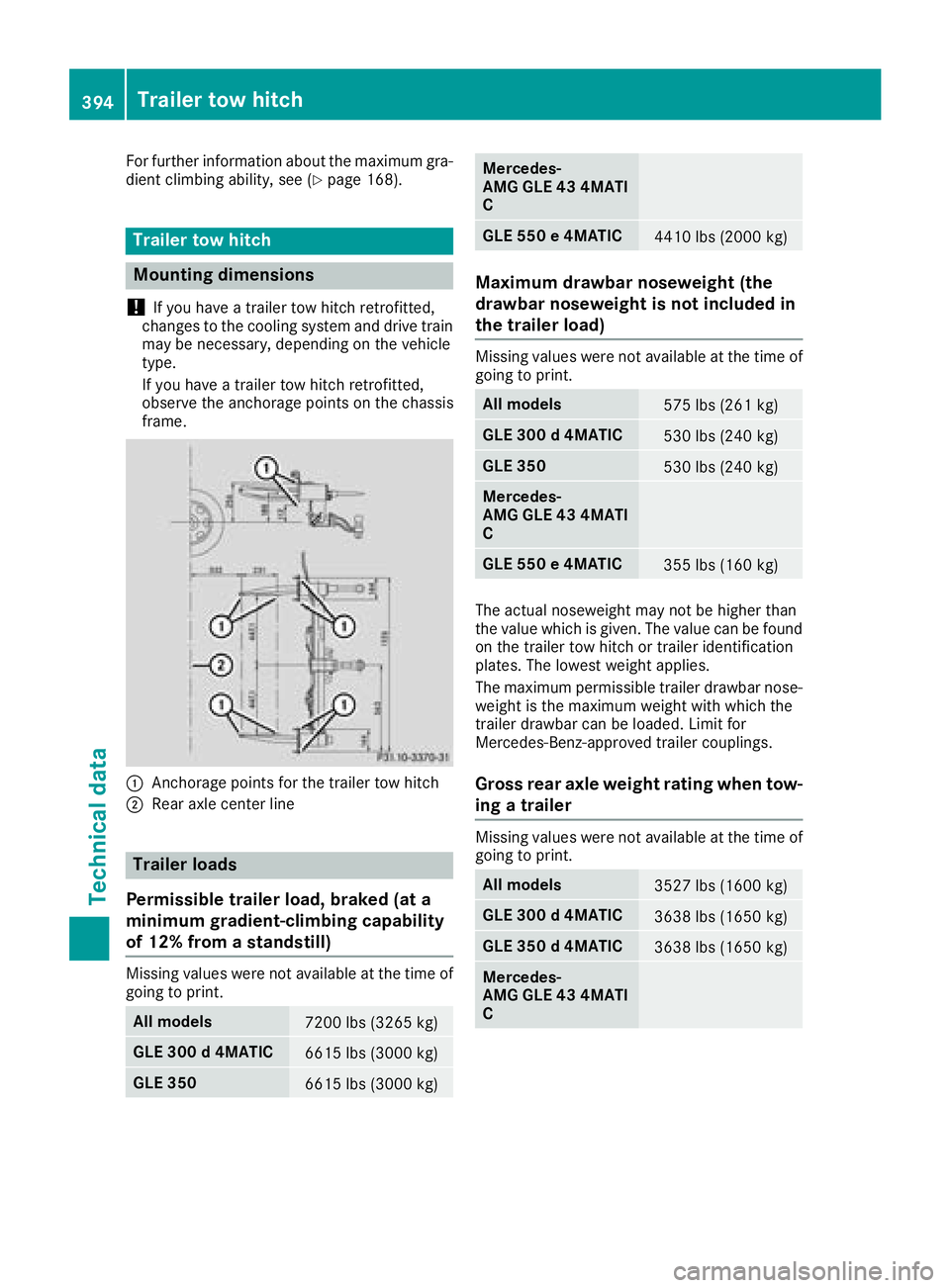
If you have a trailer tow hitch retrofitted,
observe the anchorage points on the chassis
frame.
:Anchorage points for the trailer tow hitch
;Rear axle center line
Trailer loads
Permissible trailer load, braked (at a
minimum gradient-climbing capability
of 12% from a standstill)
Missing values were not available at the time of
going to print.
All models7200 lbs (3265 kg)
GLE 300 d 4MATIC6615 lbs (3000 kg)
GLE 3506615 lbs (3000 kg)
Mercedes-
AMG GLE 43 4MATI
C
GLE 550 e 4MATIC4410 lbs (2000 kg)
Maximum drawbar noseweight (the
drawbar noseweight is not included in
the trailer load)
Missing values were not available at the time of going to print.
All models575 lbs (261 kg)
GLE 300 d 4MATIC530 lbs (240 kg)
GLE 350530 lbs (240 kg)
Mercedes-
AMG GLE 43 4MATI
C
GLE 550 e 4MATIC355 lbs (160 kg)
The actual noseweight may not be higher than
the value which is given. The value can be found
on the trailer tow hitch or trailer identification
plates. The lowest weight applies.
The maximum permissible trailer drawbar nose-
weight is the maximum weight with which the
trailer drawbar can be loaded. Limit for
Mercedes-Benz-approved trailer couplings.
Gross rear axle weight rating when tow-
ing a trailer
Missing values were not available at the time ofgoing to print.
All models3527 lbs (1600 kg)
GLE 300 d 4MATIC3638 lbs (1650 kg)
GLE 350 d 4MATIC3638 lbs (1650 kg)
Mercedes-
AMG GLE 43 4MATI
C
394Trailer tow hitch
Technical data