2018 MERCEDES-BENZ GLE SUV ignition
[x] Cancel search: ignitionPage 338 of 398
XVehicles with the AIRMATIC package:
make sure that the normal vehicle level is
selected (
Ypage 185).
XVehicles with the Off-Road Engineering
package:make sure that the normal vehicle
level is selected (
Ypage 179).
XSwitch off the engine.
XVehicles without KEYLESS-GO: remove the
SmartKey from the ignition lock.
XVehicles with KEYLESS-GO: open the driv-
er's door.
The vehicle electronics are now in position
u. This means no SmartKey is in the ignition
lock.
XVehicles with KEYLESS-GO: remove the
Start/Stop button from the ignition lock
(
Ypage 135).
XMake sure that the engine cannot be started
via your smartphone (Ypage 137).
XMake sure that the passengers are not endan-
gered as they do so. Make sure that no one is
near the danger area while a wheel is being
changed. Anyone who is not directly assisting
in the wheel change should, for example,
stand behind the barrier.
XGet out of the vehicle. Pay attention to traffic
conditions when doing so.
XClose the driver's door.
XUnload heavy luggage.
iOnly operate the tire inflation compressor
using a 12 V socket, even if the ignition is
turned off (
Ypage 308).
An emergency cut-out ensures that the on-
board voltage does not drop too low. If the on-
board voltage is too low
, the power to the
sockets is automatically cut. This ensures
that there is sufficient power to start the
engine.
MOExtended tires (tires with run-flat
properties)
General notes
With MOExtended tires (tires with run flat char-
acteristics), you can continue to drive your vehi-
cle even if there is a total loss of pressure in one
or more tires. The affected tire must not show
any clearly visible damage.
You can recognize a MOExtended tire by the
MOExtended marking which appears on the sidewall of the tire. You will find this marking
next to the tire size designation, the load-bear-
ing capacity and the speed index (
Ypage 366).
MOExtended tires may only be used in conjunc-
tion with an active tire pressure loss warning
system or with an active tire pressure monitor.
If a pressure loss warning message appears
in the multifunction display:
Robserve the instructions in the display mes-
sages (Ypage 268).
Rcheck the tire for damage
Rif driving on, observe the following notes
The driving distance possible in run-flat mode is
approximately 50 miles (80 km) when the vehi-
cle is partially laden and approximately 18 miles
(30 km) when the vehicle is fully laden.
In addition to the vehicle load, the driving dis-
tance possible depends upon:
RVehicle speed
RRoad condition
ROutside temperature
The driving distance possible in run-flat mode
may be reduced by extreme driving conditions
or maneuvers, or it can be increased through a
moderate style of driving.
The driving di stance p
ossible in run-flat mode is
counted from the moment the tire pressure loss
warning appears in the multifunction display.
You must not exceed a maximum permissible
speed of 50 mph (80 km/h).
iWhen replacing one or all tires, please
observe the following specifications for your
vehicle's tires:
Rsize
Rtype and
Rthe "MOExtended" mark
If a tire has gone flat and cannot be replaced with a MOExtended tire, a standard tire may
be used as a temporary measure. Make sure
that you use the proper size and type (sum-
mer or winter tire).
iVehicles equipped with MOExtended tires
are not equipped with a TIREFIT kit at the fac-
tory. It is therefore recommended that you
additionally equip your vehicle with a TIREFIT
kit if you mount tires that do not feature run-
flat properties, e.g. winter tires. A TIREFIT kit
may be obtained from a qualified specialist
workshop.
336Flat tire
Breakdown assistance
Page 343 of 398
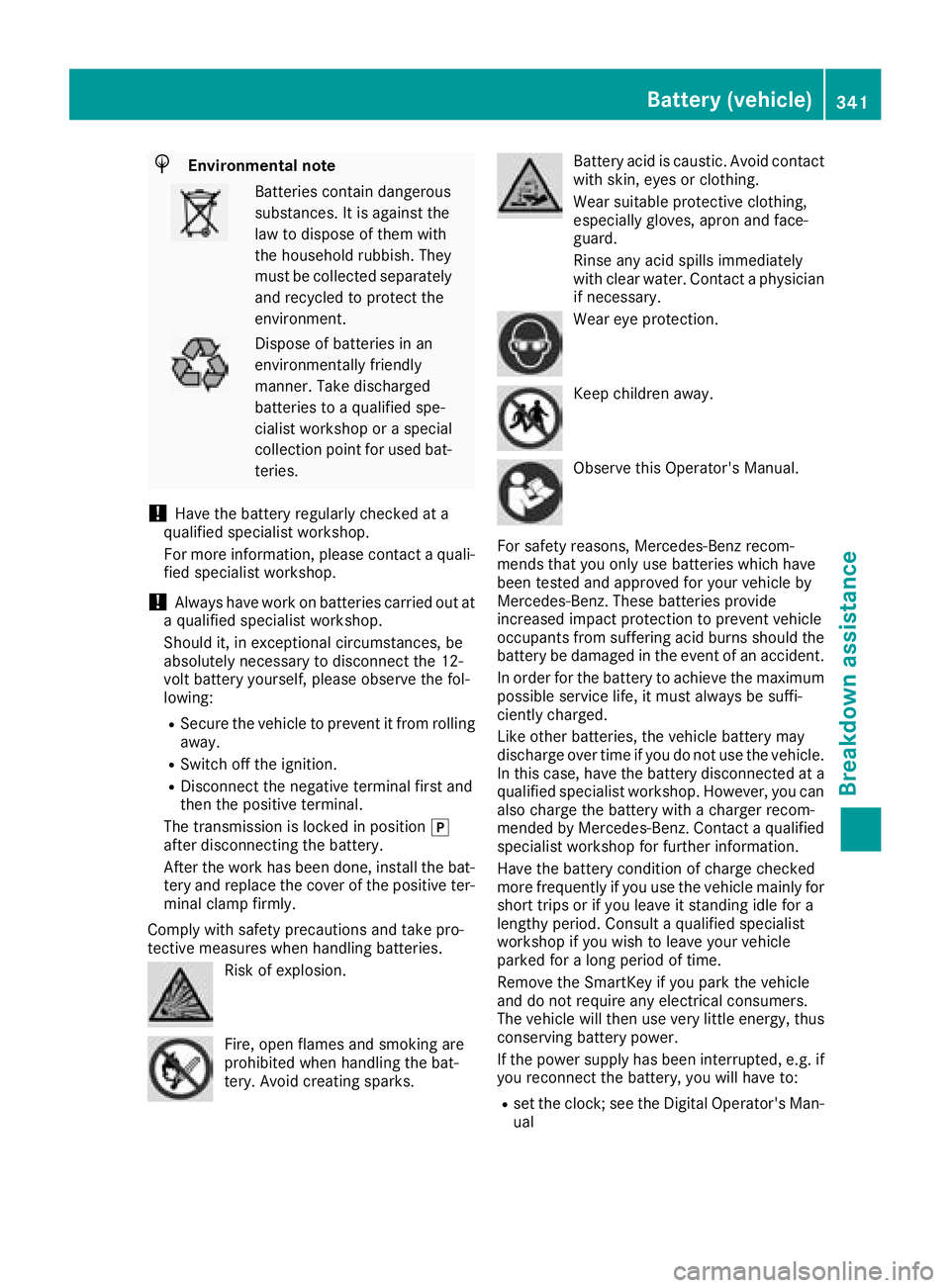
HEnvironmental note
Batteries contain dangerous
substances. It is against the
law to dispose of them with
the household rubbish. They
must be collected separatelyand recycled to protect the
environment.
Dispose of batteries in an
environmentally friendly
manner. Take discharged
batteries to a qualified spe-
cialist workshop or a special
collection point for used bat-
teries.
!Have the battery regularly checked at a
qualified specialist workshop.
For more information, please contact a quali-
fied specialist workshop.
!Always have work on batteries carried out at
a qualified specialist workshop.
Should it, in exceptional circumstances, be
absolutely necessary to disconnect the 12-
volt battery yourself, please observe the fol-
lowing:
RSecure the vehicle to prevent it from rolling
away.
RSwitch off the ignition.
RDisconnect the negative terminal first and
then the positive terminal.
The transmission is locked in position j
after disconnecting the battery.
After the work has been done, install the bat-
tery and replace the cover of the positive ter-
minal clamp firmly.
Comply with safety precautions and take pro-
tective measures when handling batteries.
Risk of explosion.
Fire, open flames and smoking are
prohibited when handling the bat-
tery. Avoid creating sparks.
Battery acid is caustic. Avoid contact
with skin, eyes or clothing.
Wear suitable protective clothing,
especially gloves, apron and face-
guard.
Rinse any acid spills immediately
with clear water. Contact a physician
if necessary.
Wear eye protection.
Keep children away.
Observe this Operator's Manual.
For safety reasons, Mercedes-Benz recom-
mends that you only use batteries which have
been tested and approved for your vehicle by
Mercedes-Benz. These batteries provide
increased impact protection to prevent vehicle
occupants from suffering acid burns should the
battery be damaged in the event of an accident.
In order for the battery to achieve the maximum
possible service life, it must always be suffi-
ciently charged.
Like other batteries, the vehicle battery may
discharge over time if you do not use the vehicle.
In this case, have the battery disconnected at a
qualified specialist workshop. However, you can also charge the battery with a charger recom-
mended by Mercedes-Benz. Contact a qualified
specialist workshop for further information.
Have the battery condition of charge checked
more frequently if you use the vehicle mainly for
short trips or if you leave it standing idle for a
lengthy period. Consult a qualified specialist
workshop if you wish to leave your vehicle
parked for a long period of time.
Remove the SmartKey if you park the vehicle
and do not require any electrical consumers.
The vehicle will then use very little energy, thusconserving battery power.
If the power supply has been interrupted, e.g. if
you reconnect the battery, you will have to:
Rset the clock; see the Digital Operator's Man-
ual
Battery (vehicle)341
Breakdown assistance
Z
Page 346 of 398
Make sure that:
RThe jumper cables are not damaged.
RBare parts of the terminal clamp do not come into contact with other metal parts while the jumpercables are connected to the battery.
RThe jumper cables cannot come into contact with parts which can move when the engine is
running, such as the V-belt pulley or the fan.
XSecure the vehicle by applying the electric parking brake.
XShift the transmission to position j.
XMake sure that the ignition is switched off. All indicator lamps in the instrument cluster must be
off. When using the SmartKey, turn the SmartKey to position uin the ignition lock and remove it
(
Ypage 135).
XSwitch off all electrical consumers, e.g. rear window defroster, lighting, etc.
XOpen the hood.
iRight-hand-drive vehicle: the jump-starting connection points may be located on the other
side of the vehicle.
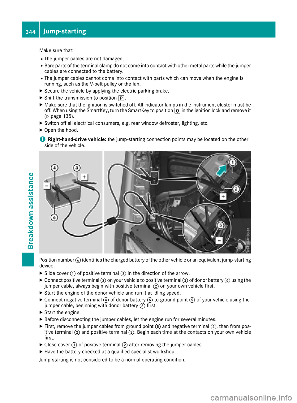
Position number Bidentifies the charged battery of the other vehicle or an equivalent jump-starting
device.
XSlide cover :of positive terminal ;in the direction of the arrow.
XConnect positive terminal ;on your vehicle to positive terminal =of donor battery Busing the
jumper cable, always begin with positive terminal ;on your own vehicle first.
XStart the engine of the donor vehicle and run it at idling speed.
XConnect negative terminal ?of donor battery Bto ground point Aof your vehicle using the
jumper cable, beginning with donor battery Bfirst.
XStart the engine.
XBefore disconnecting the jumper cables, let the engine run for several minutes.
XFirst, remove the jumper cables from ground point Aand negative terminal ?, then from pos-
itive terminal ;and positive terminal =. Begin each time at the contacts on your own vehicle
first.
XClose cover :of positive terminal ;after removing the jumper cables.
XHave the battery checked at a qualified specialist workshop.
Jump-starting is not considered to be a normal operating condition.
344Jump-starting
Breakdown assistance
Page 348 of 398
driver's or front-passenger door, which could
damage the transmission.
!Do not tow with sling-type equipment. This
could damage the vehicle.
!Vehicles with differential locks: make sure
the differential locks are in automatic mode.
When towing, the differential locks must not
be switched on. The transmission may other-
wise be damaged.
!The vehicle can be towed a maximum of
30 miles (50km). The towing speed of 30 mph (50 km/h) must not be exceeded.
If the vehicle has to be towed more than
30 miles (50km), the entire vehicle must be
raised and transported.
It is better to have the vehicle transported than
to have it towed away.
If the vehicle has suffered transmission damage,
have it transported on a transporter or trailer.
The automatic transmission must be in position
i when the vehicle is being towed.
The battery must be connected and charged.
Otherwise, you:
Rcannot turn the SmartKey to position 2in
the ignition lock
Rcannot release the electric parking brake
Rcannot shift the automatic transmission to
position i
Disarm the automatic locking feature before the vehicle is towed (
Ypage 239). You could other-
wise be locked out when pushing or towing the
vehicle.
If the vehicle is in a dangerous area, it can be
towed out of that area with both axles on the
ground. In this case, the towing distance must
not be greater than 165 ft (50 m)and must not
exceed a towing speed of 6 mph (10 km/h). For
longer distances, have the vehicle loaded and
transported.
Installing/removing the towing eye
Installing the towing eye
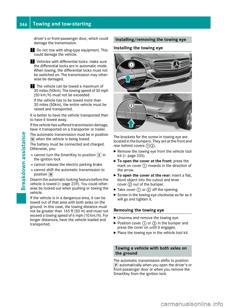
The brackets for the screw-in towing eye are
located in the bumpers. They are at the front and
rear behind covers :;.
XRemove the towing eye from the vehicle tool
kit (Ypage 335).
XTo open the cover at the front: press the
mark on cover :inwards in the direction of
the arrow.
XTo open the cover at the rear: insert a flat,
blunt object into the cutout and lever
cover ;out of the bumper.
XTake cover :or; off the opening.
XScrew in the towing eye clockwise as far as it
will go and tighten it.
Removing the towing eye
XUnscrew and remove the towing eye.
XPosition cover :or; in the bumper and
press the cover on until it engages.
XPlace the towing eye in the vehicle tool kit.
Towing a vehicle with both axles on
the ground
The automatic transmission shifts to position
j automatically when you open the driver's or
front-passenger door or when you remove the
SmartKey from the ignition lock.
346Towing and tow-starting
Breakdown assistance
Page 351 of 398

XRemove theSmartKey from th eignition lock.
Or, on vehicles wit hKEYLESS-GO start function
or KEYLESS‑ GO:
XOpen thedriver' sdoor .
The vehicl eelectronics are no win ke yposi-
tion u.This is th esam eas th eSmartKey
having been removed.
The driver’s door can be closed again .
XSecureth evehicl eagainst rollin gaway
(Ypage 156).
All indicator lamp sin th einstrumen tcluste r
mus tbe off .
The fuses are locate din various fus eboxes:
RFus ebox on th efront-passenger side of th e
dashboar d
RFusebox in th eengin ecompartmen ton th e
right-hand side of th evehicle, when viewed in
th edirection of travel
RFus ebox under th erear bench seat
Dashboard fuse box
!
Do no tuse apointe dobjec tsuc has ascrew-
driver to open th ecover in th edashboard. You
could damag eth edashboar dor th ecover .
Mercedes-Ben zrecommends that you hav ethis
wor kperformed at aqualified specialist work-
shop, e.g. at an authorize dMercedes-Ben zCen -
ter.
XOpen th efront-passenger door .
XTo open:pull cover :outwards in th edirec-
tion of th earrow and remove it .
XTo close:clipin cover :on th efron tof th e
dashboard.
XFold cover :inwards until it engages.
Fuse box in the engine compartment
GWARNIN G
When th ehoo dis open and th ewindshield
wiper sare set in motion ,you can be injured by
th ewiper linkage. There is aris kof injury.
Always switch off th ewindshield wiper sand
th eignition before opening th ehood.
XOpen th ehoo d (Ypage 321).
XUse adry cloth to remove any moisture from
th efus ebox .
XTo open :open clamps ;.
XFold up cover :in th edirection of th earrow
and remove it .
XTo close:checkwhether th eseal is seated
correctl yin cover :.
XInsertcover :at th eside of th efus ebox int o
th eretainers .
XFold down cover :and close clamps ;.
XClose thehood.
Fuses349
Breakdown assistance
Z
Page 360 of 398
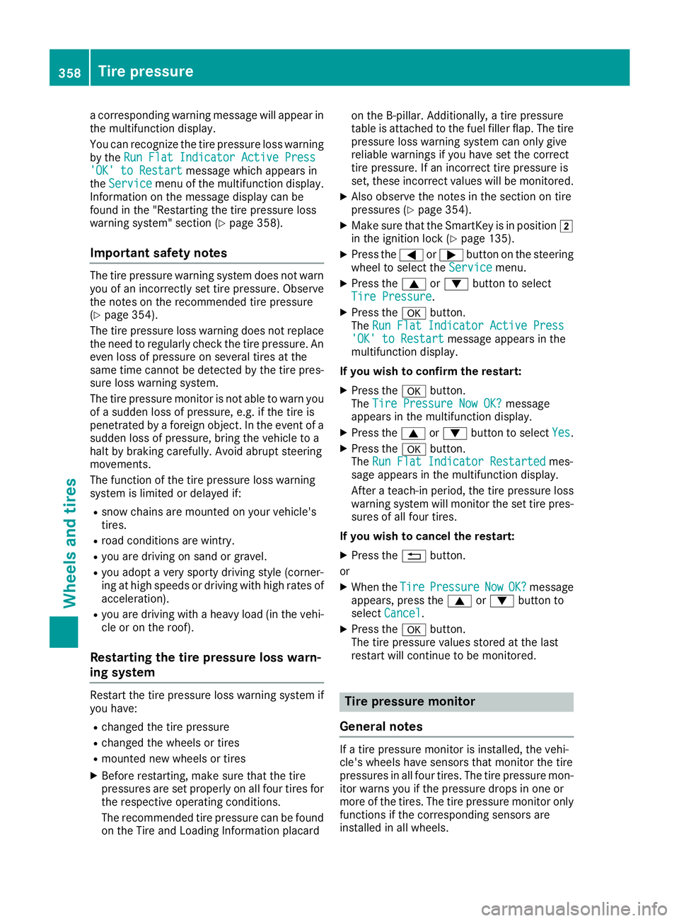
a corresponding warning message will appear in
the multifunction display.
You can recognize the tire pressure loss warning
by theRun Flat Indicator Active Press
'OK' to Restartmessage which appears in
the Servicemenu of the multifunction display.
Information on the message display can be
found in the "Restarting the tire pressure loss
warning system" section (
Ypage 358).
Important safety notes
The tire pressure warning system does not warn you of an incorrectly set tire pressure. Observe
the notes on the recommended tire pressure
(
Ypage 354).
The tire pressure loss warning does not replace
the need to regularly check the tire pressure. An
even loss of pressure on several tires at the
same time cannot be detected by the tire pres-
sure loss warning system.
The tire pressure monitor is not able to warn you
of a sudden loss of pressure, e.g. if the tire is
penetrated by a foreign object. In the event of a
sudden loss of pressure, bring the vehicle to a
halt by braking carefully. Avoid abrupt steering
movements.
The function of the tire pressure loss warning
system is limited or delayed if:
Rsnow chains are mounted on your vehicle's
tires.
Rroad conditions are wintry.
Ryou are driving on sand or gravel.
Ryou adopt a very sporty driving style (corner-
ing at high speeds or driving with high rates of acceleration).
Ryou are driving with a heavy load (in the vehi-
cle or on the roof).
Restarting the tire pressure loss warn-
ing system
Restart the tire pressure loss warning system ifyou have:
Rchanged the tire pressure
Rchanged the wheels or tires
Rmounted new wheels or tires
XBefore restarting, make sure that the tire
pressures are set properly on all four tires for
the respective operating conditions.
The recommended tire pressure can be found on the Tire and Loading Information placard on the B-pillar. Additionally, a tire pressure
table is attached to the fuel filler flap. The tire
pressure loss warning system can only give
reliable warnings if you have set the correct
tire pressure. If an incorrect tire pressure is
set, these incorrect values will be monitored.
XAlso observe the notes in the section on tire
pressures (Ypage 354).
XMake sure that the SmartKey is in position
2
in the ignition lock (Ypage 135).
XPress the =or; button on the steering
wheel to select the Servicemenu.
XPress the9or: button to select
Tire Pressure.
XPress the abutton.
The Run Flat Indicator Active Press
'OK' to Restartmessage appears in the
multifunction display.
If you wish to confirm the restart:
XPress the abutton.
The Tire Pressure Now OK?message
appears in the multifunction display.
XPress the 9or: button to select Yes.
XPress theabutton.
The Run Flat Indicator Restartedmes-
sage appears in the multifunction display.
After a teach-in period, the tire pressure loss
warning system will monitor the set tire pres-
sures of all four tires.
If you wish to cancel the restart:
XPress the %button.
or
XWhen the TirePressureNowOK?message
appears, press the 9or: button to
select Cancel
.
XPress the abutton.
The tire pressure values stored at the last
restart will continue to be monitored.
Tire pressure monitor
General notes
If a tire pressure monitor is installed, the vehi-
cle's wheels have sensors that monitor the tire
pressures in all four tires. The tire pressure mon-
itor warns you if the pressure drops in one or
more of the tires. The tire pressure monitor only
functions if the corresponding sensors are
installed in all wheels.
358Tire pressure
Wheels and tires
Page 362 of 398
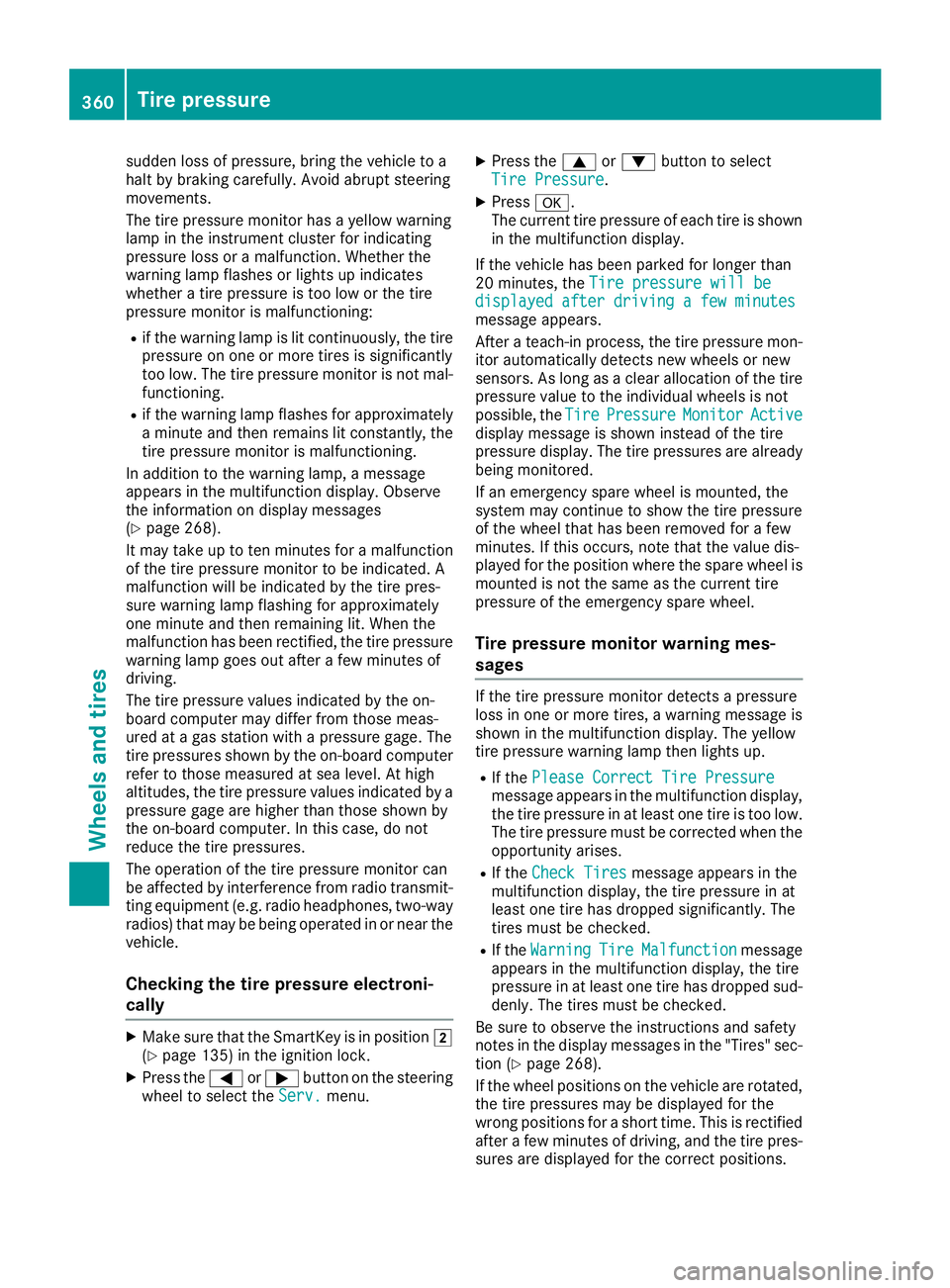
sudden loss of pressure, bring the vehicle to a
halt by braking carefully. Avoid abrupt steering
movements.
The tire pressure monitor has a yellow warning
lamp in the instrument cluster for indicating
pressure loss or a malfunction. Whether the
warning lamp flashes or lights up indicates
whether a tire pressure is too low or the tire
pressure monitor is malfunctioning:
Rif the warning lamp is lit continuously, the tire
pressure on one or more tires is significantly
too low. The tire pressure monitor is not mal-functioning.
Rif the warning lamp flashes for approximately
a minute and then remains lit constantly, the
tire pressure monitor is malfunctioning.
In addition to the warning lamp, a message
appears in the multifunction display. Observe
the information on display messages
(
Ypage 268).
It may take up to ten minutes for a malfunction
of the tire pressure monitor to be indicated. A
malfunction will be indicated by the tire pres-
sure warning lamp flashing for approximately
one minute and then remaining lit. When the
malfunction has been rectified, the tire pressure
warning lamp goes out after a few minutes of
driving.
The tire pressure values indicated by the on-
board computer may differ from those meas-
ured at a gas station with a pressure gage. The
tire pressures shown by the on-board computer
refer to those measured at sea level. At high
altitudes, the tire pressure values indicated by a pressure gage are higher than those shown by
the on-board computer. In this case, do not
reduce the tire pressures.
The operation of the tire pressure monitor can
be affected by interference from radio transmit-
ting equipment (e.g. radio headphones, two-way
radios) that may be being operated in or near the vehicle.
Checking the tire pressure electroni-
cally
XMake sure that the SmartKey is in position 2
(Ypage 135) in the ignition lock.
XPress the =or; button on the steering
wheel to select the Serv.menu.
XPress the9or: button to select
Tire Pressure.
XPress a.
The current tire pressure of each tire is shown
in the multifunction display.
If the vehicle has been parked for longer than
20 minutes, the Tire pressure will be
displayed after driving a few minutesmessage appears.
After a teach-in process, the tire pressure mon-
itor automatically detects new wheels or new
sensors. As long as a clear allocation of the tire
pressure value to the individual wheels is not
possible, theTire
PressureMonitorActivedisplay message is shown instead of the tire
pressure display. The tire pressures are already
being monitored.
If an emergency spare wheel is mounted, the
system may continue to show the tire pressure
of the wheel that has been removed for a few
minutes. If this occurs, note that the value dis-
played for the position where the spare wheel is
mounted is not the same as the current tire
pressure of the emergency spare wheel.
Tire pressure monitor warning mes-
sages
If the tire pressure monitor detects a pressure
loss in one or more tires, a warning message is
shown in the multifunction display. The yellow
tire pressure warning lamp then lights up.
RIf thePlease Correct Tire Pressuremessage appears in the multifunction display,
the tire pressure in at least one tire is too low.
The tire pressure must be corrected when the
opportunity arises.
RIf theCheck Tiresmessage appears in the
multifunction display, the tire pressure in at
least one tire has dropped significantly. The
tires must be checked.
RIf the WarningTireMalfunctionmessage
appears in the multifunction display, the tire
pressure in at least one tire has dropped sud-
denly. The tires must be checked.
Be sure to observe the instructions and safety
notes in the display messages in the "Tires" sec-
tion (
Ypage 268).
If the wheel positions on the vehicle are rotated, the tire pressures may be displayed for the
wrong positions for a short time. This is rectified
after a few minutes of driving, and the tire pres-
sures are displayed for the correct positions.
360Tire pressure
Wheels and tires
Page 363 of 398
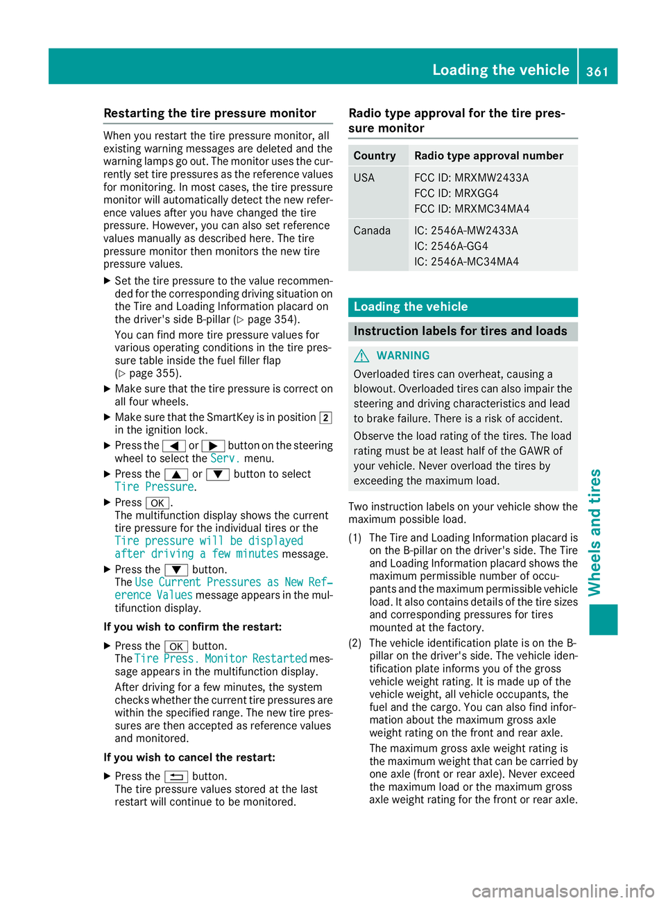
Restarting the tire pressure monitor
When you restart the tire pressure monitor, all
existing warning messages are deleted and the
warning lamps go out. The monitor uses the cur-
rently set tire pressures as the reference values
for monitoring. In most cases, the tire pressure
monitor will automatically detect the new refer-
ence values after you have changed the tire
pressure. However, you can also set reference
values manually as described here. The tire
pressure monitor then monitors the new tire
pressure values.
XSet the tire pressure to the value recommen-
ded for the corresponding driving situation on
the Tire and Loading Information placard on
the driver's side B-pillar (
Ypage 354).
You can find more tire pressure values for
various operating conditions in the tire pres-
sure table inside the fuel filler flap
(
Ypage 355).
XMake sure that the tire pressure is correct on
all four wheels.
XMake sure that the SmartKey is in position 2
in the ignition lock.
XPress the =or; button on the steering
wheel to select the Serv.menu.
XPress the9or: button to select
Tire Pressure.
XPress a.
The multifunction display shows the current
tire pressure for the individual tires or the
Tire pressure will be displayed
after driving a few minutesmessage.
XPress the :button.
The UseCurrentPressuresasNewRef‐erenceValuesmessage appears in the mul-
tifunction display.
If you wish to confirm the restart:
XPress the abutton.
The TirePress.MonitorRestartedmes-
sage appears in the multifunction display.
After driving for a few minutes, the system
checks whether the current tire pressures are
within the specified range. The new tire pres-
sures are then accepted as reference values
and monitored.
If you wish to cancel the restart:
XPress the %button.
The tire pressure values stored at the last
restart will continue to be monitored.
Radio type approval for the tire pres-
sure monitor
CountryRadio type approval number
USAFCC ID: MRXMW2433A
FCC ID: MRXGG4
FCC ID: MRXMC34MA4
CanadaIC: 2546A-MW2433A
IC: 2546A-GG4
IC: 2546A-MC34MA4
Loading the vehicle
Instruction labels for tires and loads
GWARNING
Overloaded tires can overheat, causing a
blowout. Overloaded tires can also impair the steering and driving characteristics and lead
to brake failure. There is a risk of accident.
Observe the load rating of the tires. The load
rating must be at least half of the GAWR of
your vehicle. Never overload the tires by
exceeding the maximum load.
Two instruction labels on your vehicle show the maximum possible load.
(1) The Tire and Loading Information placard is on the B-pillar on the driver's side. The Tire
and Loading Information placard shows the
maximum permissible number of occu-
pants and the maximum permissible vehicle
load. It also contains details of the tire sizes
and corresponding pressures for tires
mounted at the factory.
(2) The vehicle identification plate is on the B- pillar on the driver's side. The vehicle iden-
tification plate informs you of the gross
vehicle weight rating. It is made up of the
vehicle weight, all vehicle occupants, the
fuel and the cargo. You can also find infor-
mation about the maximum gross axle
weight rating on the front and rear axle.
The maximum gross axle weight rating is
the maximum weight that can be carried by
one axle (front or rear axle). Never exceed
the maximum load or the maxi mum g
ross
axle weight rating for the front or rear axle.
Loading the vehicle361
Wheels and tires
Z