2018 MERCEDES-BENZ GLC wheel
[x] Cancel search: wheelPage 363 of 390
able cargo and luggage load capacity is
650 lbs (1400 - 750 (5 x 150) = 650 lbs). X
Step 5: Determine the combined weight of
luggage and cargo being loaded on the vehi- cle. That weight may not safely exceed the
available cargo and luggage load capacity cal-
culated in step 4.
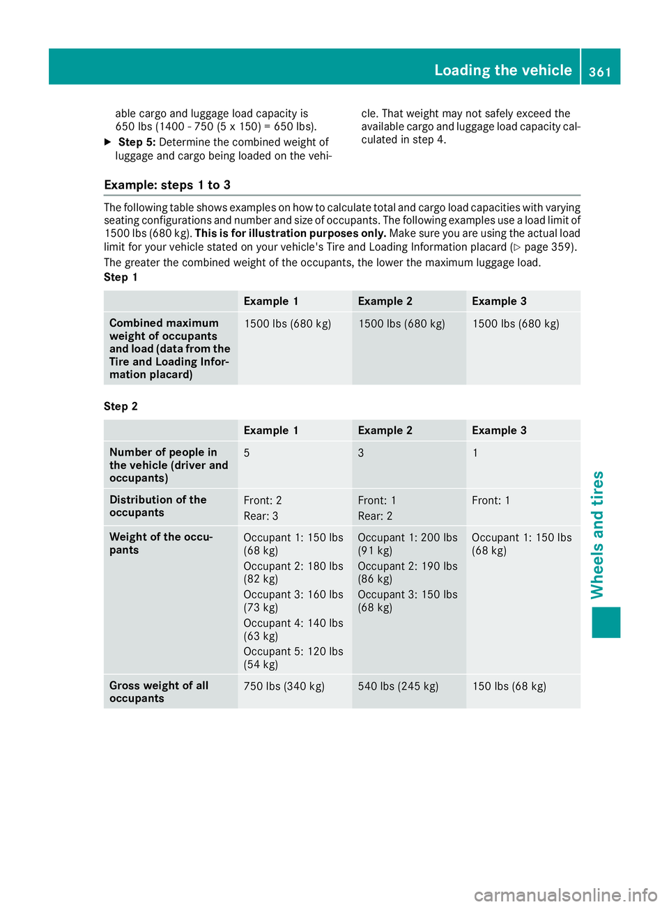
Example: steps 1 to 3 The following table shows examples on how to calculate total and cargo load capacities with varying
seating configurations and number and size of occupants. The following examples use a load limit of
1500 lbs (680 kg). This is for illustration purposes only. Make sure you are using the actual load
limit for your vehicle stated on your vehicle's Tire and Loading Information placard ( Y
page 359).
The greater the combined weight of the occupants, the lower the maximum luggage load.
Step 1
Example 1 Example 2 Example 3
Combined maximum
weight of occupants
and load (data from the
Tire and Loading Infor-
mation placard) 1500 lbs (680 kg) 1500 lbs (680 kg) 1500 lbs (680 kg)
Step 2
Example 1 Example 2 Example 3
Number of people in
the vehicle (driver and
occupants) 5 3 1
Distribution of the
occupants Front: 2
Rear: 3 Front: 1
Rear: 2 Front: 1
Weight of the occu-
pants Occupant 1: 150 lbs
(68 kg)
Occupant 2: 180 lbs
(82 kg)
Occupant 3: 160 lbs
(73 kg)
Occupant 4: 140 lbs
(63 kg)
Occupant 5: 120 lbs
(54 kg) Occupant 1: 200 lbs
(91 kg)
Occupant 2: 190 lbs
(86 kg)
Occupant 3: 150 lbs
(68 kg) Occupant 1: 150 lbs
(68 kg)
Gross weight of all
occupants 750 lbs (340 kg) 540 lbs (245 kg) 150 lbs (68 kg)Loading the vehicle 361
Wheels and tires Z
Page 365 of 390
i The actual values for tires are vehicle-spe-
cific and may deviate from the values in the
illustration.
Treadwear The treadwear grade is a comparative rating
based on the wear rate of the tire when tested
under controlled conditions on a specified U.S.
government course. For example, a tire graded
150 would wear one and one-half times as well
on the government course as a tire graded 100.
The relative performance of tires depends upon
the actual conditions of their use, however, and
may depart significantly from the norm due to
variations in driving habits, service practices
and differences in road characteristics and cli-
mate.
Traction
G WARNING
The traction grade assigned to this tire is
based on straight-ahead braking traction
tests, and does not include acceleration, cor-
nering, hydroplaning, or peak traction char-
acteristics.
! Avoid wheelspin. This can lead to damage to
the drive train.
The traction grades – from highest to lowest –
are AA, A, B and C. Those grades represent the
tire's ability to stop on wet pavement as meas-
ured under controlled conditions on specified
government test surfaces of asphalt and con-
crete. A tire marked C may have poor traction
performance.
The safe speed on a wet, snow covered or icy
road is always lower than on dry road surfaces.
You should pay special attention to road condi-
tions when temperatures are around freezing
point.
Mercedes-Benz recommends a minimum tread
depth of �
Page 370 of 390
Speed rating The speed rating is part of the tire identification.
It specifies the speed range for which the tire is
approved.
GVW (Gross Vehicle Weight) The gross vehicle weight includes the weight of
the vehicle including fuel, tools, the spare wheel,
accessories installed, occupants, luggage and
the drawbar noseweight, if applicable. The gross
vehicle weight must not exceed the gross vehi-
cle weight rating GVWR as specified on the vehi-
cle identification plate on the B-pillar on the
driver's side.
GVWR (Gross Vehicle Weight Rating) The GVWR is the maximum permissible gross
weight of a fully loaded vehicle (the weight of the
vehicle including all accessories, occupants,
fuel, luggage and the drawbar noseweight, if
applicable). The gross vehicle weight rating is
specified on the vehicle identification plate on
the B-pillar on the driver's side.
Maximum loaded vehicle weight The maximum weight is the sum of: R
the curb weight of the vehicle R
the weight of the accessories R
the load limit R
the weight of the factory installed optional
equipment
Kilopascal (kPa) Metric unit for tire pressure. 6.9 kPa corre-
sponds to 1 psi. Another unit for tire pressure is
bar. 100 kilopascals (kPa) are the equivalent of
1 bar.
Load index
In addition to the load-bearing index, the load
index may also be imprinted on the sidewall of
the tire. This specifies the load-bearing capacity
more precisely.
Curb weight
The weight of a vehicle with standard equipment
including the maximum capacity of fuel, oil and
coolant. It also includes the air-conditioning sys-
tem and optional equipment if these are instal-
led in the vehicle, but does not include passen-
gers or luggage. Maximum load rating The maximum tire load is the maximum permis-
sible weight in kilograms or lbs for which a tire is
approved.
Maximum permissible tire pressure Maximum permissible tire pressure for one tire.
Maximum load on one tire Maximum load on one tire. This is calculated by
dividing the maximum axle load of one axle by
two.
PSI (pounds per square inch) A standard unit of measure for tire pressure.
Aspect ratio Relationship between tire height and tire width
in percent.
Tire pressure This is pressure inside the tire applying an out-
ward force to each square inch of the tire's sur-
face. The tire pressure is specified in pounds per
square inch (psi), in kilopascal (kPa) or in bar.
The tire pressure should only be corrected when
the tires are cold.
Cold tire pressure The tires are cold: R
if the vehicle has been parked with the tires
out of direct sunlight for at least three hours
and R
if the vehicle has not been driven further than
1 mile (1.6 km)
Tread
The part of the tire that comes into contact with
the road.
Bead
The tire bead ensures that the tire sits securely
on the wheel. There are several steel wires in the
bead to prevent the tire from coming loose from
the wheel rim.
Sidewall
The part of the tire between the tread and the
bead.368
All about wheels and tires
Wheels and tires
Page 372 of 390
the tires are installed corresponding to the
direction of rotation.
An arrow on the sidewall of the tire indicates its
correct direction of rotation.
Storing wheels Store wheels that are not being used in a cool,
dry and preferably dark place. Protect the tires
from oil, grease, gasoline and diesel.
Mounting a wheel
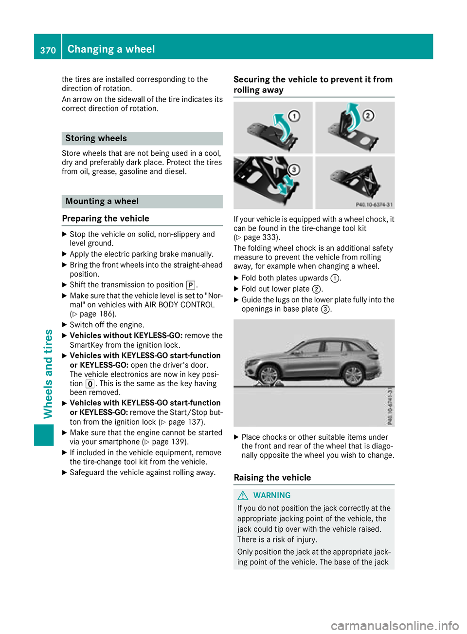
Preparing the vehicle X
Stop the vehicle on solid, non-slippery and
level ground. X
Apply the electric parking brake manually. X
Bring the front wheels into the straight-ahead
position. X
Shift the transmission to position �] .X
Make sure that the vehicle level is set to "Nor-
mal" on vehicles with AIR BODY CONTROL
( Y
page 186).X
Switch off the engine. X
Vehicles without KEYLESS-GO: remove the
SmartKey from the ignition lock. X
Vehicles with KEYLESS-GO start-function
or KEYLESS-GO: open the driver's door.
The vehicle electronics are now in key posi-
tion �
Page 373 of 390

must be positioned vertically, directly under
the jacking point of the vehicle.
! Only position the jack at the appropriate
jacking point of the vehicle. Otherwise, you
could damage the vehicle.
Observe the following when raising the vehi-
cle: R
To raise the vehicle, only use the vehicle-spe-
cific jack that has been tested and approved
by Mercedes-Benz. If used incorrectly, the
jack could tip over with the vehicle raised. R
The jack is designed only to raise and hold the
vehicle for a short time while a wheel is being
changed. It must not be used for performing
maintenance work under the vehicle. R
Avoid changing the wheel on uphill and down-
hill slopes. R
Before raising the vehicle, secure it from roll-
ing away by applying the parking brake and
inserting wheel chocks. Do not disengage the
parking brake while the vehicle is raised. R
The jack must be placed on a firm, flat and
non-slip surface. On a loose surface, a large,
flat, load-bearing underlay must be used. On a
slippery surface, a non-slip underlay must be
used, e.g. rubber mats. R
Do not use wooden blocks or similar objects
as a jack underlay. Otherwise, the jack will not
be able to achieve its load-bearing capacity
due to the restricted height. R
Make sure that the distance between the
underside of the tires and the ground does not
exceed 1.2 in (3 cm). R
Do not place your hands or feet under the
raised vehicle. R
Do not lie under the vehicle. R
Do not start the engine when the vehicle is
raised. R
Never open or close a door or the tailgate
when the vehicle is raised. R
Make sure that no persons are present in the
vehicle when the vehicle is raised. X
Using lug wrench �C , loosen the bolts on the
wheel you wish to change by about one full
turn. Do not unscrew the bolts completely.
The jacking points are located just behind the
front wheel housings and just in front of the rear
wheel housings (arrows). X
Take the ratchet wrench out of the tire-chang-
ing tool kit and place it on the hexagon nut of
the jack so that the letters AUF are visible.
X
Position jack �
Page 375 of 390

Lowering the vehicle
G WARNING
The wheels could work loose if the wheel nuts
and bolts are not tightened to the specified
tightening torque. There is a risk of accident.
Have the tightening torque immediately
checked at a qualified specialist workshop
after a wheel is changed. X
Place the ratchet wrench onto the hexagon
nut of the jack so that the letters AB are visi-
ble. X
Turn the ratchet wrench until the vehicle is
once again standing firmly on the ground. X
Place the jack to one side.
X
Tighten the wheel bolts evenly in a crosswise
pattern in the sequence indicated ( �C to �
Page 376 of 390
Observe the notes on recommended tire pres-
sures under various operating conditions
( Y
page 352).
Check tire pressures regularly, and only when
the tires are cold. Comply with the maintenance
recommendations of the tire manufacturer in
the vehicle document wallet.
Notes on the vehicle equipment – always equip
the vehicle: R
with tires of the same size on a given axle (left
and right) R
with the same type of tires at a given time
(summer tires, winter tires, MOExtended
tires)
Exception: it is permissible to install a differ-
ent type or make in the event of a flat tire.
Observe the "MOExtended tires (tires with
run-flat characteristics" section ( Y
page 334).
Vehicles equipped with MOExtended tires are
not equipped with a TIREFIT kit at the factory. It
is therefore recommended that you additionally
equip your vehicle with a TIREFIT kit if you mount
tires that do not feature run-flat properties, e.g.
winter tires. A TIREFIT kit may be obtained from
a qualified specialist workshop.374
Wheel/tire combination
Wheels and tires
Page 385 of 390
Missing values were not available at time of
going to print.
Mercedes-AMG
GLC 43 4MATIC
Vehicle length
183.5 in (4661 mm)
Vehicle width
including exterior
mirrors 82.5 in (2096 mm)
Vehicle height
64.1 in (1627 mm)
Wheelbase
113.1 in (2873 mm)
Turning radius
39.7 ft (12.10 m)
Maximum roof load
165 lb (75 kg)
Mercedes-AMG
GLC 63 4MATIC+
Vehicle length
184.2 in (4679 mm)
Vehicle width
including exterior
mirrors 82.5 in (2096 mm)
Vehicle height
63.8 in (1620 mm)
Wheelbase
113.1 in (2873 mm)
Turning radius
39.7 ft (12.10 m)
Maximum roof load
165 lb (75 kg)
Mercedes-AMG
GLC 63 S 4MATIC+
Vehicle length
184.3 in (4682 mm)
Vehicle width
including exterior
mirrors 82.5 in (2096 mm)
Vehicle height
64.0 in (1625 mm)
Wheelbase
113.1 in (2873 mm)
Turning radius
39.7 ft (12.10 m)
Maximum roof load
165 lb (75 kg) All other models
Vehicle length
183.3 in (4656 mm)
Vehicle width
including exterior
mirrors 82.5 in (2096 mm)
Vehicle height
65.5 in (1664 mm)
Wheelbase
113.1 in (2873 mm)
Turning radius
38.7 ft (11.80 m)
Maximum roof load
165 lb (75 kg)
Vehicle data for off-road driving
Maximum water depth
! The water depth must not exceed the speci-
fied value. Note that the permissible water
depth is less in flowing water.
Maximum water depth �C when the vehicle is
ready to drive can be found in the following
table.
When the vehicle is loaded and ready to drive, it
has a full tank, all fluids have been refilled and
the driver is in the vehicle.
Further information about driving on flooded
roads ( Y
page 165).Vehicle data for off-road driving 383
Technical data Z