2018 MERCEDES-BENZ G-CLASS dimensions
[x] Cancel search: dimensionsPage 22 of 294
Transmissionsee Automatic transmission
Transmission positions .................... 114
Transporting the vehicle .................. 253
Traveling uphill
Brow of hill ..................................... 132
Trim pieces (cleaning instruc-
tions) .................................................. 241
Trip computer (on-board com-
puter) .................................................. 163
Trip odometer
Calling up ....................................... 163
Resetting (on-board computer) ...... 163
Turn signals
Display message ............................ 180
Replacing bulbs (front) ..................... 91
Switching on/off .............................. 88
TV
Operating (on-board computer) ..... 166
see Separate operating instructions
Two-way radio
Frequencies ................................... 281
Installation ..................................... 281
Transmission output (maximum) .... 281
TWR (Tongue Weight Rating) (defi-
nition) ................................................. 275
Type identification plate
see Vehicle identification plate
U
UnlockingEmergency unlocking ....................... 68
From inside the vehicle (central
unlocking button) ............................. 67
USB devices
Connecting to the Media Inter-
face ...............................................2 08
V
Vanity mirror
Sun visor ........................................ 216
Vehicle
Correct use ...................................... 27
Data acquisition ............................... 28
Display message ............................ 190
Equipment ....................................... 24 Individual settings .......................... 168
Limited Warranty .............................2
8
Loading .......................................... 266
Locking (in an emergency) ............... 68
Locking (SmartKey) .......................... 63
Lowering ........................................ 278
Maintenance .................................... 25
Operation outside the USA/
Canada ............................................ 25
Parking .......................................... 122
Parking for a long period ................ 124
Pulling away ................................... 106
Raising ........................................... 276
Securing from rolling away ............ 276
Tow-starting ................................... 254
Towing ........................................... 251
Transporting .................................. 253
Unlocking (in an emergency) ........... 68
Unlocking (SmartKey) ...................... 63
Vehicle data ................................... 288
Vehicle data ....................................... 288
Vehicle data (off-road driving)
Approach/departure angle ............ 290
Fording depth ................................ 290
Maximum gradient climbing abil-
ity .................................................. 290
Vehicle dimensions ........................... 288
Vehicle emergency locking ................ 68
Vehicle identification number
see VIN
Vehicle identification plate .............. 282
Vehicle tool kit .................................. 244
Ventilation
Setting the airflow ........................... 99
Video
Operating the DVD ......................... 166
see also Digital Operator's Man-
ual .................................................. 203
VIN
Type plate ...................................... 282
W
Warning and indicator lampsABS ................................................ 194
Brakes ........................................... 193
Check Engine ................................. 199
Coolant .......................................... 199
20Index
Page 159 of 294
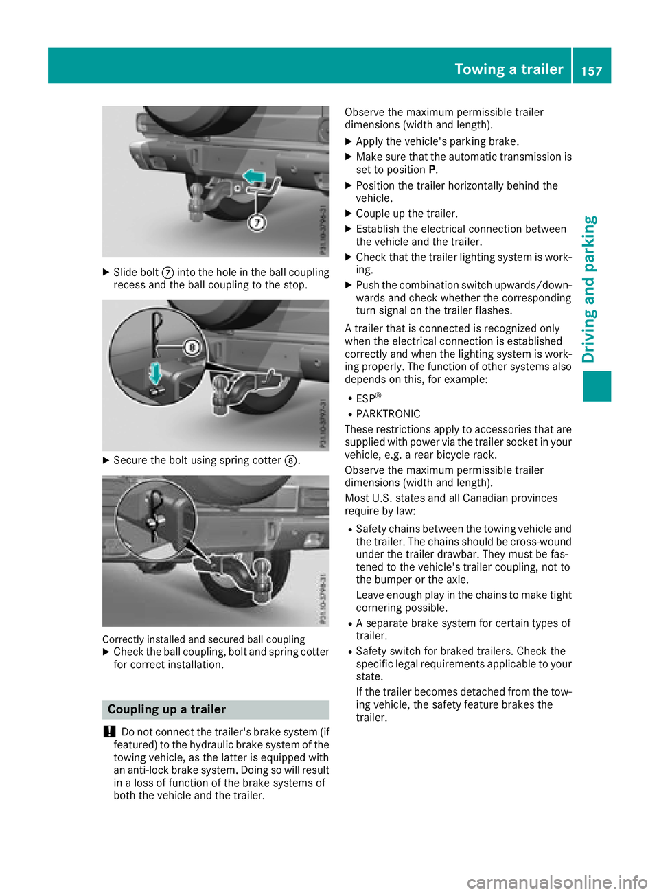
XSlide boltCinto the hole in the ball coupling
recess and the ball coupling to the stop.
XSecure the bolt using spring cotter D.
Correctly installed and secured ball couplingXCheck the ball coupling, bolt and spring cotter
for correct installation.
Coupling up a trailer
!
Do not connect the trailer's brake system (if
featured) to the hydraulic brake system of the
towing vehicle, as the latter is equipped with
an anti-lock brake system. Doing so will result
in a loss of function of the brake systems of
both the vehicle and the trailer. Observe the maximum permissible trailer
dimensions (width and length).
XApply the vehicle's parking brake.
XMake sure that the automatic transmission is
set to position
P.
XPosition the trailer horizontally behind the
vehicle.
XCouple up the trailer.
XEstablish the electrical connection between
the vehicle and the trailer.
XCheck that the trailer lighting system is work-
ing.
XPush the combination switch upwards/down-
wards and check whether the corresponding
turn signal on the trailer flashes.
A trailer that is connected is recognized only
when the electrical connection is established
correctly and when the lighting system is work-
ing properly. The function of other systems also
depends on this, for example:
RESP®
RPARKTRONIC
These restrictions apply to accessories that are
supplied with power via the trailer socket in your
vehicle, e.g. a rear bicycle rack.
Observe the maximum permissible trailer
dimensions (width and length).
Most U.S. states and all Canadian provinces
require by law
:
RSafety chains between the towing vehicle and
the trailer. The chains should be cross-wound
under the trailer drawbar. They must be fas-
tened to the vehicle's trailer coupling, not to
the bumper or the axle.
Leave enough play in the chains to make tight
cornering possible.
RA separate brake system for certain types of
trailer.
RSafety switch for braked trailers. Check the
specific legal requirements applicable to your
state.
If the trailer becomes detached from the tow-
ing vehicle, the safety feature brakes the
trailer.
Towing a trailer157
Driving and parking
Z
Page 261 of 294
Drivingwit hsummer tire s
At temperature sbelo w45 ‡(+7 †), elasticity in
summer tires is significantly lower and thus also
traction and braking power. Change the tires on
your vehicle to M+S tires. Using summer tires at
very cold temperatures could cause cracks to
form, thereby damaging the tires permanently.
Mercedes-Benz cannot accept responsibility for
this type of damage.
GWARNING
Damaged tires can cause tire inflation pres-
sure loss. As a result, you could lose control of
your vehicle. There is a risk of accident.
Check the tires regularly for signs of damage
and replace any damaged tires immediately.
M+S tires
GWARNING
M+S tires with a tire tread depth of less than
ã in (4 mm) are not suitable for use in winter
and do not provide sufficient traction. There is
a risk of an accident.
M+S tires with a tread depth of less than ãin
(4 mm) must be replaced immediately.
GWARNING
Wheel and tire dimensions as well as the type of tire can vary between the spare wheel and
the wheel to be replaced. When the spare
wheel is mounted, driving characteristics may be severely affected. There is a risk of an acci-
dent.
In order to reduce risks:
Ryou should therefore adapt your driving
style and drive carefully.
Rnever mount more than one spare wheel
that differs from the wheel to be replaced.
Ronly use a spare wheel that differs from the
wheel to be replaced for a short time.
Rdo not deactivate ESP®.
Rhave a spare wheel that differs from the
wheel that has been changed replaced at
the nearest qualified specialist workshop.
You must observe the correct wheel and
tire dimensions as well as the wheel type.
Do not exceed a maximum speed of 50 mph
(80 km/h) if a spare wheel of a different size is
installed.
At temperatures below 45 ‡(+7 †), use winter
tires or all-season tires. Both types of tire are
identified by the M+S marking.
Only winter tires bearing the isnowflake
symbol in addition to the M+S marking provide
the best possible grip in wintry road conditions.
Only these tires will allow driving safety systems
such as ABS and ESP
®to function optimally in
winter. These tires have been developed specif-
ically for driving in snow.
Use M+S tires of the same make and tread on all
wheels to maintain safe handling characteris-
tics.
Always observe the maximum permissible
speed specified for the M+S tires you have
mounted.
When you have mounted the M+S tires:
XCheck the tire pressures (Ypage 263).
XRestart the tire pressure monitor
(Ypage 265).
Snow chains
GWARNING
If you drive too fast with snow chains moun-
ted, they may snap. As a result, you could
injure others and damage the vehicle. There is
a risk of an accident.
Observe the maximum permissible speed for
operation with snow chains.
!Information about the use of snow chain
compatible AMG winter tires is applicable for
AMG tires. Use of snow chains is only per-
missible with these tires.
!On some tire sizes there is not enough space
for snow chains. To avoid damage to the vehi- cle or tires, observe the "Wheel and tire com-
binations" section under "Tires and wheels".
Winter operation259
Wheels and tires
Z
Page 277 of 294
PSI (pounds per square inch)
A standard unit of measure for tire pressure.
Aspect ratio
Relationship between tire height and tire width
in percent.
Tire pressure
This is pressure inside the tire applying an out-
ward force to each square inch of the tire's sur-
face. The tire pressure is specified in pounds per
square inch (psi), in kilopascals (kPa) or in bar.
The tire pressure should only be corrected when
the tires are cold.
Cold tire pressure
The tires are cold:
Rif the vehicle has been parked with the tires
out of direct sunlight for at least three hours
and
Rif the vehicle has not been driven further than
1 mile (1.6 km)
Tread
The part of the tire that comes into contact with
the road.
Bead
The tire bead ensures that the tire sits securely
on the wheel. There are several steel wires in the
bead to prevent the tire from coming loose fromthe wheel rim.
Sidewall
The part of the tire between the tread and the
bead.
Weight of optional extras
The combined weight of those optional extras
that weigh more than the replaced standard
parts and more than 2.3 kg (5 lbs). These
optional extras, such as high-performance
brakes, level control, a roof rack or a high-per-
formance battery, are not included in the curb
weight and the weight of the accessories.
TIN (Tire Identification Number)
This is a unique identifier which can be used by
a tire manufacturer to identify tires, for example
for a product recall, and thus identify the pur-
chasers. The TIN is made up of the manufactur-
er's identity code, tire size, tire type code and
the manufacturing date.
Load bearing index
The load bearing index (also load index) is a code
that contains the maximum load bearing capa-
city of a tire.
Traction
Traction is the result of friction between the tires
and the road surface.
TWR (Tongue Weight Rating)
The TWR specifies the maximum permissible
weight that the ball coupling of the trailer tow
hitch can support.
Treadwear indicators
Narrow bars (tread wear bars) that are distrib-
uted over the tire tread. If the tire tread is level
with the bars, the wear limit of áin (1.6 mm)
has been reached.
Occupant distribution
The distribution of occupants in a vehicle at their
designated seating positions.
Total load limit
Nominal load and luggage load plus 68 kg
(150 lbs) multiplied by the number of seats in
the vehicle.
Changing a wheel
Flat tire
You can find information on what to do in the
event of a flat tire in the "Breakdown assistance"
section (
Ypage 246).
Rotating the wheels
GWARNING
Interchanging the front and rear wheels may
severely impair the driving characteristics if
the wheels or tires have different dimensions. The wheel brakes or suspension components
may also be damaged. There is a risk of acci-
dent.
Rotate front and rear wheels only if the wheels and tires are of the same dimensions.
Changing a wheel275
Wheels and tires
Z
Page 281 of 294
The tightening torque must be96 lb-ft
(130 Nm).
XDismantle the pump lever.
XPush the jack piston back in and close the
drain plug.
XUse the nuts to secure the faulty wheel to the
spare wheel bracket (Ypage 245).
XStow the jack and the vehicle tools in the
vehicle again.
XCheck the tire pressure of the newly installed
wheel and adjust it if necessary.
Observe the recommended tire pressure
(
Ypage 260).
If you are driving with the emergency spare
wheel installed, the tire pressure monitor can-
not function reliably. Only restart the tire pres-
sure monitor when the defective wheel has been replaced with a new wheel.
All mounted wheels must be equipped with func-
tioning sensors for the tire pressure monitor.
Wheel and tire combinations
You can ask for information regarding permittedwheel/tire combinations at an authorized
Mercedes-Benz Center.
!For safety reasons, Mercedes-Benz recom-
mends that you only use tires, wheels and
accessories which have been specifically
approved by Mercedes-Benz for your vehicle.
These are specially adapted to the various
driving safety systems, such as ABS or ESP
®.
Only use tires, wheels and accessories tested
and recommended by Mercedes-Benz. Cer-
tain characteristics, such as handling, vehicle
noise emissions, fuel consumption, etc. may
otherwise be adversely affected. In addition,
other wheel sizes may cause the tires to rub
against the vehicle body and axle compo-
nents, when under load. This may result in
damage to the tire or to the vehicle.
Mercedes-Benz is not responsible for any
damage caused by using tires, wheels or
accessories different from those recommen-
ded.
Information on tires, wheels and permissible
combinations can be obtained at a qualified
specialist workshop.
!Retreaded tires are neither tested nor rec-
ommended by Mercedes-Benz, since previ- ous damage cannot always be detected on
retreaded tires. As a result, Mercedes-Benz
cannot guarantee vehicle safety if retreaded
tires are mounted. Do not mount used tires if
you have no information about their previous
usage.
The recommended pressures for various oper-
ating conditions can be found:
Ron the Tire and Loading Information placard
on the B-pillar on the driver's side
Rin the tire pressure table in the fuel filler flap
Observe the notes on recommended tire pres-
sures under various operating conditions
(
Ypage 260).
Check tire pressures regularly, and only when
the tires are cold. Comply with the maintenance
recommendations of the tire manufacturer in
the vehicle document wallet.
Notes on equipping the vehicle:
Ralways install tires of the same size on one
axle (left/right)
Ralways install the same type of tires on your
vehicle (summer tires, winter tires, all-
weather tires, all-terrain tires)
Spare wheel
If the tire and wheel dimensions of the spare
wheel differ from the wheel to be replaced, the
spare wheel is an emergency spare wheel.
GWARNING
Wheel and tire dimensions as well as the type of tire can vary between the spare wheel and
the wheel to be replaced. When the spare
wheel is mounted, driving characteristics may be severely affected. There is a risk of an acci-
dent.
In order to reduce risks:
Ryou should therefore adapt your driving
style and drive carefully.
Rnever mount more than one spare wheel
that differs from the wheel to be replaced.
Ronly use a spare wheel that differs from the
wheel to be replaced for a short time.
Spare wheel279
Wheels and tires
Z
Page 282 of 294
Rdo not deactivate ESP®.
Rhave a spare wheel that differs from the
wheel that has been changed replaced at
the nearest qualified specialist workshop.
You must observe the correct wheel and
tire dimensions as well as the wheel type.
!Only use the emergency spare wheel or
spare wheel of a different size briefly, and only
to drive to the nearest qualified specialist
workshop. You could otherwise damage the
drive train.
When using an emergency spare wheel or spare
wheel of a different size, you must not exceed
the maximum permissible speed of 50 mph
(80 km/h).
Snow chains must not be installed on emer-
gency spare wheels or to a spare wheel of a dif-
ferent size.
You may install the spare wheel against the
direction of rotation.
If a spare wheel is installed, the tire pressure
monitor may continue to show the tire pressure
of the wheel that has been removed for a few
minutes. The value displayed for the position
where the emergency spare wheel is installed is
not the same as the current tire pressure of the
spare wheel.
You should regularly check the pressure of all
your tires, including the spare wheel, particu-
larly prior to long trips, and correct the pressure
as necessary (
Ypage 260).
Remove the spare wheel from the spare wheel
bracket (
Ypage 245).
You can ask for information regarding permitted spare wheels at an authorized Mercedes-Benz
Center.
280Spare wheel
Wheels and tires
Page 290 of 294

Refrigerant instruction label
Example: refrigerant instruction label
:Warning symbol
;Refrigerant filling capacity
=Applicable standards
?PAG oil part number
AType of refrigerant
Warning symbol :advises you about:
RPossible dangers
RHaving service work carried out at a qualified
specialist workshop
Filling capacities
Missing values were not available at time of
going to print.
ModelRefrigerant
Mercedes-AMG vehicles
G 550
ModelPAG oil
Mercedes-AMG vehicles
G 550
Vehicle data
General notes
Please note that for the specified vehicle data:
RThe heights specified may vary as a result of:
-Tires
-Load
-Condition of the suspension
-Optional equipment
RThe vehicle length specified includes the front
license plate adapter.
Dimensions and weights
Missing values were not available at time of
going to print.
G 550
: Distance to top
edge75 in - 78.9 in
(1905 mm -2005 mm)
; Distance to lower
edge26.8 in - 30.7 in
(680 mm -780 mm)
= Range of movement36.7 in (931 mm)
288Vehicle data
Technical data
Page 293 of 294

which corresponds to an approach/departure
angle of 45°.
Accelerate carefully and make sure that the
wheels do not spin when driving on steep ter-
rain.
iIf the load on the front axle is reduced when
pulling away on a steep uphill slope, the front
wheels have a tendency to spin. 4ETS detects
this and brakes the wheels accordingly. The
rear wheel torque is increased, making it eas-
ier to drive off.
For further information about the maximum gra-
dient climbing ability, see (
Ypage 132).
Trailer tow hitch
Permissible trailer load, braked (at a
minimum gradient-climbing capabil-
ity of 12% from a standstill)
Missing values were not available at time of
going to print.
Model
Mercedes-AMG
G 65
All other models7716 lbs (3500 kg)
Maximum drawbar noseweight
!
Use a drawbar noseweight as close as pos-
sible to the maximum permissible nose-
weight. Do not use a noseweight of less than
50 kg, otherwise the trailer may come loose.
Note that the payload and the rear axle load
are reduced by the actual payload.
The drawbar load reduces the permissible over-
all load and rear axle load.
The drawbar load acts from above onto the ball
head on the trailer tow hitch.
The drawbar noseweight is not included in the
trailer load. Missing values were not available at time of
going to print.
ModelPermissible nose-
weight
Mercedes-AMG
G 65
All other models308.6 lbs (140kg )
The actual noseweight may not be higher than
the value which is given. The value can be found
on the trailer tow hitch or trailer identification
plates. The lowest weight applies.
The maximum permissible trailer drawbar nose-
weight is the maximum weight with which the
trailer drawbar can be loaded. The permissible
trailer drawbar noseweight is the limit for
Mercedes-Benz-approved trailer couplings.
Ball position
Ball position of the ball coupling
When choosing a ball coupling, the dimensions
stated in the illustration must not be exceeded.
Gross rear axle weight rating when
towing a trailer
Missing values were not available at time of
going to print.
ModelGross axle weight rating
Mercedes-AMG
G 65
All other models4189 lbs (1900 kg)
Trailer tow hitch291
Technical data
Z