Page 255 of 294

XWhen the vehicle is stationary, depress the
brake pedal and keep it depressed.
XShift the transfer case to positionNeutral
(Ypage 150).
XShift the automatic transmission to position
i.
XLeave the SmartKey in position 2in the igni-
tion lock.
XRelease the brake pedal.
XRelease the parking brake.
XSwitch on the hazard warning lamps
(Ypage 88).
In order to signal a change of direction when
towing the vehicle with the hazard warning
lamps switched on, use the combination switch
as usual. In this case, only the indicator lamps
for the direction of travel flash. After resetting
the combination switch, the hazard warning
lamp starts flashing again.
iThe automatic transmission can only
change gear when the battery has sufficient
charge.
If you cannot shift the automatic transmission
to position i, the propeller shafts to the
driven axles must be removed.
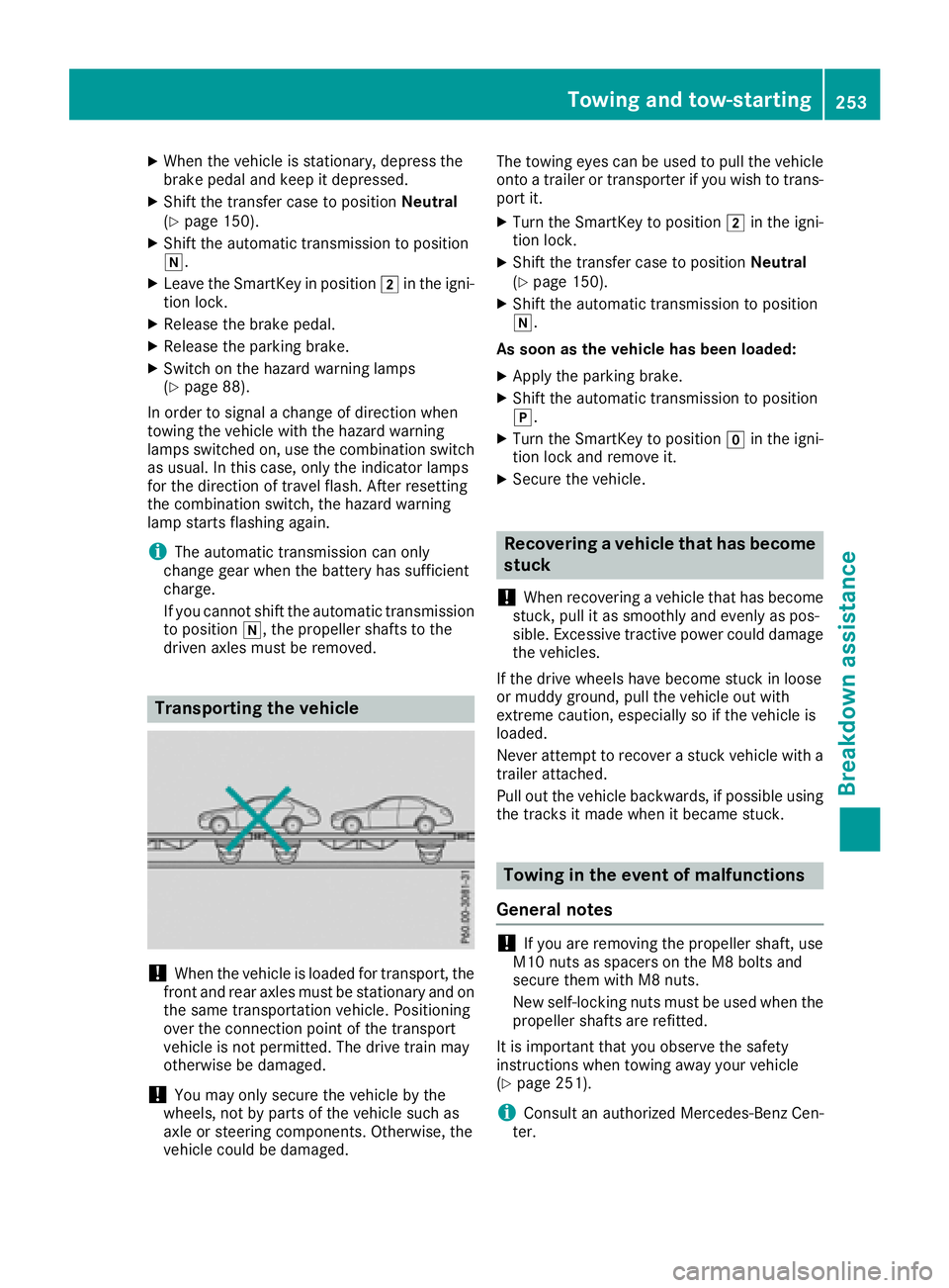
Transporting the vehicle
!When the vehicle is loaded for transport, the
front and rear axles must be stationary and on the same transportation vehicle. Positioning
over the connection point of the transport
vehicle is not permitted. The drive train may
otherwise be damaged.
!You may only secure the vehicle by the
wheels, not by parts of the vehicle such as
axle or steering components. Otherwise, the
vehicle could be damaged. The towing eyes can be used to pull the vehicle
onto a trailer or transporter if you wish to trans-
port it.
XTurn the SmartKey to position 2in the igni-
tion lock.
XShift the transfer case to position Neutral
(Ypage 150).
XShift the automatic transmission to position
i.
As soon as the vehicle has been loaded:
XApply the parking brake.
XShift the automatic transmission to position
j.
XTurn the SmartKey to position gin the igni-
tion lock and remove it.
XSecure the vehicle.
Recovering a vehicle that has become
stuck
!
When recovering a vehicle that has become
stuck, pull it as smoothly and evenly as pos-
sible. Excessive tractive power could damage
the vehicles.
If the drive wheels have become stuck in loose
or muddy ground, pull the vehicle out with
extreme caution, especially so if the vehicle is
loaded.
Never attempt to recover a stuck vehicle with a
trailer attached.
Pull out the vehicle backwards, if possible using the tracks it made when it became stuck.
Towing in the event of malfunctions
General notes
!If you are removing the propeller shaft, use
M10 nuts as spacers on the M8 bolts and
secure them with M8 nuts.
New self-locking nuts must be used when the
propeller shafts are refitted.
It is important that you observe the safety
instructions when towing away your vehicle
(
Ypage 251).
iConsult an authorized Mercedes-Benz Cen-
ter.
Towing and tow-starting253
Breakdown assistance
Z
Page 269 of 294

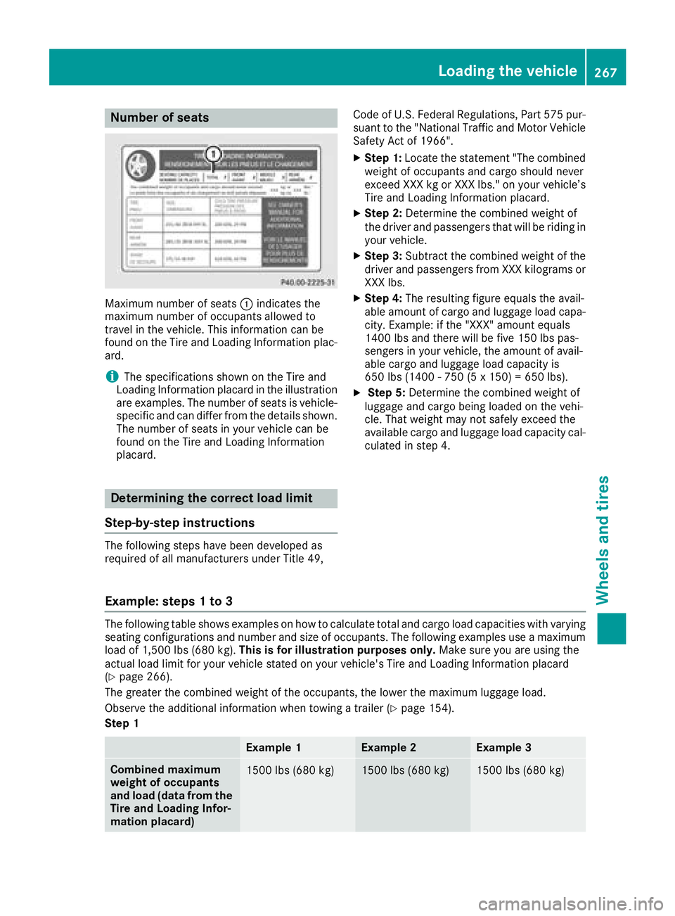
Number of seats
Maximum number of seats:indicates the
maximum number of occupants allowed to
travel in the vehicle. This information can be
found on the Tire and Loading Information plac-
ard.
iThe specifications shown on the Tire and
Loading Information placard in the illustration
are examples. The number of seats is vehicle-
specific and can differ from the details shown.
The number of seats in your vehicle can be
found on the Tire and Loading Information
placard.
Determining the correct load limit
Step-by-step instructions
The following steps have been developed as
required of all manufacturers under Title 49, Code of U.S. Federal Regulations, Part 575 pur-
suant to the "National Traffic and Motor Vehicle
Safety Act of 1966".
XStep 1: Locate the statement "The combined
weight of occupants and cargo should never
exceed XXX kg or XXX lbs." on your vehicle’s
Tire and Loading Information placard.
XStep 2: Determine the combined weight of
the driver and passengers that will be riding in your vehicle.
XStep 3: Subtract the combined weight of the
driver and passengers from XXX kilograms or
XXX lbs.
XStep 4: The resulting figure equals the avail-
able amount of cargo and luggage load capa-
city. Example: if the "XXX" amount equals
1400 lbs and there will be five 150 lbs pas-
sengers in your vehicle, the amount of avail-
able cargo and luggage load capacity is
650 lbs (1400 - 750 (5 x 150) = 650 lbs).
XStep 5: Determine the combined weight of
luggage and cargo being loaded on the vehi-
cle. That weight may not safely exceed the
available cargo and luggage load capacity cal- culated in step 4.
Example: steps 1 to 3
The following table shows examples on how to calculate total and cargo load capacities with varying
seating configurations and number and size of occupants. The following examples use a maximum
load of 1,500 lbs (680 kg). This is for illustration purposes only. Make sure you are using the
actual load limit for your vehicle stated on your vehicle's Tire and Loading Information placard
(
Ypage 266).
The greater the combined weight of the occupants, the lower the maximum luggage load.
Observe the additional information when towing a trailer (
Ypage 154).
Step 1
Example 1Example 2Example 3
Combined maximum
weight of occupants
and load (data from the
Tire and Loading Infor-
mation placard)1500 lbs (680 kg)1500 lbs (680 kg)1500 lbs (680 kg)
Loading the vehicle267
Wheels and tires
Z
Page 293 of 294

which corresponds to an approach/departure
angle of 45°.
Accelerate carefully and make sure that the
wheels do not spin when driving on steep ter-
rain.
iIf the load on the front axle is reduced when
pulling away on a steep uphill slope, the front
wheels have a tendency to spin. 4ETS detects
this and brakes the wheels accordingly. The
rear wheel torque is increased, making it eas-
ier to drive off.
For further information about the maximum gra-
dient climbing ability, see (
Ypage 132).
Trailer tow hitch
Permissible trailer load, braked (at a
minimum gradient-climbing capabil-
ity of 12% from a standstill)
Missing values were not available at time of
going to print.
Model
Mercedes-AMG
G 65
All other models7716 lbs (3500 kg)
Maximum drawbar noseweight
!
Use a drawbar noseweight as close as pos-
sible to the maximum permissible nose-
weight. Do not use a noseweight of less than
50 kg, otherwise the trailer may come loose.
Note that the payload and the rear axle load
are reduced by the actual payload.
The drawbar load reduces the permissible over-
all load and rear axle load.
The drawbar load acts from above onto the ball
head on the trailer tow hitch.
The drawbar noseweight is not included in the
trailer load. Missing values were not available at time of
going to print.
ModelPermissible nose-
weight
Mercedes-AMG
G 65
All other models308.6 lbs (140kg )
The actual noseweight may not be higher than
the value which is given. The value can be found
on the trailer tow hitch or trailer identification
plates. The lowest weight applies.
The maximum permissible trailer drawbar nose-
weight is the maximum weight with which the
trailer drawbar can be loaded. The permissible
trailer drawbar noseweight is the limit for
Mercedes-Benz-approved trailer couplings.
Ball position
Ball position of the ball coupling
When choosing a ball coupling, the dimensions
stated in the illustration must not be exceeded.
Gross rear axle weight rating when
towing a trailer
Missing values were not available at time of
going to print.
ModelGross axle weight rating
Mercedes-AMG
G 65
All other models4189 lbs (1900 kg)
Trailer tow hitch291
Technical data
Z