Page 357 of 506

RThevehicle has been loaded onto
th e transpor ter cor rectly
RThe vehicle is secured at all four
wheels with suit abletensioning
st ra ps
RThe maximum permissible speed of
35 mph (60 km/h) is not exceeded
when transporting
* NO
TEDama getotheve hicle from secur‐
ing it incor rectly
#Af ter loading, theve hicle must be
secured at all four wheels. Otherwise,
th eve hicle could be damaged.
#A minimum dis tance of 8 in (20 cm) up
and 4 in (10 cm) down must bekept to
th e transport platform.
#Secure theve hicle on all four wheels af ter
loading. 4MATIC
vehicles/ve hicles with automatic
transmission
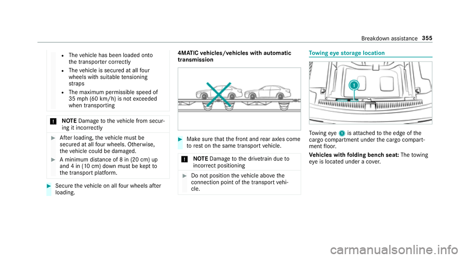
#Make sure that the front and rear axles come
to rest on the same transport vehicle.
* NO
TEDama getothe driv etra in due to
incor rect positioning
#Do not position theve hicle abo vethe
connection point of the transport vehi‐
cle.
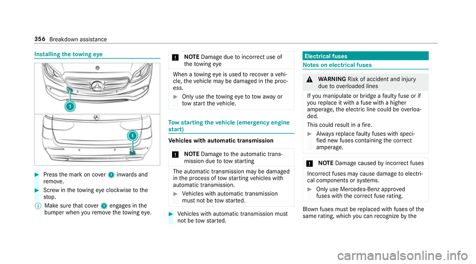
To wing eyesto rage location
Towing eye1 is attached tothe edge of the
cargo compart ment underthe cargo compart‐
ment floor.
Ve hicles with folding bench seat: Thetowing
ey e is located under a co ver.
Breakdown assis tance 355
Page 358 of 506

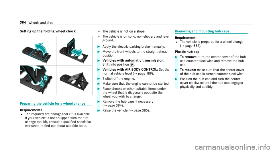
Installingtheto wing eye
#Press the mark on co ver1 inwa rds and
re mo ve.
#Scr ew intheto wing eyeclockwise tothe
st op.
% Make sure that co ver1 engages in the
bumper when youre mo vetheto wing eye. *
NO
TEDama gedue toincor rect use of
th eto wing eye
When a towing eye is used toreco ver a vehi‐
cle, theve hicle may be damaged in the proc‐
ess.
#Only use theto wing eyeto to waw ay or
to w start theve hicle.
To w starting theve hicle (eme rgency engine
st art)
Ve hicles with automatic transmission
* NO
TEDama getothe automatic trans‐
mission due to towstarting
The automatic transmission may be damaged
in the process of tow starting vehicles with
automatic transmission.
#Ve hicles with automatic transmission
must not be tow star ted.
#Ve hicles with automatic transmission must
not be tow star ted.
Electrical fuses
Note s on electrical fuses
&
WARNING Risk of accident and injury
due to ov erloaded lines
If yo u manipulate or bridge a faulty fuse or if
yo ure place it with a fuse with a higher
amperage, the electric line could be overloa‐
ded.
This could result in a fire .
#Alw aysre place faulty fuses with speci‐
fi ed new fuses conta iningthe cor rect
amperage.
* NO
TEDama gecaused byincor rect fuses
Incor rect fuses may cause damage toelectri‐
cal components or sy stems.
#Only use Mercedes-Benz appr oved
fuses with the cor rect fuse rating.
Blown fuses must bereplaced with fuses of the
same rating, which you can recognize bythe
356
Breakdown assis tance
Page 386 of 506

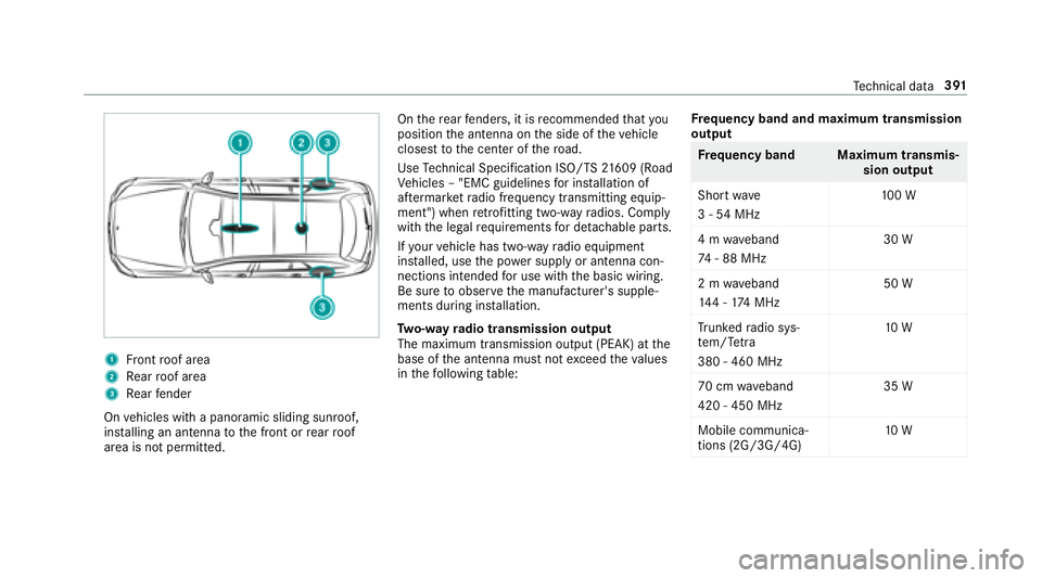
Setting upthefo lding wheel chock
Prepa ring theve hicle for a wheel change
Re quirementsRThe requ ired tire-change tool kit is available.
If yo ur vehicle is not equipped with the tire-
ch ange tool kit, consult a qualified specialist
wo rkshop tofind out about suitable tools.
RThe vehicle is not on a slope.
RThe vehicle is on solid, non-slippery and le vel
ground .
#Applythe electric parking brake manually.
#Mo vethe front wheels tothest ra ight-ahead
position.
#Ve hicles with automatic transmission:
Shift into position j.
#Vehicles with AIR BODY CONT ROL:Set the
normal vehicle le vel (→page 189).
#Switch off the engine.
#Make sure that the engine cannot bestar ted.
#Place choc ks orother suitable items under
th e wheel that is diagonally opposite the
wheel you wish tochange.
#Re mo vethe hub caps if necessary
(→page 384).
#Ra ise theve hicle (→page 385).
Re moving and mounting hub caps
Requirement:RThe vehicle is prepared for a wheel change
(→page 384).
Plast ic hub cap
#Toremo ve:turn the center co ver of the hub
cap counter-clockwise and remo vethe hub
cap.
#To mount: makesurethat the center co ver
of the hub cap is turned counter-clockwise.
#Po sition the hub cap and turn the center
co ver clockwise until the hub cap engages
ph ysically and audibly.
384
Wheels and tires
Page 393 of 506

1Front roof area
2Re ar roof area
3Re ar fender
On vehicles with a panoramic sliding sunroof,
ins talling an antenna tothe front or rear roof
area is not permitted. On
there ar fende rs, it is recommended that you
position the antenna on the side of theve hicle
closest tothe center of thero ad.
Use Tech nical Specification ISO/TS 21609 (Road
Ve hicles – "EMC guidelines for ins tallation of
af te rm arke tra dio frequency transmitting equip‐
ment") when retrofitting two-w ayradios. Comply
with the legal requ irements for de tachable parts.
If yo ur vehicle has two-w ayradio equipment
ins talled, use the po wer supply or antenna con‐
nections intended for use with the basic wiring.
Be sure toobser vethe manufacturer's supple‐
ments during ins tallation.
Tw o-w ayradio transmission output
The maximum transmission output (PEAK) at the
base of the antenna must not exceed theva lues
in thefo llowing table: Fr
equency band and maximum transmission
output
Fr equency band Maximum transmis‐
sion output
Sho rtwa ve
3 - 54 MHz 10
0 W
4 m waveband
74 - 88 MHz 30 W
2 m waveband
14 4 - 174 MHz 50 W
Tr unked radio sys‐
te m/T etra
380 - 460 MHz 10
W
70 cm waveband
420 - 450 MHz 35 W
Mobile communica‐
tions (2G/3G/4G) 10
W
Tech nical da ta391
Page 394 of 506
Thefollowing can be used in theve hicle without
re strictions:
RTw o-w ayradios with a maximum transmis‐
sion output of up to100 mW
RTw o-w ayradios with transmit ter frequencies
in the 380 - 410 MHz frequency band and a
maximum transmission output of up to2 W
(trunked radio sy stem/T etra )
RMobile phones (2G/3G/4G)
There are no restrictions when positioning the
antenna on the outside of theve hicle forth efo l‐
lowing frequency bands:
RTr unked radio sy stem/T etra
R70 cm waveband
R2G/3G/4G
Vehicle identification plate, VIN and engine
number
Ve hicle identification plate
Vehicle identification plate (USA only)
1
Pe rm issible grossmass
2Pe rm issible front axle load
3Perm issible rear axle load
4Pa int code
5VIN (vehicle identification number)
392
Tech nical da ta
Page 442 of 506

Displaymessages
Possible causes/consequences and MSolutions
Â
�3�O�D�F�H �W�K�H �.�H�\ �L�Q �W�K�H
�0�D�U�N�H�G �6�S�D�F�H �6�H�H �2�S�H�U�D��
�W�R�U�
�V �0�D�Q�X�D�O*T
he SmartK eydetection function is malfunctioning.
#Change the location of the SmartK eyintheve hicle.
#Start theve hicle with the SmartK eyinthestow age compartment .
Vehicle
Display messages
Possible causes/consequences and MSolutions
�$�S�S�O�\ �%�U�D�N�H �W�R �6�K�L�I�W �I�U�R�P
�
�3�
*
Yo u ha veattem ptedto shift the transmission out of position jand into ano ther transmission position.
#Depress the brake pedal.
�7�R �'�H�V�H�O�H�F�W �3 �R�U �1��
�'�H�S�U�H�V�V �%�U�D�N�H �D�Q�G �6�W�D�U�W
�(�Q�J�L�Q�H *
Yo u ha veattem ptedto shift the transmission out of position jori into ano ther transmission position.
#Depress the brake pedal.
#St art the engine.
�'�U�L�Y�H�U�
�V �'�R�R�U �2�S�H�Q �
�7�U�D�Q�V�P�L�V�V�L�R�Q �1�R�W �L�Q �3 �5�L�V�N
�R�I �9�H�K�L�F�O�H �5�R�O�O�L�Q�J �$�Z�D�\ *
The driver's door is not fully closed and the transmission is in position k,iorh.
#Shift the transmission toposition jwhen you park theve hicle.
44 0
Displ aymessage s andwarning/indicator lamps
Page 443 of 506

Displaymessages
Possible causes/consequences and MSolutions
�1 �3�H�U�P�D�Q�H�Q�W�O�\ �$�F�W�L�Y�H �5�L�V�N
�R�I �5�R�O�O�L�Q�J �$�Z�D�\ *
While theve hicle is rolling or while you are driving, the transmission has been shif tedto position i.
#Depress the brake pedal tostop and, when theve hicle is stationar y,shift the transmission toposition j.
#Tocontinue your journe y,shift the transmission toposition hork.
�2�Q�O�\ �6�K�L�I�W �W�R �
�3�
�Z�K�H�Q �9�H�K�L��
�F�O�H �L�V �6�W�D�W�L�R�Q�D�U�\ *
The transmission can only be shif tedto position jwhen theve hicle is stationar y.
�6�H�U�Y�L�F�H �5�H�T�X�L�U�H�G �'�R �1�R�W
�6�K�L�I�W �*�H�D�U�V �9�L�V�L�W �'�H�D�O�H�U *T
he transmission is malfunctioning. The transmission position can no longer be shif ted.
#When the transmission is in position h, consult aqualified specialist workshop and do not change the trans‐
mission position.
#Fo r all other transmission positions, park theve hicle safely.
#Consult a qualified specialist workshop or breakdown service.
d
�9�H�K�L�F�O�H �2�S�H�U�D�W�L�R�Q�D�O �6�Z�L�W�F�K
�W�K�H �,�J�Q�L�W�L�R�Q �2�I�I �%�H�I�R�U�H �(�[�L�W��
�L�Q�J *Y
ou are leaving theve hicle when it is in a ready-to-drive state.
#When you lea vetheve hicle, switch off the ignition and take the SmartK eywith you.
#Ifyo udo not lea vetheve hicle, switch off the electrical consumers, e.g. the seat heater. Otherwise, the12 V
battery might dischar geand it will then only be possible tostart theve hicle using a donor battery (s tarting
assis tance).
Display message s andwarning/indicator lamps 44
1
Page 444 of 506

Displaymessages
Possible causes/consequences and MSolutions
�7�U�D�Q�V�P�L�V�V�L�R�Q �0�D�O�I�X�Q�F�W�L�R�Q
�6�W�R�S *
The transmission is malfunctioning. The transmission shifts toposition iautomaticall y.
#Pullover and stop theve hicle safely as soon as possible, paying attention toroad and traf fic conditions.
#Switch the transmission toposition j.
#Consult a qualified specialist workshop.
�5�H�Y�H�U�V�L�Q�J �1�R�W �3�R�V�V�L�E�O�H
�6�H�U�Y�L�F�H �5�H�T�X�L�U�H�G *T
he transmission is malfunctioning. Reversege ar can no longe r be engaged.
#Visit a qualified specialist workshop.
�6�W�R�S �9�H�K�L�F�O�H �/�H�D�Y�H �(�Q�J�L�Q�H
�5�X�Q�Q�L�Q�J �:�D�L�W �7�U�D�Q�V�P�L�V�V�L�R�Q
�&�R�R�O�L�Q�J *T
he transmission has overheated. Pulling away can be temp orarily impaired or not possible.
#Pull over and stop theve hicle safely as soon as possible, paying attention toroad and traf fic conditions. Do not
continue driving under any circums tances.
#St art the engine.
#Wa it until the display message disappears before pulling away.
�$�X�[�L�O�L�D�U�\ �%�D�W�W�H�U�\ �0�D�O�I�X�Q�F��
�W�L�R�Q *T
he auxiliary batteryforth e transmission is no longer being charge d.
#Visit a qualified specialist workshop.
#Un tilthen, manually set the transmission toposition jbefore you switch offthe engine.
#Before leaving theve hicle, apply the electric parking brake.
�$�L�U �&�R�Q�G�L�W�L�R�Q�L�Q�J �0�D�O�I�X�Q�F��
�W�L�R�Q �6�H�H �2�S�H�U�D�W�R�U�
�V �0�D�Q�X�D�O *O
peration of the climate control sy stem is temp orarily restricted. Air flow and fresh air supply are set toautomatic
mode.
#Ha ve the climate control sy stem checked at a qualified specialist workshop.
44 2
Displ aymessage s andwarning/indicator lamps