2018 MERCEDES-BENZ E-CLASS WAGON charging
[x] Cancel search: chargingPage 350 of 506
Wear saf etygl asses.
Ke ep children away.
Obser vethis Opera tor's Manual.
If yo udo not intend touse theve hicle over an
ex tended pe riod of time:
RAc tivate standby mode, or
RConnect the battery toa batte rycharge r
appr ovedby Mercedes-Benz, or
RConsult a qualified specialist workshop to
disconnect the battery
St arting assist ance andcharging the12 V
battery
Ve hicles with a lithium-ion battery
#When charging the battery and during start‐
ing assis tance, al ways use the jump-s tart
connection point in the engine compartment.
* NO
TEDama getothe battery from over‐
vo ltage
When charging using a batte rycharge r with‐
out a maximum charging voltage, the battery
or the on-board electronics may be damaged.
#Only use battery charge rs with a maxi‐
mum charging voltage of 14.4 V.
* NO
TEShor tening the service life of the
battery bycharging the battery at low
te mp eratures
Charging the battery at very low temp era‐
tures may shor tenth e service life of the bat‐
te ry and ha vea negative ef fect on starting.
#Do not charge the battery at very low
te mp eratures.
All other vehicles
#When charging the battery and during start‐
ing assis tance, al ways use the jump-s tart
connection point in the engine compartment.
* NO
TEDamaging the battery thro ugh
ove rvoltage
When charging using a batte rycharge r with‐
out a maximum charging voltage, the battery
or theve hicle electronics may be damaged.
#Only use battery charge rs with a maxi‐
mum charging voltage of 14.8 V.
&
WARNING Risk ofexplosion from hydro‐
ge nga s igniting
A battery generates hydrogen gas during the
ch arging process. If there is a short circuit or
spar ksstart toform ,th ere is a danger of the
hy drogen gas igniting.
34 8
Breakdown assis tance
Page 351 of 506

#Make surethat the positive term inal of
th e connected battery does not come
into conta ct withvehicle parts.
#Ne ver place me tal objects or tools on a
batter y.
#When connecting and disconnecting the
batter y,yo u must observ eth e descri‐
bed order forth e battery clamps.
#When giving starting assis tance, al ways
make sure that you only connect bat‐
te ry term inals with identical polarity.
#During starting assis tance, you must
observ eth e described order for con‐
necting and disconnecting the jumper
cables.
#Do not connect or disconnect the bat‐
te ry cla mp s while the engine is running.
&
WARNING Risk ofexplosion during
ch arging process and starting assis tance
During thech arging process and starting
assis tance, the battery may release an explo‐
sive gas mixture.
#Av oid fire , open flames, creating spar ks
and smoking.
#Make sure that there is suf ficient venti‐
lation du ring thech arging process and
during starting assis tance.
#Do not lean over a batter y.
Ifth e indicator/warning lamps in the instrument
clus ter do not light up at low temp eratures, it is
ve ry likely that the dischar ged battery has fro‐
zen.
& WARNING Risk ofexplosion from a fro‐
zen battery
A dischar ged battery may freeze at temp era‐
tures slightly abo veor below freezing point.
During starting assis tance or battery charg‐
ing, batte rygas may be released.
#Alw aysth aw a frozen batte ryout firs t
before charging it or per form ing start‐
ing assis tance.
The service li feof a battery that has been
th awe d may be dramatically shor tened. It is
recommended that you ha veathaw ed bat‐
te ry checked at a qualified specialist workshop.
All vehicles
* NO
TEDama gecaused bynumerous or
ex tended attem ptsto start the engine
Nume rous or extended attem ptsto start the
engine may damage the catalytic con verter
due tonon-combu sted fuel.
#Av oid numerous and extended attem pts
to start the engine.
Obser vethefo llowing points during starting
assis tance and when charging the battery:
ROnly use undamaged jumper cable/charging
cables with a suf ficient cross-section and
insula tedte rm inal clamps.
RNon- insulated parts of thete rm inal clamps
must not come into con tact wi thother me tal
parts while the jumper cable/charging cable
is connected tothe battery/jump-s tart con‐
nection point.
Breakdown assis tance 34
9
Page 352 of 506
RThe jumper cable/charging cable must not
come into contact with any parts which may
movewhen the engine is running.
RAlw ays make sure that nei ther you nor the
battery is elect rostatically charge d.
RKe ep away from fire and open flames.
RDo not lean overth e batter y.
RWhencharging: only use battery charge rs
te sted and appr oved byMercedes-Benz and
re ad the battery charge r's operating instruc‐
tions before charging the batter y.
Obser vethe additional following points during
st arting assis tance:
RSt arting assis tance may only be pr ovided
using batteries with a nominal voltage of
12 V.
RThe vehicles must not touch.
RGa soline engine: Onlyaccept starting assis‐
ta nce if the engine and exhaust sy stem are
cold.
#Secure theve hicle byapplying the electric
parking brake.
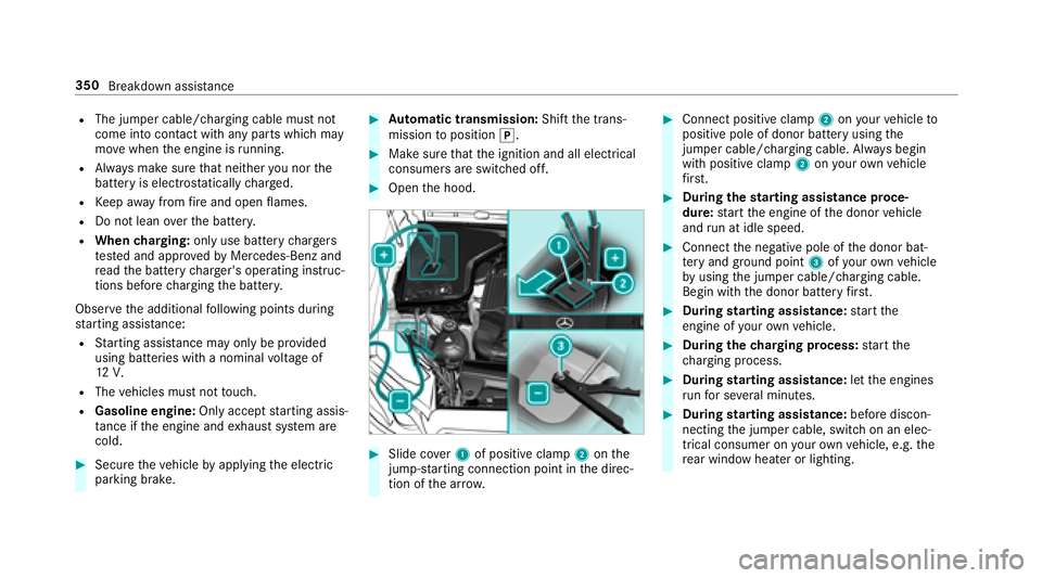
#Au tomatic transmission: Shiftthe trans‐
mission toposition j.
#Make sure that the ignition and all electrical
consumers are switched off.
#Open the hood.
#Slide co ver1 of positive clamp 2onthe
jump-s tarting connection point in the direc‐
tion of the ar row.
#Connect positive clamp 2onyour vehicle to
positive pole of donor battery using the
jumper cable/charging cable. Alw ays begin
with positive clamp 2onyour ow nve hicle
fi rs t.
#Du ring thest arting assist ance proce‐
dure: start the engine of the donor vehicle
and run at idle speed.
#Connect the negative pole of the donor bat‐
te ry and ground po int3 ofyour ow nve hicle
by using the jumper cable/charging cable.
Begin with the donor battery firs t.
#Du ring starting assist ance:start the
engine of your ow nve hicle.
#During thech arging process: start the
ch arging process.
#During starting assist ance:letthe engines
ru nfo r se veral minutes.
#During starting assist ance:before discon‐
necting the jumper cable, switch on an elec‐
trical consumer on your ow nve hicle, e.g. the
re ar wind owheater or lighting.
350
Breakdown assis tance
Page 353 of 506
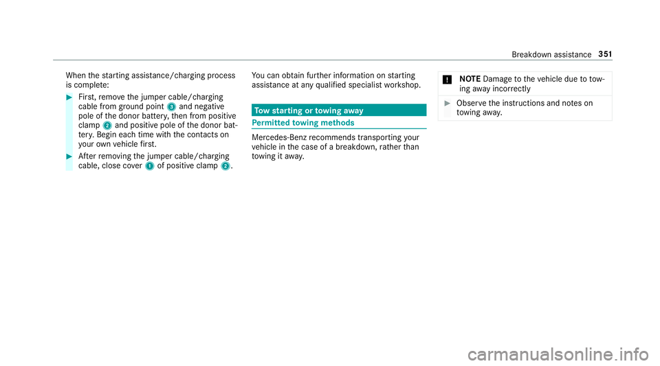
Whenthest arting assis tance/charging process
is compl ete:
#Fir st,re mo vethe jumper cable/charging
cable from ground point 3and negative
pole of the donor batter y,then from positive
clamp 2and positive pole of the donor bat‐
te ry. Begin each time with the conta cts on
yo ur ow nve hicle firs t.
#Af terre moving the jumper cable/charging
cable, close co ver1 of positive clamp 2.Yo
u can obtain fur ther information on starting
assis tance at any qualified specialist workshop.
To w starting or towing away
Perm itted towing me thods
Mercedes-Benz recommends transporting your
ve hicle in the case of a breakdown, rath er than
to wing it away. *
NO
TEDama getotheve hicle due to tow‐
ing away incor rectly
#Obser vethe instructions and no tes on
to wing away.
Breakdown assis tance 351
Page 490 of 506

Mirrors
see Outside mir rors
Mobile phone ...........................................2 24
Canc eling permission for Internet
connection .......................................... 300
Wi reless charging ................................ 122
Mobile phone see Android Auto
see Apple CarPlay™
see Telephone
Mobile phone voice recognition
St arting .............................................. .285
St opping ..............................................2 85
Model type ............................................... 392
MOEx tended tires .................................... 341
Multifunction display (on-board com‐
puter) ........................................................ 218
Multifunction steering wheel
Overview of buttons ............................ .216
Multifunction steering wheel
see Steering wheel Multimedia sy
stem .......................... 239, 247
Ac tivating/deactivating standby
mode .................................................. .165
Ad justing thevo lume .......................... .245
Calling up lists and menus ................... 242
Central cont rol elements .................... .239
Configuri ng displaysettings ................. 247
Main functions .....................................2 42
Overview ............................................. 239
R
e ar climate control ............................ 138
Re storing thefa ctory settings ............. 257
Switching the sound on/off ............... .244
N
Na vigation
Calling up the Digital Operator's
Manual ................................................ .281
Menu (on-board computer) .................. 221
Showing/hiding the menu .................. .258
Switching on ....................................... 258
Up dating the map data ........................ 279
Vo ice commands (Voice Cont rol Sys‐
te m) ..................................................... 231
Na vigation
see Destination see Destination entry
see Map
see
Route
see Route guidance
see Traf fic information
Na vigation announcements
Ac tivating/deactivating .......................2 69
Ad justing thevo lume .......................... .270
Re peating ............................................ 270
Switching audio fadeout on/off .......... 270
Switching on/off du ring a phone call .. 269
Na vigation messages
On-board computer ............................. 221
Ne arField Communication (NFC) .......... 284
Connecting the mobile phone tothe
multimedia sy stem .............................. 284
Switching Blue tooth
®audio equip‐
ment .................................................... 316
Switching mobile phones .................... 284
Ne utral
Selecting ............................................. 152
NFC see Near Field Communication (NFC)
Note s on breaking-in a new vehicle .......1 46
488
Index
Page 499 of 506
Telephone ................................................ .281
Ac tivating functions du ring a call ........ 286
Call and ringtone volume .................... .285
Calls with se veral participants ............ .286
Connecting a mobile phone (Near
Field Communication (NFC)) ...............2 84
Connecting a mob ilephone (Pass‐
ke y) .................................................... .283
Connecting a mobile phone (Secure
Simple Pairing) .................................... 283
Disconnecting a mobile phone ............ 284
Importing con tacts ..............................2 88
Incoming call during an existing call .... 286
Menu (on-board computer) .................. 224
Mobile phone voice recognition .......... 285
No tes .................................................. 282
Operating modes ................................. 282
Re ception and transmission volume .... 285
Swit ching mobile phones .................... 284
Swit ching mobile phones (Near Field
Communication (NFC)) ........................ 284
Te lephone menu overview .................. .281
Te lephone operation ............................ 285
Using Near Field Communication
(NFC) .......................................... ...
.....
.284 Vo
ice commands (Voice Cont rol Sys‐
te m) ..................................................... 233
Wi reless charging (mobile phone) ........ 122
Te lephone
see Mobile phone
Te lephone number
Dialing (on-board computer) ................ 224
Te lephony operating modes
Blue tooth
®Telephony .......................... 282
Te mp erature ............................................ 136
Te mp erature grade .................................. 372
Te xt messages ......................................... 289
Calling a message sender .................... 291
Changing folders ................................ .291
Composing .......................................... 290
Confi guring the displa yedte xt mes‐
sage s ................................................... 290
Deleting ............................................... 291
Drafts .................................................. 291
No tes .................................................. 289
Options ................................................ 291
Outbox .................................................2 91
Re ad-aloud function ............................ 290
Re ading ........ ...
...................................
.290 Re
plying .............................................. .291
Sending ............................................... 290
Vo ice commands (Voice Cont rol Sys‐
te m) ..................................................... 236
Through-loading feature
see Seat
Ti e-d owney es .......................................... .111
Time Manual time setting ............................. 248
Setting summer time ........................... 248
Setting the time and date automati‐
cally ..................................................... 247
Setting the time zone .......................... 248
Setting the time/date form at .............. 248
TIN (Tire Identi fication Number) ............3 73
Ti re and Loading Information placard ... 367
Ti re ch aracteristics ................................. 375
Ti re information table .............................367
Ti re labeling ............................................ .372
Characteristics .................................... 375
DO T,Tire Identification Number (TIN)
.............................................................3 73
Load index ........................................... 375
Index 497
Page 505 of 506
DOT,Tire Identification Number (TIN)
.............................................................3 73
Flat tire ................................................ 340
Inter changing ...................................... 382
Load ind ex........................................... 375
Load-bearing capacity ......................... 375
Maximum tire load ...............................3 74
Maximum tire pressure ........................ 374
MOExtended tires ................................ 341
Mounting ............................................. 387
No ise .................................................. .360
No tes on mounting .............................. 380
Overview of tire labeling ......................3 72
Re moving ............................................ 387
Re placing ............................................ 380
Re starting the tire pressure monitor‐
ing sy stem .......................................... .367
Selection ............................................. 380
Snow chains ........................................ 361
Speed rating ........................................ 375
St oring ................................................ 383
Te mp erature grade .............................. 372
Ti re and Loading Info rmation placard .. 367
Ti re characteristics .............................. 375
Ti re
pressure (n
ote s) ............................3 61Ti
re pressure monitoring sy stem
(function) ............................................. 365
Ti re pressure table .............................. 363
Ti re Quality Grading ............................. 372
Ti re size designation ............................3 75
TIREFIT kit ...........................................3 42
Tr action grade .................................... .372
Tr ead wear grade ................................ .372
Un usual handling characteristics ........ 360
Wi -Fi
Overview ............................................. 249
Setting ................................................. 249
Setting up a hotspot ............................ 250
Setting up an Internet connection ....... 297
Wi ndow airbag ...........................................3 8
Wi ndow lif ter
see Side windo ws
Wi ndo ws
see Side windo ws
Wi ndo ws(Care) ...................................... .336
Wi ndshield
Defrosting ............................................ 136
Infrared reflective ................................ 135
Re placing the wiper blades .................. 130 Wi
ndshield heater .................................... 141
Wi ndshield heating
see Windshield hea ter
Wi ndshield washer fluid .........................3 98
No tes ........................ .......................... 398
Wi ndshield w
a sher sy stem
Re filling .............................................. .332
Wi ndshield wipers
Re placing the wiper blades .................. 130
Switching on/off ................................. 129
Wi nter operation
Snow chains ........................................ 361
Wi nter tires
Setting the permanent speed limit ...... 177
Wi per blades
Ca re .................................................... 336
Changing ............................................. 130
Wire lesscharging
Fu nction/no tes ................................... 120
Mobile phone ....................................... 122
Wire lessvehicle co mponents
Declaration of con form ity ...................... 23
Index 503