Page 438 of 593

#
Use a tow bar. #
Make sure that thesteering wheel can
mo vefreely, before towing theve hicle
aw ay. *
NO
TEDama gedue toexcessive tracti ve
po wer If
yo u pull away sharpl y,the tractive po wer
may be too high and theve hicles could be
damaged. #
Pull away slowly and smoo thly. Loading the
vehicle for transport #
Obser vethe no tes on towing away
( → page 433). #
Connect theto w bar totheto wing eye in
order toload theve hicle.
% You can also attach theto w bar tothe trailer
hitch. #
Vehicles with automatic transmission:
shift the automatic transmission toposition
i.
% Ve
hicles with automatic transmission:
th e automatic transmission may be loc ked in
position jintheeve nt of dama getothe
electrical sy stem. Toshift toi , pr ovide the
on-board electrical sy stem with po wer
( → page 430). #
Load theve hicle onto the transpor ter. #
Vehicles with automatic transmission:
shift the automatic transmission toposition
j. #
Use the electric parking brake tosecure the
ve hicle against rolling away. #
Only secure theve hicle bythe wheels. Ve
hicles with ADS PLUS (Adaptive Damping
Sy stem PLUS) &
WARNING Risk of an accident when
transporting vehicles with Adaptive
Damping Sy stem PLUS
The reduced damping forc es on theve hicle
being transpor ted can cause theve hicle/
trailer combination tostart toswing.
As a result, when transporting vehicles with
th eAd aptive Damping Sy stem PLUS, the
ve hicle/trailer combination may start toskid.
Consequentl y,yo u could lose cont rol of your
ve hicle. #
When transporting, ensure that:
R theve hicle has been loaded onto
th e transpor ter cor rectly
R theve hicle is secured at all four
wheels with suitable tensioning
st ra ps
R the maximum permissible speed of
60 km/h is not exceeded when
transporting Breakdown assis
tance 435
Page 439 of 593
*
NO
TEDama getotheve hicle from secur‐
ing it incor rectly #
After loading, theve hicle must be
secured on all four wheels. Otherwise,
th eve hicle could be damaged. #
A minimum dis tance of 20 cm up wards
and 10cm down wards must be kept to
th e transport platform. #
Secure theve hicle on all four wheels af ter
loading.
4MATIC vehicles/ vehicles with automatic
transmission #
Make sure that the front and rear axles come
to rest on the same transpor tation vehicle.
* NO
TEDama getothe driv etra in due to
incor rect positioning #
Do not position theve hicle abo vethe
connection point of the transport vehi‐
cle. To
wing eye To
wing eye1 is attached tothe edge of the
boot under the boot floor. Installing
theto wing eye #
Press the mark on co ver1 inwa rds and
re mo ve. #
Screw intheto wing eyeclockwise as far as it
will go and tighten.
Ve hicles with a trailer hitch: vehicles with a
trailer hitch do not ha veare ar brac ketfo rthe 436
Breakdown assis tance
Page 440 of 593

to
wing eye. Fasten theto w bar tothe trailer
hitch.
% Make sure that co ver1 engages in the
bumper when youre mo vetheto wing eye.
* NO
TEDama gedue toincor rect use of
th eto wing eye When a
towing eye is used toreco ver a vehi‐
cle, theve hicle may be damaged in the proc‐
ess. #
Only use theto wing eyeto to waw ay or
to w start theve hicle. To
w starting theve hicle (eme rgency engine
st art) Ve
hicles with automatic transmission
* NO
TEDama getothe automatic trans‐
mission due to tow-starting The automatic transmission may be damaged
in the process of tow- starting vehicles with
automatic transmission. #
Vehicles with automatic transmission
must not be tow- star ted. #
Vehicles with automatic transmission must
not be tow- star ted. Electrical fuses
Note
s on electrical fuses &
WARNING Risk of accident and inju ry
due to ov erloaded lines
If yo u manipulate or bridge a faulty fuse or if
yo ure place it with a fuse with a higher
amperage, the electric line could be overloa‐
ded.
This could result in a fire. #
Alw aysre place faulty fuses with speci‐
fi ed new fuses conta iningthe cor rect
amperage. *
NO
TEDama gedue toincor rect fuses Electrical components or sy
stems may be
damaged byincor rect fuses, or their func‐
tionality may be significant lyimpaired. #
Only use fuses that ha vebeen appr oved
by Mercedes-Benz and which ha vethe
cor rect fuse rating. Blown fuses mu
stbe replaced with fuses of the
same rating, which you can recognise bythe col‐
our and fuse rating. The fuse ratings and fu rther
information tobe obser ved are lis ted in the fuse
assignment diagram.
Fu se assignment diag ram: onthe fuse box in
th e boot (→ page 439).
* NO
TEDama geor malfunctions caused
by moisture Moisture may cause dama
getothe electrical
sy stem or cause it tomalfunction. Breakdown assi
stance 437
Page 451 of 593

Count
ryRadio equipment appr oval
number
United
Arab Emi‐
ra tes TRA
REGISTERED NO: ER3
7156/15.
DEALER NO: DA00470 74/10
Vi etnam Schrader Electronics Ltd.
Model:
AG5SP4
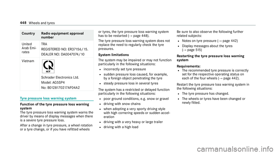
No: B0 1281702 17AF04A2 Ty
re pressure loss warning sy stem Fu
nction of the ty repressure loss warning
sy stem
The tyre pressure loss warning sy stem warnsthe
driver bymeans of display messa ges when there
is a se vere tyre pressu reloss.
Af ter a change in tyre pressure, a wheel rotation
or a tyre change, or if you ha verefitted wheels or tyres,
the tyre pressure loss warning sy stem
has tobe restar ted (→ page 448).
The tyre pressu reloss warning sy stem does not
re place the need toregular lych eck the tyre
pressures.
Sy stem limitations
The sy stem may be impaired or may not function
particular lyin thefo llowing situations:
R incor rectly set tyre pressure
R sudden pressure loss caused, forex ample,
by afo re ign object penetrating the tyre
R steady pressure loss in se veral tyres
The sy stem has a restricted or del ayed function
particularly in thefo llowing situations:
R poor ground cond itions, e.g. snow or gr avel
R driving with snow chains
R when adopting a very sporty driving style
with high cornering speeds or sudden accel‐
eration
R driving with a very heavy or lar getrailer
R driving wi tha high load Be sure
toalso obse rveth efo llowing fur ther
re lated subjects:
R Notes on tyre pressure (→ page442)
R Displ aymessa ges about the tyres
(→ page 515)
Rest arting the ty repressure loss warning
sy stem
Requ irements:
R The recommended tyre pressure is cor rectly
set forth ere spective operating status on
each of thefo ur wheels (→ page442).
Re start the tyre pressure loss warning sy stem in
th efo llowing situations:
R The tyre pressure has changed.
R The wheels or tyres ha vebeen changed or
newly fitted. 448
Wheels and tyres
Page 478 of 593

Height when opened
Model
1 1Height
when
opened
E 200 4MATIC
E 220 d 4MATIC 17
47 mm
E 350
E 350 d 17
41 mm
E 400 d 4MATIC
E 450 4MATIC 17
48 mm
All other models 1740 mm Ve
hicle dimensions All models
Ve
hicle lengt h4 826 mm
Ve hicle width including out‐
side mir rors 2055 mm All models
Ve
hicle width excluding out‐
side mir rors 18
60 mm
Wheelbase 2873 mm Ve
hicle height Model
E 200 4MATIC
E 220 d 4MATIC
14
38 mm
E 350
E 350 d 14
31 mm
E 400 d 4MATIC
E 450 4MATIC 14
39 mm
All other models 1430 mm We
ights and loads Please no
tethat forth e specified vehicle data:
R items of optional equipment increase the
unladen weight and reduce the pa yload.
R vehicle-specific weight information can be
fo und on theve hicle identification plate .
Ro of load All models
Maximum
roof load 75kg Tr
ailer hitch Gene
ral no tes on the trailer hit ch Not all models can be used
for trailer operation
(→ page 253).
Modi fications tothe engine cooling sy stem may
be necessar y,depending on theve hicle model.
The retrofitting of a trailer hitch is only pe rmissi‐
ble if a towing capacity is specified in your vehi‐
cle documents. Te
ch nical da ta475
Page 479 of 593
Fu
rther information can be obtained at a quali‐
fi ed specialist workshop. Mounting dimensions
1
Fastening points
2 Overhang dimension
3 Rear axle centre line The
overhang dimension and fastening points
are valid for a trailer hitch ins talled at thefa c‐
to ry. Model
2 2Over‐
hang dimen‐ sion
All model s1 203 mm Pe
rm issible towing capacity The
tongue weight is not included in theto wing
capacity.
Pe rm issible towing capacit y,braked (at a
minimum start-off gradeability of 8%) Model
Perm issible towing
capacit y,braked
All models 476
Tech nical da ta
Page 480 of 593
Pe
rm issible towing capacit y,braked (at a
minimum start-off gradeability of 12%) Model
Perm issible towing
capacit y,braked
All models 1800 kg Pe
rm issible towing capacit y,unbraked Model
Perm issible towing
capacit y,unbraked
All model s7 50kg Maximum
tongue weight *
NO
TEDama gecaused bythe trailer
coming loose If
th eto ngue weight used is too lo w,the
trailer may come loose. #
The tongue weight must not be below
50 kg. #
Use a tongue weight that is as close as
possible tothe maximum permissible
to ngue weight. Maximum
tongue weight Model
All models
75kg Pe
rm issible rear axle load during trailer
operation Axle load
Model
Axle load
E 200 1240 kg
E 200 4MATIC 1250 kg
E 220 d1 290kg
E 220 d 4MATIC 1295 kg
E 300 1265 kg
E 300 d1 285kg Model
Axle load
E 350 1270 kg
E 350 d1 255kg
E 400 d 4MATIC 1275 kg
E 450 4MATIC 1270 kg Te
ch nical da ta477
Page 496 of 593

Display messages
Possible causes/consequences and M
MSolutions
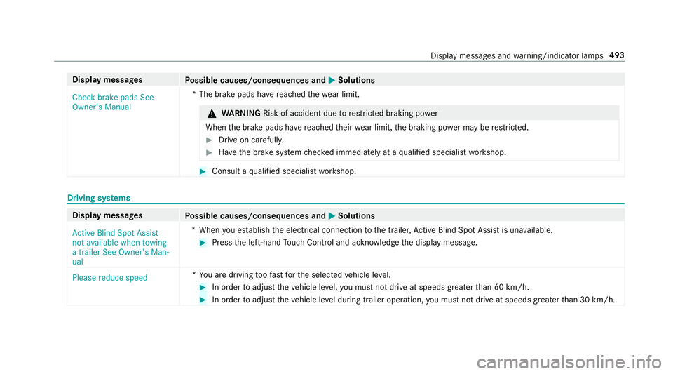
Check brake pads See
Owner's Manual *T
he brake pads ha vereached thewe ar limit. &
WARNING Risk of accident due torestricted braking po wer
When the brake pads ha vereached their wear limit, the braking po wer may be restricted. #
Drive on carefully. #
Have the brake sy stem checked immediately at a qualified specialist workshop. #
Consult a qualified specialist workshop. Driving sy
stems Display messages
Possible causes/consequences and M
MSolutions
Active Blind Spot Assist
not available when towing
a trailer See Owner's Man-
ual *W
hen you es tablish the electrical connection tothe trailer, Active Blind Spot Assi stis una vailable. #
Press the left-hand Touch Control and ackn owledge the display message.
Please reduce speed *Y
ou are driving toofast forth e selected vehicle le vel. #
In order toadjust theve hicle le vel,yo u must not drive at speeds greater than 60 km/h. #
In order toadjust theve hicle le vel during trailer operation, you must not drive at speeds greater than 30 km/h. Display messages and
warning/indicator lamps 493