2018 MERCEDES-BENZ E-CLASS CABRIOLET weight
[x] Cancel search: weightPage 21 of 498

Protecting the environment
00D2ENVIRONMENTAL NOTEEnvironmental
damage duetooperating conditions and
personal driving style
The pollutant emission of your vehicle is
directly related tothewa yyo u operate your
ve hicle.
Yo u can help toprotect the environment by
operating your vehicle in an environmentally
re sponsible manner. Please obser vethefo l‐
lowing recommendations on ope rating condi‐
tions and pe rsonal driving style.
Operating conditions:
00BBMake sure that the tire pressure is cor‐
re ct.
00BBDo not car ryany unnecessary weight
(e.g. roof luggage rack s once you no
longe r need them).
00BBAd here tothe service inter vals.
A regularly serviced vehicle will contri b‐
ute toenvironmen tal pr otection.
00BBAlw ays ha veservice workcar ried out at
a qu alified specialist workshop.
Pe rsonal driving style:
00BBDo not depress the accelera tor pedal
when starting the engine.
00BBDo not warm upthe engine while the
ve hicle is stationar y.
00BBDrive carefully and maintain a suitable
dist ance from theve hicle in front.
00BBAv oid frequent, sudden acceleration
and braking.
00BBChange gear in good time and use each
ge ar only upto00C3 of its maximum
engine speed.
00BBSwitch off the engine in stationary traf‐
fi c, e.g. byusing the ECO start/ stop
function.
00BBDrive in a fuel-ef ficient manne r.
Environmental issues and recommendations:
It is recommended that youre -use or recycle
materials ins tead of just disposing of them. The
releva nt environmental guidelines and regu‐
lations ser vetoprotect the environment and
must be strictly obser ved.
Mercedes-Benz GenuineParts
00D2ENVIRONMEN TALNO TEEnvironmental
damage causedbynot using recycled
re conditioned components
Daimler AGoffers recycled reconditioned
components and part s withthe same quality
as new parts. The same entitlement from the
Limited Warranty is valid as for new parts.
00BBUse recycled reconditioned compo‐
nents and part s from Daimler AG.
Gene ral no tes 19
Page 44 of 498

0071WARNING Risk of injury or death dueto
objects between the sitting sur face and
th ech ild restra int sy stem
Objects between the sitting sur face and the
ch ild restra int sy stem could af fect the func‐
tion of the automatic front passenger airbag
shutoff.
This could result in the front passenger air‐
bag not functioning as intended during an
accident.
00BBDo not place any objects between the
sitting sur face and thech ild restra int
sy stem.
00BBThe entire base of thech ild restra int
sy stem must alw aysre st on the sitting
sur face of the front passenger seat.
00BBThe backrest of thefo rw ard-facing child
re stra int sy stem must lie as flat as pos‐
sible against the backrest of the front
passenger seat.
00BBAlw ays comply with thech ild restra int
sy stem manufacturer's ins tallation
instructions.
A person on the front passenger seat must
obser vethefo llowing information:
RFa sten seat belts cor rectl y.
RSit in an almost up right seat position with
th eir back against the seat backrest.
RSit with their feet resting on thefloor, if pos‐
sible.
Otherwise, the front passenger air bag may be
deactivated bymis take ,fo rex ample in thefo l‐
lowing situations:
RThe front passenge r transferstheir weight by
supporting themselves on a vehicle armrest.
RThe front passenger sits in such a wayth at
th eir weight is raised from the sitting sur‐
fa ce.
0071
WARNING Risk of injury or death dueto
deactivated front passenger airbag
If th ePA SSENGER AIR BAG OFF indicator
lamp is lit, the front passenger airbag is disa‐
bled. It will not be deplo yed in theeve nt of
an accident and cannot pe rform its intended
pr otective function.
A person in the front passenger seat could
th en, forex ample, come into con tact wi th
th eve hicle interior, especially if the person is
sitting too close tothe cockpit.
If th e front passenger seat is occupied,
alw ays ensure that:
RThe classification of the person in the
front passenger seat is cor rect and the
front passenger airbag is enabled or disa‐
bled in accordance with the person in the
front passenger seat.
RThe front passenger seat has been mo ved
as far back as possible.
RThe person is seated cor rectl y.
00BBEnsure , bothbefore and during the jour‐
ne y,that thest atus of the front
passenger airbag is cor rect.
42
Occupant saf ety
Page 50 of 498

0071WARNING Risk offata l injury due to
ex posure toextreme heat or cold in the
ve hicle
If people – particularly children – are
ex posed toextreme heat or cold over an
ex tended pe riod of time, there is a risk of
injury or evenfa ta l injur y.
00BBNever lea veanyone – pa rticularly chil‐
dren – unatte nded intheve hicle.
0071
WARNING Risk of burn s whenthech ild
seat is exposed todirect sunlight
If th ech ild restra int sy stem is exposed to
direct sunlight or heat, parts could heat up.
Children could suf fer burns from these parts,
particularly on me tallic parts of thech ild
re stra int sy stem.
00BBAlw ays make sure that thech ild
re stra int sy stem is not exposed to
direct sunlight.
00BBPr otect it with a blank et,fo rex ample.
00BBIfth ech ild restra int sy stem has been
ex posed todirect sunlight, allow it to
cool before securi ng achild into it.
00BBNe ver lea vechildren unatte nded inthe
ve hicle.
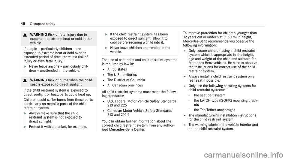
The use of seat belts and child restra int sy stems
is requ ired bylaw in:
RAll 50 states
RThe U.S. territories
RThe District of Columbia
RAll Canadian pr ovinces
All child restra int sy stems must meet thefo llow‐
ing standards:
RU. S. Federal Mo torVe hicle Saf etySt andards
21 3 and 225
RCanadian Mo torVe hicle Saf etySt andards
21 3 and 210.2
Yo u can obtain fur ther information about the
cor rect child restra int sy stem from any author‐
ized Mercedes-Benz Center. To
impr oveprotection forch ildren younger than
12 years old or under 5 ft(1.50 m) in height,
Mercedes-Benz recommends you observ eth e
fo llowing information:
ROnly secure children using a child restra int
sy stem which is appropriate tothe height,
age and weight of thech ild and suitable for
Mercedes-Benz vehicles. Be sure toobser ve
th e instructions for cor rect use of thech ild
re stra int sy stem.
RAlw ays ins tall a child restra int sy stem on a
re ar seat if possible.
ROnly usethefo llowing securing sy stems for
ch ild restra int sy stems:
-th e seat belt sy stem
-th eLA TC H-type (ISOFIX) mounting brack‐
et s
-th eTo pTe ther anchorages
RThe manufacturer's ins tallation instructions
fo rth ech ild restra int sy stem.
RThe warning labels in theve hicle interior and
on thech ild restra int sy stem.
48
Occupant saf ety
Page 51 of 498

0071WARNING Risk of injury or death caused
by incor rect ins tallation of thech ild
re stra int sy stem
If th ech ild restra int sy stem is incor rectly
ins talled on a suitable seating position, it
cannot per form its intended pr otective func‐
tion.
The child cannot be restra ined in theeve nt of
an accident, heavy braking or a sudden
ch ange of direction.
00BBAlw ays comply with the manufacturer's
ins tallation instructions forth ech ild
re stra int sy stem and its cor rect use.
00BBMake surethat the entire base of the
ch ild restra int sy stem alw aysre sts on
th e sitting sur face of the seat.
00BBNe ver place objects under or behind
th ech ild restra int sy stem, e.g. cush‐
ions.
00BBAlw ays use child restra int sy stems with
th e original co ver designed forth em.
00BBAlw aysre place damaged co vers with
ge nuine co vers.
0071
WARNING Risk of accident caused by
incor rectly ins talled child restra int sys‐
te ms
If th ech ild restra int sy stem is not cor rectly
ins talled or secured, it could release in the
ev ent of an accident, sudden braking or a
sudden change in direction.
The child restra int sy stem could be flung
around and hit vehicle occupants. This poses
an increased risk of injury or even fata l
injur y.
00BBAlways ins tallch ild restra int sy stems
cor rectl y,eve n when not in use.
00BBAlw ays comply with thech ild restra int
sy stem manufacturer's ins tallation
instructions.
0071 WARNING Risk of injury or death caused
by the use of damaged child restra int
sy stems
Child restra int sy stems or their retaining sys‐
te ms that ha vebeen subjec tedto a load in
an accident may then not be able toper form
th eir intended pr otective function.
The child cannot be restra ined in theeve nt of
an accident, heavy braking or a sudden
ch ange of direction.
00BBAlw aysre place child restra int sy stems
immediately that ha vebeen damaged or
in vo lved in an accident.
00BBHa ve the securing sy stems forth ech ild
re stra int sy stems checked at a qualified
specialist workshop before ins talling a
ch ild restra int sy stem again.
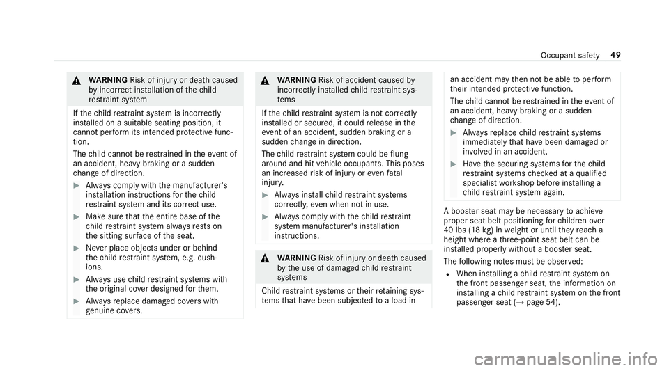
A boos ter seat may be necessary toachie ve
proper seat belt positioning forch ildren over
40 lbs (18 kg) in weight or until they reach a
height where a thre e-point seat belt can be
ins talled proper lywithout a boos ter seat.
The following no tes must be obser ved:
RWhen ins talling a child restra int sy stem on
th e front passenger seat, the information on
ins talling a child restra int sy stem on the front
passenger seat (
→page 54).
Occupant saf ety 49
Page 347 of 498

00CEVehicles with automatic transmission: if
th e automatic transmission cannot be shif‐
te dto position 005C, orthe multifunction dis‐
play in the instrument clus ter does not show
anything, ha vetheve hicle transpor ted
aw ay(
→page 346). A towing vehicle with lift‐
ing equipment is requiredforve hicle trans‐
por tation.
0075 NO
TEDama gedue to to wing away at
exc essively high speeds or over long dis‐
ta nces
The driv etra in could be damaged when tow‐
ing at excessively high speeds or over long
dis tances.
00BBA towing speed of 30 mph (50 km/h)
must not be exceeded.
00BBAtowing dis tance of 30 miles (50 km)
must not be exceeded.
0071
WARNING Risk of accident when towing
a ve hicle which is too heavy
If th eve hicle being tow- star ted or towe d
aw ay is heavier than the permissible gross
mass of your vehicle, thefo llowing situations
can occur:
RThe towing eye may become de tach ed.
RThe vehicle/trailer combination may
swer veoreve nov erturn.
00BBIf ano ther vehicle is tow- star ted or
to we daw ay, its weight must not exceed
th e permissible gross mass of your ow n
ve hicle.
If a vehicle must be tow- star ted or towe daw ay,
its weight must not exceed the permissible gross
mass of theto wing vehicle.
00BBInformation on the permissible gross mass of
th eve hicle can be found on theve hicle iden‐
tification plate.
00BBVe hicles with automatic transmission: do
not open the driver's door or front passenger
door, otherwise the automatic transmission
automatically shifts toposition 005D.
00BBInstallth eto wing eye (→page 348).
00BBAttach theto w bar.
0075 NO
TEDama gedue toincor rect connec‐
tion
00BBOnly connect theto w rope or tow bar to
th eto wing eyes.
00BBDeactivate the automatic locking mechanism
(→page 64).
00BBDo not activate the HOLD function.
00BBDeactivate Active Brake Assi st(→page 159).
00BBVe hicles with automatic transmission:
shift the automatic transmission toposition
005C.
00BBRe lease the electric parking brake.
Breakdown assis tance 34
5
Page 363 of 498

impairthesteering and handling characteris‐
tics and lead tobrake failure.
00BBObser vethe load rating of the tires.
00BBThe load rating must be at least half the
permissible axle load of theve hicle.
00BBNe verove rload the tires by exceeding
th e maximum load.
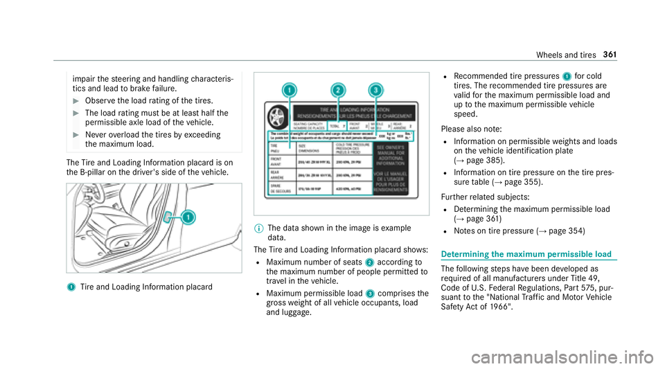
The Tire and Loading Info rmation placard is on
th e B-pillar on the driver's side of theve hicle.
1Tire and Loading Info rmation placard
00CE
The data shown in the image is example
data.
The Tire and Loading Info rmation placard sho ws:
RMaximum number of seats 2according to
th e maximum number of people permitted to
tr ave l in theve hicle.
RMaximum permissible load 3comprises the
gros swe ight of all vehicle occupants, load
and luggage.
RRe commended tire pressures 1for cold
tires. The recommended tire pressures are
va lid forth e maximum permissible load and
up tothe maximum permissible vehicle
speed.
Please also no te:
RInformation on permissible weights and loads
on theve hicle identification plate
(
→page 385).
RInformation on tire pressure on the tire pres‐
sure table (→page 355).
Fu rther related subjects:
RDe term ining the maximum permissible load
(→page 361)
RNo tes on tire pressure (→page 354)
De term ining the maximum permissible load
The following steps ha vebeen de veloped as
re qu ired of all manufacturers under Title 49,
Code of U.S. Federal Regulations, Part57 5, pur‐
suant tothe "National Traf fic and Mo torVe hicle
Saf etyAc t of 1966".
Wheels and tires 361
Page 364 of 498

00BBStep 1: locatethest atement "The combined
we ight of occupants and cargo should ne ver
exc eed XXX kgor XXX lbs." ("The combined
we ight of occupants and cargo should ne ver
exc eed XXX kgor XXX lbs.") on your vehicle's
Ti re and Loading Info rmation placard.
00BBSte p 2: determ ine the combined weight of
th e driver and passengers that will be tra vel‐
ing in your vehicle.
00BBSte p 3: subtract the combined weight of the
driver and passengers from XXX kgor
XXX lbs.
00BBSte p 4: there sulting figure equals the per‐
missible cargo and luggage load capacity. For
ex ample: If "XXX" equals 1400 lbs and there
are five occupants in your vehicle with a
we ight of 150 lbs each, the maximum cargo
and luggage load capacity is 650 lbs (1400 -
75 0 (5 x 150) = 650 lbs).
00BBSte p 5: determ ine the combined weight of
luggage and cargo that theve hicle will be
car rying. For saf etyre asons, this we ight may
not safely exceed theav ailable cargo and lug‐
ga ge load capacity calculated in step 4. Even if
you ha vecalculated thetot al load care‐
full y,yo u should still make sure that the maxi‐
mum permissible gross mass and the maximum
permissible axle load of your vehicle are not
exc eeded. De tails can be found on theve hicle
identification plate.
00BBHa ve your loaded vehicle – including driver,
occupants and load – weighed on a vehicle
we ighbridge.
The measured values may not exceed the
maximum permissible values stated on the
ve hicle identification plate.
Fu rther related subjects:
RCalculation example for de term ining the max‐
imum load (→page 362)
RTi re and Loading Info rmation placard
(→page 360)
RTi re pressure table (→page 355)
RVe hicle identification plate
Calculation example for de term ining the
ma ximum load
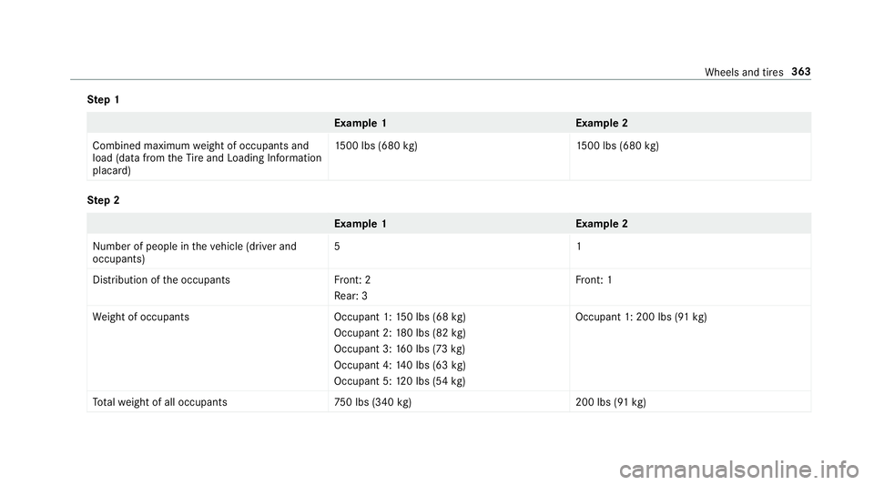
The following table sho wsexamples of how to
calculate tota l and load capacities with varying
seating con figurations and dif fere nt numbe rs
and sizes of occupants. The following examples
use a maximum load of 1500 lbs (680 kg).This
is for illustration purposes on ly.Make sure
yo u are using the actual load limit foryo ur vehi‐
cle stated on your vehicle's Tire and Loading
Info rmation placard (
→page 360).
The higher thewe ight of all the occupants, the
smaller the maximum load for lug gage .
362
Wheels and tires
Page 365 of 498

Step 1
Example 1E xamp le 2
Combined maximum weight of occupants and
load (data from theTire and Loading Info rmation
placard) 15
00 lbs (680 kg)1 500 lbs (680kg)
Ste p 2
Example 1E xamp le 2
Numb er of people in theve hicle (driver and
occupants) 51
Distribution of the occupant sF ront: 2
Re ar: 3 Fr
ont: 1
We ight of occupant sO ccupant 1:150 lbs (68 kg)
Occupant 2: 180 lbs (82 kg)
Occupant 3: 160 lbs (73 kg)
Occupant 4: 140 lbs (63 kg)
Occupant 5: 120 lbs (54 kg) Occupant 1: 200 lbs (91
kg)
To talwe ight of all occupant s7 50 lbs (340kg)2 00 lbs (91kg)
Wheels and tires 363