Page 379 of 498

Setting upthefo lding wheel chock
Prepa ring theve hicle for a wheel change
Re quirementsRThe requ ired tire-change tool kit is available.
If yo ur vehicle is not equipped with the tire-
ch ange tool kit, consult a qualified specialist
wo rkshop tofind out about suitable tools.
RThe vehicle is not on a slope.
RThe vehicle is on solid, non-slippery and le vel
ground .
00BBApplythe electric parking brake manually.
00BBMo vethe front wheels tothest ra ight-ahead
position.
00BBVe hicles with automatic transmission:
shift into position 005D.
00BBVehicles with AIR BODY CONT ROL:set the
normal vehicle le vel (→page 173).
00BBSwitch off the engine.
00BBMake sure that the engine cannot bestar ted.
00BBPlace choc ks orother suitable items under
th e front and rear of the wheel that is diago‐
nally opposite the wheel youwish tochange.
00BBRe mo vethe hub caps if necessary
(→page 377).
00BBRa ising theve hicle (→page 378).
Re moving and in stalling hub caps
Re quirement:RThe vehicle is prepared for a wheel change
(→page 377).
Plas tic hub cap
00BBToremo ve:turn the center co ver of the hub
cap anti-clockwise and remo vethe hub cap.
00BBTo install: make sure that the center co ver of
th e hub cap is turned anti-clockwise.
00BBPo sition the hub cap and turn the center
co ver clockwise until the hub cap engages
ph ysically and audibly.
Wheels and tires 37
7
Page 380 of 498

Aluminum hub cap
00BBToremo ve:position soc ket2 on hub cap
1.
00CE The soc ket can be found inthe tire-change
to ol kit.
00BBPo sition wheel spanner 3on soc ket2.
00BBUsing wheel spanner 3, turn hub cap1
counter-clo ckwise and remo veit.
00BBTo install: position hub cap 1and turn until
it is comple tely flush withth e wheel.
00BBPo sition soc ket2 on hub cap 1.
00BBAttach wheel spanner 3tosoc ket2 and
tighten the hub cap clockwise.
Specified tightening torq ue: 18lb-ft
(25 Nm).
00BBRa ise theve hicle (→page 378).
Ra ising theve hicle when changing a wheel
Re quirements:RThere are no persons in theve hicle.
RThe vehicle has been prepared for a wheel
ch ange (→page 377).
RThe hub caps ha vebeen remo ved
(→page 377).
Impor tant no tes on using the jack:
Ronly use theve hicle-specific jack that has
been tested and appr ovedby Mercedes-Benz
to raise theve hicle.
Rthe jack is only designed forra ising and hold‐
ing theve hicle for a short time while a wheel
is being changed and not for maintenance
wo rkunder theve hicle.
Rthe jack must be placed on a firm ,fl at and
non-slip sur face. If necessar y,use a lar ge,
load-bearing, non-slip underla y.
Rthefo ot ofthe jack must be positioned verti‐
cally under the jack support point.
Ru les of conduct when theve hicle is raised:
RNe ver place your hands or feet under the
ve hicle.
RDo not lie under theve hicle.
RDo not start the engine and do not release
th e electric parking brake.
RDo not open or close any doors or the trunk
lid.
37 8
Wheels and tires
Page 381 of 498

00BBUsingthe wheel wrench, loosen the wheel
bolts on the wheel youwish tochange by
about one full turn. Do not unscr ewthe bolts
comple tely.Po sition of jack support points
0071
WARNING Risk of injury from incorrect
positioning of the jack
If yo u do not position the jack cor rectly at
th e appropriate jacking point of theve hicle,
th e jack could tip with theve hicle raised.
00BBOnly position the jack at the appropri‐
ate jacking point of theve hicle. The
base of the jack must be positioned ver‐
tically under the jacking point of the
ve hicle.
0075 NO
TEVehicle damage from the jack
Ifyo u do not position the jack cor rectly at
th e appropriate jack support point of the
ve hicle, the jack could tip over with theve hi‐
cle raised.
00BBThe jack is designed exclusively for
jacking up theve hicle at the jack sup‐
port points.
00BBTa ke thera tchet ring spanner out of the tire-
ch ange tool kit and place it on the he xagon
nut of the jack so that the lettering "AUF" is
visible.
Wheels and tires 37
9
Page 382 of 498

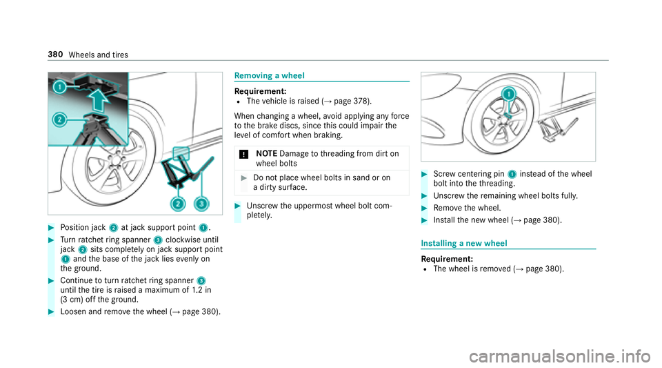
00BBPosition jack 2at jack support point 1.
00BBTurn ratchet ring spanner 3clockwise until
jack 2sits comple tely on ja cksupport point
1 and the base of the jack lies evenly on
th e ground.
00BBContinue toturn ratchet ring spanner 3
until the tire is raised a maximum of 1.2 in
(3 cm) off the ground.
00BBLoosen and remo vethe wheel (→page 380).
Re moving a wheel
Requirement:RThe vehicle is raised (→page 378).
When changing a wheel, avoid applying any forc e
to the brake discs, since this could impair the
le ve l of com fort when braking.
0075 NO
TEDama getothre ading from dirt on
wheel bolts
00BBDo not place wheel bolts in sand or on
a dirty sur face.
00BBUn scr ew the uppermost wheel bolt com‐
ple tely.
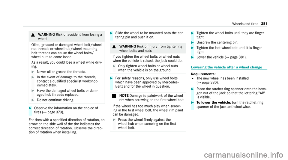
00BBScr ew centering pin 1instead of the wheel
bolt into theth re ading.
00BBUn scr ew there maining wheel bolts fully.
00BBRe mo vethe wheel.
00BBIns tallth e new wheel (→page 380).
Installing a new wheel
Re quirement:RThe wheel is remo ved (→page 380).
380
Wheels and tires
Page 383 of 498

0071WARNING Risk of accident from losing a
wheel
Oiled, greased or damaged wheel bolt/wheel
nut thre ads or wheel hub/wheel mounting
bolt thre ads can cause the wheel bolts/
wheel nuts tocome loose.
As a result, you could lose a wheel while driv‐
ing.
00BBNe ver oil or grease theth re ads.
00BBIn theeve nt of damage totheth re ads,
con tact a qualified specialist workshop
immediatel y.
00BBHave the damaged wheel bolts or dam‐
aged hub thre ads replaced.
00BBDo not continue driving.
00BBObser vethe information on thech oice of
tires (→page 373).
Fo r tires with a specified direction of rotation, an
ar row onthe side wall of the tire indicates the
cor rect dire ction of rotation. Observ eth e direc‐
tion of rotation when ins talling.
00BBSlide the wheel tobe mounted onto the cen‐
te ring pin and push it on.
0071
WARNING Risk of injury from tightening
wheel bolts and nuts
If yo u tighten the wheel bolts or wheel nuts
when theve hicle is raised, the jack could tip.
00BBOnly tighten wheel bolts or wheel nuts
when theve hicle is on the ground.
00BBFo r saf etyre asons, only use wheel bolts
which ha vebeen appr ovedby Mercedes-
Benz and forth e wheel in question.
0075 NO
TEDama getopaintwork of the wheel
ri m when scr ewing on thefirs t wheel bolt
If th e wheel has too much play when scr ew‐
ing in thefirs t wheel bolt, the wheel rim paint
can be dama ged.
00BBPress the wheel firm lyagainst the
wheel hub when scr ewing on thefirs t
wheel bolt.
00BBTi ghten the wheel bolts until they are finger-
tight.
00BBUn scr ew the centering pin.
00BBTighten the last wheel bolt until it is finger-
tight.
00BBLo we rth eve hicle (→page 381).
Lo weri ngtheve hicle af ter a wheel change
Re quirements:RThe new wheel has been ins talled
(→page 380).
00BBPlace thera tchet ring spanner onto the he xa‐
gon nut of the jack so that the lettering "AB"
is visible.
00BBTo lowe r the vehicle: turnthera tchet ring
spanner of the jack anti-clockwise.
Wheels and tires 381
Page 384 of 498
00BBTighten the wheel bolts evenly in a diagonal
pattern in the order indicated (1 to5).
Specified tightening torq ue: 111 lb-ft
(150 Nm).
0071 WARNING Risk of accident due toincor‐
re ct tigh tening torque
Th ewheels could come loose if the wheel
bolts or wheel nuts are not tightened tothe
prescribed tightening torque.
00BBHa ve the tightening torque checked
immediately at a qualified specialist
wo rkshop af terch anging a wheel.
00BBCheck the tire pressure of the newly moun‐
te d wheel and adjust according ly.
00BBVe hicles with tire pressure loss warning
sy stem: Restart the tire pressure loss warn‐
ing sy stem (
→page 360).
00BBVe hicles with a tire pressure monitoring
sy stem: Restart the tire pressure monitoring
sy stem (
→page 359).
Make sure toobser vethefo llowing fur ther rela‐
te d subjec t:
RNotes on tire pressure (→page 354)
382
Wheels and tires
Page 396 of 498
Height when opened
Model1Height
when
opened
E 400 56.1 in
(1424 mm)
E 400 4MATIC 56.4 in
(1433 mm)
Ve hicle dimensions
E 400
Vehicle lengt h1 90 in
(4826 mm)
Ve hicle width including out‐
side mir rors 80.9 in
(2055 mm)
Wheelbase 113.1 in
(28 73mm)
Ve hicle height 56.3 in
(1429 mm)
E 400
Ve hicle height when opening/
closing thero of 78
.8 in
(2002 mm)
Tu rning radius 37.3 ft
(1 1. 37 m)
Vehicle dimensions
E 400 4MATIC
Vehicle lengt h1 90 in
(4826 mm)
Ve hicle width including out‐
side mir rors 80.9 in
(2055 mm)
Wheelbase 113.1 in
(28 73mm)
Ve hicle height 56.5 in
(1436 mm)
E 400 4MATIC
Ve hicle height when opening/
closing thero of 79.1 in
(20 10 mm)
Tu rning radius 38.1ft
(1 1. 61 m)
We ights and loads
Please no tethat forth e specified vehicle data:
Ritems of optional equipment increase the
unladen weight and reduce the pa yload.
394
Tech nical da ta
Page 398 of 498

Safety sy stems
Display messages
Possible causes/consequences and 0050Solutions
0025
00E5
�,�Q�R�S�H�U�D�W�L�Y�H �6�H�H �2�S�H�U�D�W�R�U�
�V
�0�D�Q�X�D�O*
ABS and ESP
®are malfunctioning.
Other driving and driving saf etysy stems may also be malfunctioning.
The brake sy stem continues tooperate normally. The braking dis tance in an emergency braking situation can
increase.
0071 WARNING Risk of skidding if ABS and ESP®are malfunctioning
If ABS and ESP
®are malfunctioning, the wheels could lock when braking and ESP®cannot carryout vehicle
st abilization.
The steering capability and braking characteristics are thus se verely impaired .Th ebr aking dis tance in an emer‐
ge ncy braking situation can increase. In addition, other driving saf etysy stems are switched off.
00BBDrive on carefull y.
00BBHave ABS and ESP®checked immediately at a qualified specialist workshop.
00BBDrive on carefully.
00BBConsult a qualified specialist workshop immediatel y.
396
Display messages and warning/indicator lamps