2018 MERCEDES-BENZ C-CLASS ESTATE wheel
[x] Cancel search: wheelPage 473 of 609
wo
rkshop and ha vethe tightening tor‐
qu ech ecked immediately. 0007
Check the tyre pressure of the newly moun‐
te d wheel and adjust according ly.0007
Vehicles with tyre pressure loss warning
sy stem: restart the tyre pressure loss warn‐
ing sy stem (0013 page 459).
Exception: the new wheel is an emer gency
spa rewheel. 0007
Vehicles with a tyre pressure monitoring
sy stem: restart the tyre pressure monitoring
sy stem (0013 page 454).
Exception: the new wheel is an emer gency
spa rewheel.
Make sure toobser vethefo llowing fur ther rela‐
te d subjec t:
R Notes on tyre pressure (0013 page 451) Emer
gency spare wheel Note
s onthe emer gency spare wheel 000A
WARNING Risk of accident caused by
incor rect wheel and tyre dimensions
The wheel or tyre size and the tyre type of
th e emer gency spa rewheel or spare wheel
and the wheel tobe replaced may dif fer.
Mounting an emer gency spa rewheel/spare
wheel may se verely impair the driving char‐
acteristics.
To preve nt hazardous situations: 0007
Adapt your driving style according lyand
drive carefull y. 0007
Neverfit more than one emer gency
spa rewheel or spare wheel that dif fers
in size. 0007
Only use an emer gency spa rewheel or
spare wheel of a dif fere nt size brie fly. 0007
Do not switch off ESP ®
. 0007
Have the emer gency spa rewheel or
spare wheel of a dif fere nt size replaced
at the nearest qualified specialist work‐ shop. The new wheel must ha
vethe
cor rect dimensions. Check
the tyre pressure of the emer gency spa re
wheel fitted. Co rrect the pressure as necessar y.
The maximum permissible speed with an emer‐
ge ncy spa rewheel fitted is 80 km/h.
Do not fit th e emer gency spa rewheel with sn ow
ch ains.
Re place the emer gency spa rewheel af ter six
ye ars at the latest, rega rdless of wear.
0009 Ve
hicles with a tyre pressure loss warn‐
ing sy stem: If an emer gency spa rewheel is
fi tted the tyre pressure loss warning sy stem
cann otfunction reliabl y.Only restart the sys‐
te m again when the emer gency spa rewheel
has been replaced with a new wheel.
Ve hicles with a tyre pressure monitoring
sy stem: If an emer gency spa rewheel is fit‐
te dth e tyre pressure monitoring sy stem can‐
not function reliabl y.Only restart the sy stem
again when the emer gency spa rewheel has
been replaced with a new wheel. 47 0
Wheels and tyres
Page 474 of 609
Ve
hicles with a tyre pressure monitoring
sy stem: For a few minutes af ter an emer‐
ge ncy spa rewheel is fitted, the sy stem may
st ill display the tyre pressure of there mo ved
wheel.
Be sure toalso obse rveth efo llowing fur ther
re lated subjects:
R Notes on tyre pressure (0013 page 451)
R Tyre pressure table (0013 page 452) Re
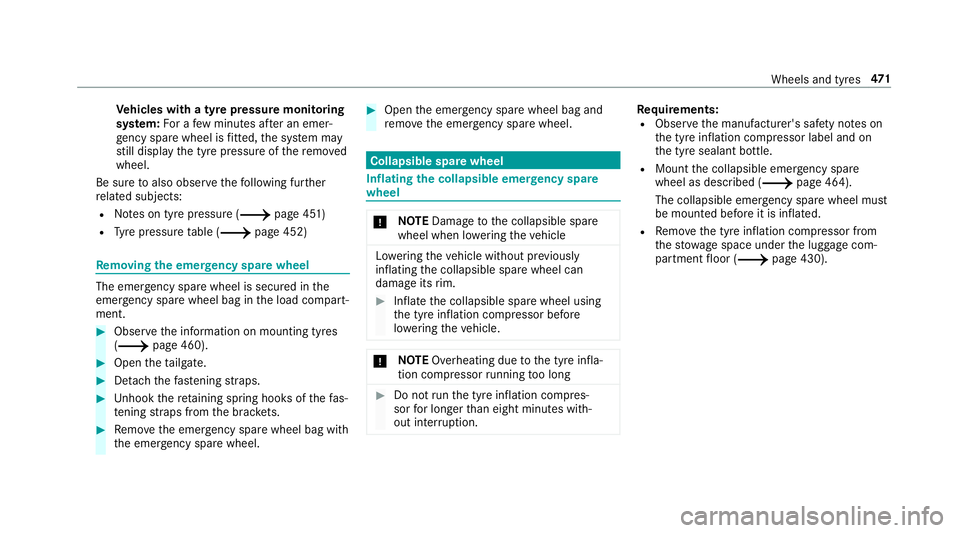
moving the eme rgency spa rewheel The eme
rgency spare wheel is secured in the
emer gency spa rewheel bag in the load compart‐
ment. 0007
Obser vethe information on mounting tyres
(0013 page 460). 0007
Open theta ilgate. 0007
Detach thefast ening stra ps. 0007
Unhook there taining spring hooks of thefa s‐
te ning stra ps from the brac kets. 0007
Remo vethe emer gency spa rewheel bag with
th e emer gency spa rewheel. 0007
Open the emer gency spa rewheel bag and
re mo vethe emer gency spa rewheel. Collapsible spa
rewheel Inflating
the collapsible emer gency spare
wheel 000E
NO
TEDama getothe collapsible spare
wheel when lo wering theve hicle Lo
we ring theve hicle without pr eviously
inflating the collapsible spare wheel can
damage its rim. 0007
Inflate the collapsible spare wheel using
th e tyre inflation compressor before
lo we ring theve hicle. 000E
NO
TEOverheating due tothe tyre infla‐
tion compressor running too long 0007
Do not runth e tyre inflation compres‐
sor for longer than eight minutes with‐
out inter ruption. Re
quirements:
R Obser vethe manufacturer's saf ety no tes on
th e tyre inflation compressor label and on
th e tyre sealant bottle.
R Mount the collapsible emer gency spa re
wheel as desc ribed (0013 page 464).
The collapsible emer gency spa rewheel must
be moun ted before it is inflated.
R Remo vethe tyre inflation compressor from
th estow age space under the luggage com‐
partment floor (0013 page 430). Wheels and tyres
471
Page 475 of 609
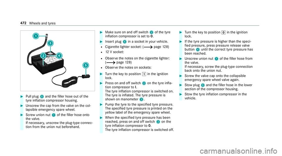
0007
Pull plug 5and thefiller hose out of the
tyre inflation compressor housing. 0007
Unscr ew the cap from theva lve on the col‐
lapsible emer gency spa rewheel. 0007
Screw union nut 1ofthefiller hose onto
th eva lve.
If necessar y,unscr ewthe plug-type connec‐
tion from the union nut beforehand. 0007
Make sure on and off switch 2ofthe tyre
inflation compressor is set to0. 0007
Insert plug 5in a soc ket in your vehicle.
R Cigar ette lighter soc ket: ( 0013 page128)
R 12V soc ket:
R Obser vethe no tes on the cigar ette lighter:
(0013 page128)
R Obse rveth e no tes on soc kets: 0007
Turn theke yto position 0047inthe ignition
loc k. 0007
Press on and off switch 2onthe tyre infla‐
tion compressor toI.
The tyre inflation compressor is switched on.
The tyre is inflated. The tyre pressure is
shown on manome ter3. 0007
Pump the tyre tothe specified tyre pressure.
The specified tyre pressure is printed on the
ye llow label of the emer gency spa rewheel. 0007
When the specified tyre pressure has been
re ached, press on and off swit ch2 onthe
tyre inflation compressor to0.
The tyre inflation compressor is switched off. 0007
Turn theke yto position 005Ainthe ignition
loc k. 0007
Ifth e tyre pressure is higher than the speci‐
fi ed pressure, press pressure release valve
bu tton 4until the cor rect tyre pressure has
been reached. 0007
Unscr ew union nut 1ofthefiller hose from
th eva lve.
If necessar y,scr ew the plug-type connection
back onto the union nut. 0007
Screw theva lve cap onto the collapsible
emer gency spa rewheel valve again. 0007
Stow plug 5and thefiller hose in the lo wer
section of the compressor housing. 0007
Stow th e tyre inflation compressor in the
ve hicle. 472
Wheels and tyres
Page 490 of 609
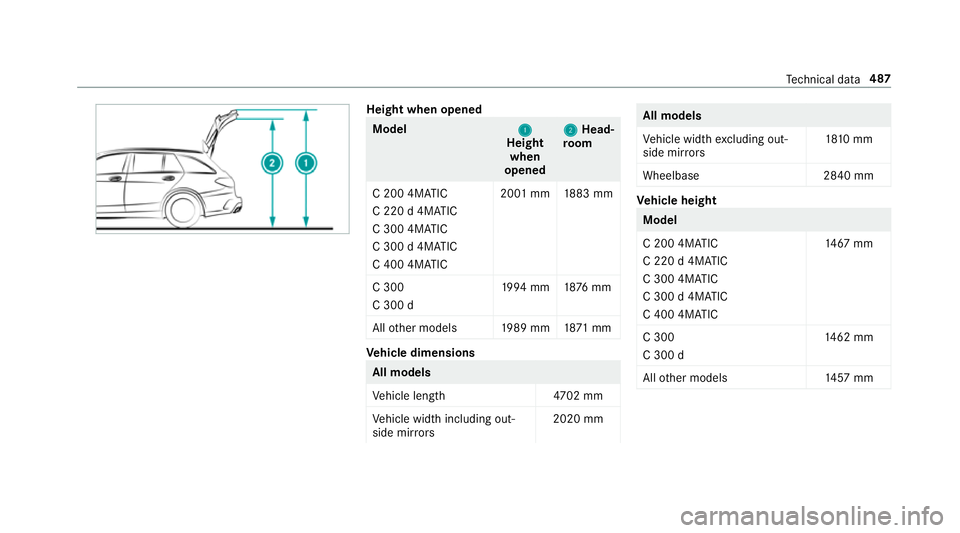
Height when opened
Model
1 1
Height
when
opened 2 2
Head‐
ro om
C 200 4MATIC
C 220 d 4MATIC
C 300 4MATIC
C 300 d 4MATIC
C 400 4MATIC 20
01 mm 1883 mm
C 300
C 300 d 19
94 mm 1876 mm
All other models 1989 mm 1871 mm Ve
hicle dimensions All models
Ve
hicle lengt h4 702 mm
Ve hicle width including out‐
side mir rors 2020 mm All models
Ve
hicle width excluding out‐
side mir rors 18
10 mm
Wheelbase 2840 mm Ve
hicle height Model
C 200 4MATIC
C 220 d 4MATIC
C 300 4MATIC
C 300 d 4MATIC
C 400 4MATIC
14 67
mm
C 300
C 300 d 14
62 mm
All other models 1457 mm Te
ch nical da ta487
Page 499 of 609
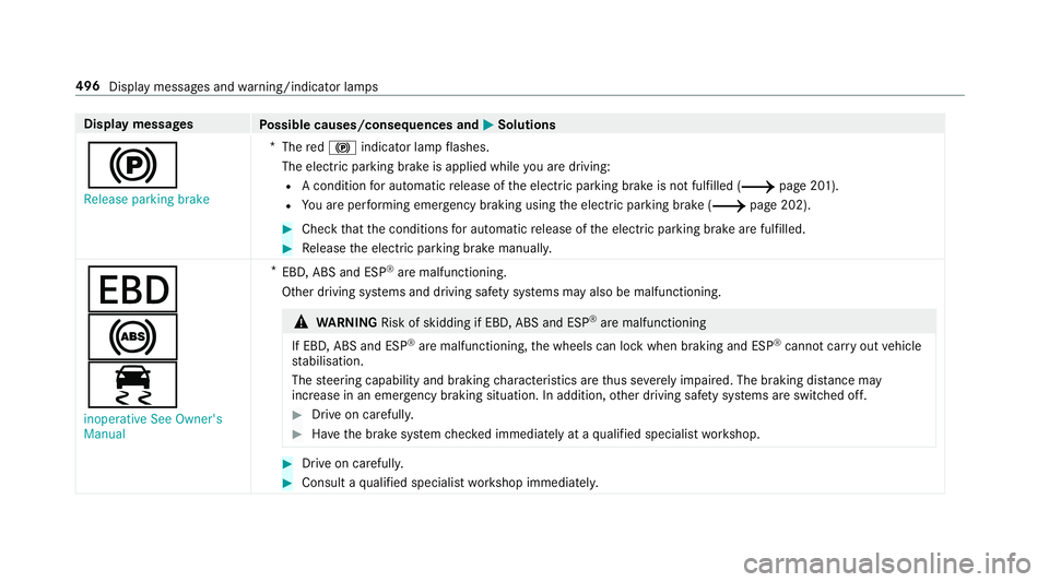
Display messages
Possible causes/consequences and 0050
0050Solutions
0024 Release parking brake *
The red0024 indicator lamp flashes.
The electric parking brake is applied while you are driving:
R A condition for auto matic release of the electric parking brake is not fulfilled (0013 page 201).
R You are per form ing emer gency braking using the electric parking brake (0013 page 202). 0007
Check that the conditions for auto matic release of the electric parking brake are fulfilled. 0007
Release the electric parking brake manually.
007A
0025
00E5
inoperative See Owner's
Manual *
EBD, ABS and ESP ®
are malfunctioning.
Other driving sy stems and driving saf ety sy stems may also be malfunctioning. 000A
WARNING Risk of skidding if EBD, ABS and ESP ®
are malfunctioning
If EBD, ABS and ESP ®
are malfunctioning, the wheels can lock when braking and ESP ®
cann otcar ryout vehicle
st abilisation.
The steering capability and braking characteristics are thus se verely impaired. The br aking distance may
increase in an eme rgency braking situation. In addition, other driving saf ety sy stems are switched off. 0007
Drive on carefull y. 0007
Have the brake sy stem checked immediately at a qualified specialist workshop. 0007
Drive on carefully. 0007
Consult a qualified specialist workshop immediatel y.496
Display messages and warning/indicator lamps
Page 501 of 609
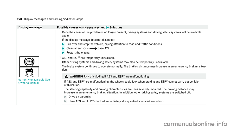
Display messages
Possible causes/consequences and 0050
0050Solutions
Once the cause of the problem is no longer present, driving sy stems and driving saf ety sy stems will be available
again.
If th e display message does not disappear: 0007
Pull over and stop theve hicle, paying attention toroad and traf fic conditions. 0007
Clean all senso rs (0013 page 422). 0007
Restart the engine.
0025
00E5
currently unavailable See
Owner's Manual *
ABS and ESP ®
are temp orarily una vailable.
Other driving sy stems and driving saf ety sy stems may also be temp orarily una vailable.
The brake sy stem continues tooperate normally. The braking dis tance may increase in an emergency braking situa‐
tion. 000A
WARNING Risk of skidding if ABS and ESP ®
are malfunctioning
If ABS and ESP ®
are malfunctioning, the wheels could lock when braking and ESP ®
cann otcar ryout vehicle
st abilisation.
The steering capability and braking characteristics are thus se verely impaired. The br aking distance may
increase in an emergency braking situation. In addition, other driving saf ety sy stems are switched off. 0007
Drive on carefull y. 0007
Have ABS and ESP ®
ch ecked immediately at a qualified specialist workshop. 498
Display messages and warning/indicator lamps
Page 502 of 609
Display messages
Possible causes/consequences and 0050
0050Solutions 0007
Carefully drive on a suitable stre tch of road, making slight steering mo vements at a speed abo ve30 km/h. 0007
Ifth e display message does not disappear, consult a qualified specialist workshop immediately. Drive carefully.
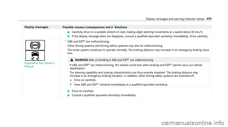
0025
00E5
inoperative See Owner's
Manual *
ABS and ESP ®
are malfunctioning.
Other driving sy stems and driving saf ety sy stems may also be malfunctioning.
The brake sy stem continues tooperate normally. The braking dis tance may increase in an emergency braking situa‐
tion. 000A
WARNING Risk of skidding if ABS and ESP ®
are malfunctioning
If ABS and ESP ®
are malfunctioning, the wheels could lock when braking and ESP ®
cann otcar ryout vehicle
st abilisation.
The steering capability and braking characteristics are thus se verely impaired. The br aking distance may
increase in an emergency braking situation. In addition, other driving saf ety sy stems are switched off. 0007
Drive on carefull y. 0007
Have ABS and ESP ®
ch ecked immediately at a qualified specialist workshop. 0007
Drive on carefully. 0007
Consult a qualified specialist workshop immediatel y. Displ
aymessa ges and warning/indicator lamps 499
Page 531 of 609
Display messages
Possible causes/consequences and 0050
0050Solutions 0007
Tocontinue your journe y,shift the transmission toposition 005Bor005E.
Only select Park (P) when
vehicle is stationary *
The transmission can only be shif tedto position 005Dwhen theve hicle is stationar y.
Risk of vehicle rolling
Driver door open and trans-
mission not in P *
The driver's door is not fully closed and the transmission is in position 005E,005Cor005B. 0007
Shift the transmission toposition 005Dwhen you park theve hicle.
Apply brake to select R *
You ha vetried toswitch totransmission position 005E. 0007
Dep ress the brake pedal. 0007
Shift the transmission toposition 005E.
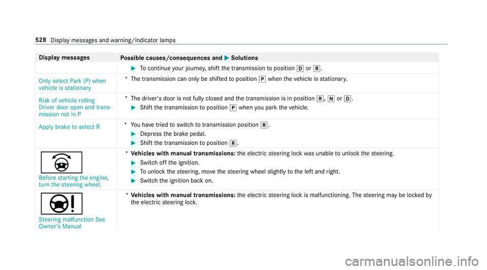
0044 Before starting the engine,
turn the steering wheel. *
Ve hicles with manual transmissions: the electric steering lock was unable tounlo ck th esteering. 0007
Switch off the ignition. 0007
Tounlo ckthesteering, mo vethesteering wheel slightly tothe left and right. 0007
Switch the ignition back on.
00CC Steering malfunction See
Owner's Manual *
Ve hicles with manual transmissions: the electric steering lock is malfunctioning. The steering may be loc kedby
th e electric steering loc k. 528
Display messages and warning/indicator lamps