2018 MERCEDES-BENZ AMG GT R-ROADSTER service indicator
[x] Cancel search: service indicatorPage 112 of 473
Overview of climate control sy
stems Note
s on climate control An interior air
filter must alw ays be used so that
th e air conditioning sy stem, pollution le vel moni‐
to ring and the air filtering function workcor‐
re ctly. Ma kesure that thefilter is ins talled cor‐
re ctly and thefilter housing in the engine com‐
partment is closed cor rectly using the cap and
alw ays tightly sealed when in operation. Use fil‐
te rs recommended and appr ovedby Mercedes-
Benz. Alw ays ha veservice workcar ried out at a
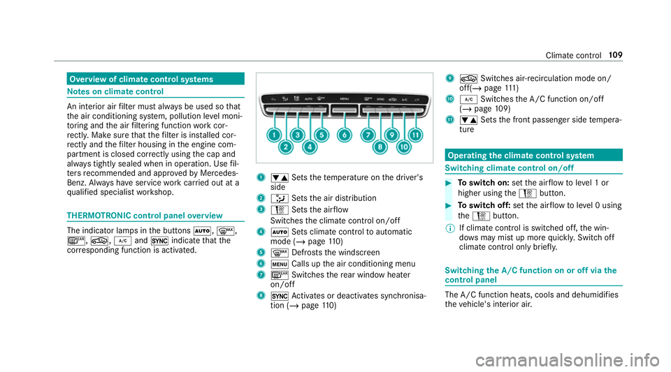
qu alified specialist workshop. THERMOTRONIC control panel
overview The indicator lamps in
the buttons Ã,¬,
¤, g,¿and0 indicate that the
cor responding function is activated. 1
w Setsthete mp erature on the driver's
side
2 _ Setsthe air distribution
3 H Setsthe air flow
Switches the climate control on/off
4 Ã Sets climate control toautomatic
mode (/ page110)
5 ¬ Defrosts the windscreen
6 t Calls up the air conditioning menu
7 ¤ Switches there ar wind owheater
on/off
8 0 Activates or deacti vates synchronisa‐
tion (/ page110) 9
g Switches air- recirculation mode on/
off(/ page 111 )
A ¿ Switches the A/C function on/off
(/ page 109)
B w Setsthe front passenger side temp era‐
ture Operating
the clima tecont rol sy stem Switching clima
tecont rol on/off #
Toswitch on: setthe air flow toleve l 1 or
higher using theH button. #
Toswitch off: setthe air flow toleve l 0 using
th eH button.
% If climate control is switched off, the win‐
do ws may mist up more quickl y.Switch off
climate control only brie fly. Switching
the A/C function on or off via the
cont rol panel The A/C function heats, cools and dehumidifies
th
eve hicle's interior air. Climate control
109
Page 337 of 473
*
NO
TEDamaging the battery thro ugh
ove rvoltage When using a battery
charge r without a maxi‐
mum charging voltage, the battery or the
ve hicle electronics may be damaged. #
Only use battery charge rs with a maxi‐
mum charging voltage of 14.8 V. &
WARNING Risk ofexplosion from hydro‐
ge nga s igniting
A battery generates hydrogen gas during the
ch arging process. If there is a short circuit or
spar ksstart toform ,th ere is a danger of the
hy drogen gas igniting. #
Make sure that the positive term inal of
th e connected battery does not come
into conta ct withvehicle parts. #
Never place me tal objects or tools on a
batter y. #
When connecting and disconnecting the
batter y,yo u must obse rveth e descri‐
bed order forth e battery clamps. #
When giving starting assis tance, al ways
make sure that you on lyconnect bat‐
te ry term inals with identical polarity. #
During starting assis tance, you must
obse rveth e described order for con‐
necting and disconnecting the jump
lead. #
Do not connect or disconnect the bat‐
te ry cla mp s while the engine is running. &
WARNING Risk ofexplosion during
ch arging process and starting assis tance
During thech arging process and starting
assis tance, the battery may release an explo‐
sive gas mixture. #
Avoid fire , naked flames, creating
spar ksand smoking. #
Make sure that there is suf ficient venti‐
lation du ring thech arging process and
during starting assis tance. #
Do not lean over a batter y. &
WARNING Risk ofexplosion from a fro‐
zen battery
A dischar ged battery may freeze at temp era‐
tures slightly abo veor below freezing point.
During starting assis tance or battery charg‐
ing, bat tery gas may be released. #
Alw aysth aw a frozen bat tery out first
before charging it or per form ing start‐
ing assis tance. If
th e indicator/warning lamps in the instrument
clus ter do not light up at low temp eratures, it is
ve ry likely that the dischar ged battery has fro‐
zen. In this case you may neither jump-s tart the
ve hicle nor charge the batter y.
The service life of a battery that has been
th awe d may be dramatically shor tened. The
st arting characteristics may be impaired, espe‐
cially at low temp eratures.
It is recommended that you ha veathaw ed bat‐
te ry checked at a qualified specialist workshop. 334
Breakdown assis tance
Page 377 of 473
Display messages
Int
roduction Note
s on display messages
Display messages appear on the multifunction
displa y.
Displ aymessa ges with graphic symbols are sim‐
plified in the Owner's Manual and may dif fer
from the symbols on the multifunction displa y.
The multifunction display sho wshigh-priority dis‐
play messages in red. Cer tain display messages
are accompanied byawa rning tone.
Please respond in accordance with the display
messages and follow the additional no tes in this
Owner's Manual.
Fo r some display messa ges, a symbol is also
shown:
R ¤ Further information R
O Hide display message
Yo u can select the desired symbol byswiping
left or right on the left-hand Touch Control.
Press the¤ symbol toshow fur ther informa‐
tion on the multifunction displa y.Press theO
symbol tohide the display message.
Yo u can hide lo w-priority display messages by
pressing the¤ button or the left-hand Touch
Control. The displ aymessa ges are then stored in
th e message memor y.
Re ctify the cause of a display message as
qu ickly as possible.
High-priority display messages cannot be hid‐
den. The multifunction display sho ws these dis‐
play messages continuously until the cause of
th e message has been rectified. Calling up
stored displ aymessages
On-boa rdcompu ter:
4 Service 5
1 message
If th ere are no display messages, No mes-
sagesappears on the multifunction displa y. #
Scroll thro ugh the display messages byswip‐
ing upwards or down wards on the left-hand
To uch Control. #
Toexitth e message memor y:press the
¤ button. 374
Displaymessa ges and warning/indicator lamps
Page 389 of 473
Display messages
Possible causes/consequences and M
MSolutions
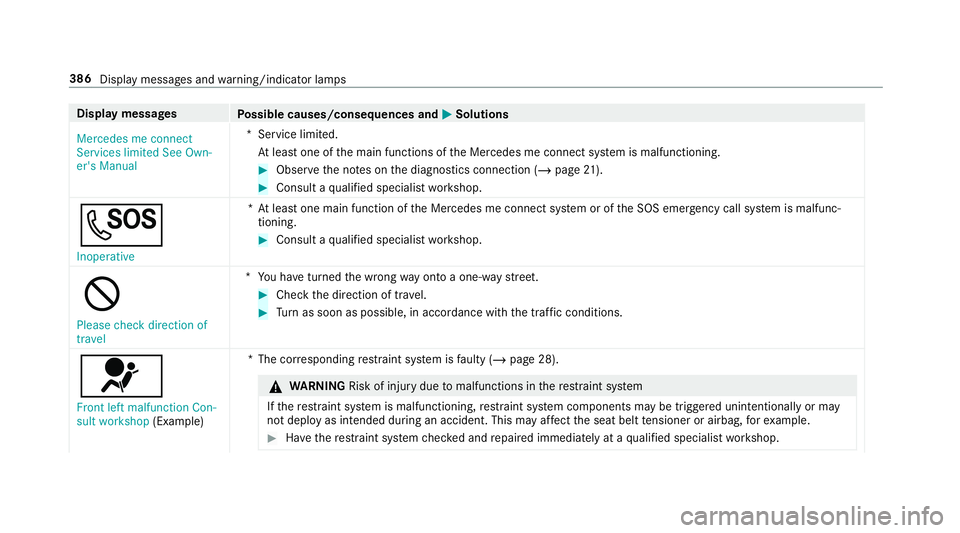
Mercedes me connect
Services limited See Own-
er's Manual *S
ervice limited.
At least one of the main functions of the Mercedes me connect sy stem is malfunctioning. #
Obser vethe no tes on the diagnostics connection (/ page21). #
Consult a qualified specialist workshop.
G Inoperative *A
t least one main function of the Mercedes me connect sy stem or of the SOS emer gency call sy stem is malfunc‐
tioning. #
Consult a qualified specialist workshop.
K Please check direction of
travel *Y
ou ha veturned the wrong way on toa one-w aystre et. #
Check the direction of tra vel. #
Turn as soon as possible, in accordance with the traf fic conditions.
6 Front left malfunction Con-
sult workshop (Example) *T
he cor responding restra int sy stem is faulty (/ page 28). &
WARNING Risk of inju rydue tomalfunctions in there stra int sy stem
If th ere stra int sy stem is malfunctioning, restra int sy stem components may be triggered unintentionally or may
not deploy as intended during an accident. This may af fect the seat belt tensioner or airbag, forex ample. #
Have there stra int sy stem checked and repaired immediately at a qualified specialist workshop. 386
Display messages and warning/indicator lamps
Page 399 of 473
Display messages
Possible causes/consequences and M
MSolutions #
Switch off the engine. #
Consult a qualified specialist workshop.
? *T
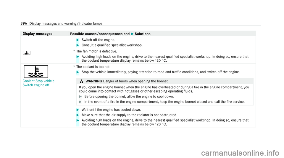
hefan mo tor is defective. #
Avoiding high loads on the engine, drive tothe nearest qualified specialist workshop. In doing so, ensure that
th e coolant temp erature display remains below 120 °C.
?
Coolant Stop vehicle
Switch engine off *T
he coolant is too hot. #
Stop theve hicle immediately, paying attention toroad and traf fic conditions, and switch off the engine. &
WARNING Danger of bu rns when opening the bonn et
If yo u open the engine bonn etwhen the engine has overheated or during a fire inthe engine compartment, you
could come into contact wi thhot gases or other escaping operating fluids. #
Before opening the bonn et, allow the engine tocool down. #
Intheeve nt of a fire inthe engine compartment, keep the engine bonn etclosed and call thefire service. #
Wait until the engine has cooled down. #
Make sure that the air supply tothera diator is not obstructed. #
Avoiding high loads on the engine, drive tothe nearest qualified specialist workshop. In doing so, ensure that
th e coolant temp erature display remains below 120 °C. 396
Displaymessa ges and warning/indicator lamps
Page 429 of 473
Wa
rning/indicator lamp
Possible causes/consequences and M
MSolutions
8 Fu elreser ve wa rning lamp The
yellow fuel reser vewarning lamp is lit while the engine is running.
The fuel supply has dropped into there ser verange. #
Refuel.
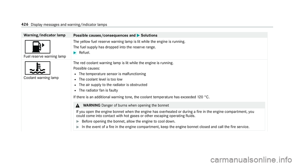
?
Coolant warning lamp The
red coolant warning lamp is lit while the engine is running.
Po ssible causes:
R The temp erature sensor is malfunctioning
R The coolant le vel is too low
R The air supply tothera diator is obstructed
R The radiator fan is faulty
If th ere is an additional warning tone, the coolant temp erature has exceeded 120 °C. &
WARNING Danger of bu rns when opening the bonn et
If yo u open the engine bonn etwhen the engine has overheated or during a fire inthe engine compartment, you
could come into contact wi thhot gases or other escaping operating fluids. #
Before opening the bonn et, allow the engine tocool down. #
Intheeve nt of a fire inthe engine compartment, keep the engine bonn etclosed and call thefire service. 426
Display messages and warning/indicator lamps
Page 435 of 473
Ad
justing the bass, mid- range and
treble
Burmes ter®
high-end 3D sur round
sound sy stem ...................................... 305
Ad justing the mid- range, treble and
bass
Burmes ter®
high-end 3D sur round
sound sy stem ...................................... 305
Ad justing the sound focus
Burmes ter®
sur round sound sy stem ... 305
Ad justing the sound optimisation
Burmes ter®
high-end 3D sur round
sound sy stem ...................................... 306
Ad justing treble, mid- range and bass
settings
Burmes ter®
high-end 3D sur round
sound sy stem ...................................... 305
Burmes ter®
sur round sound sy stem ... 304
Ae rodynamics profile .............................. 15 6
Fu nction/no tes ................................... 15 6
Re tracting/extending .......................... 15 6
Af ter-sales service centre
see ASS YST PLUS Air inlet
see Air-water duct
Air pressure see Tyre pressure
Air vents ....................................................1 11
Ad justing (front) ................................... 111
Air vents
see Air vents
Ai r-re circulation mode .............................111
Air-water duct .......................................... 314
Ke eping free ........................................3 14
Airbag ........................................................ .35
Ac tivation .............................................. 28
Fr ont airbag (driver, front passenger) ....35
Ins tallation locations ............................ .35
Knee airbag ........................................... 35
Overview ............................................... 35
PA SSENGER AIR BAG indicator lamp .... .40
Pr otection ..............................................36
Re duced pr otection ...............................37
Side impact airbag ................................ 35
Wi ndow airbag ....................................... 35 Alarm
see Panic alarm
Alarm sy stem
see ATA (anti-theft alarm sy stem)
Alternative route
see Route
Ambient lighting Setting (multimedia sy stem) ................1 02
AMG DRIVE UNIT ......................................... 15 5
St eering-wheel buttons ........................ 15 5
AMG ceramic high-per form ance com‐
posi tebrake sy stem ................................ 11 7
AMG DRIVE UNIT see AMG Performance steering wheel
AMG Performance adju stable exhaust
sy stem ...................................................... 11 9
Fu nction ............................................... 11 9
Operating ............................................. 11 9
AMG per form ance seat
Setting ................................................... 83
AMG Performance steering wheel .........155 432
Index
Page 464 of 473
Extending a Li
veTraf fic Information
subscription ........................................ 236
Issuing hazard warnings ...................... 238
Live Traf fic Information ....................... 236
Overview ............................................. 236
Re gis tering Live Traf fic Information ..... 236
Tr af fic information service volume
increase
Setting ................................................ .295
Tr af fic map
see Map
Tr af fic Sign Assist .................................. .164
Fu nction/no tes ................................... 16 4
Setting ................................................. 16 6
Sy stem limitations ...............................1 64
Tr ansfer redve hicle data
Android Auto ....................................... 263
Apple CarPl ay™ ................................... 263
Tr ansmission position display ................121
Tr anspo rting
Ve hicle ................................................ 339
Tr im element (Care) .................................321 Tr
ip
Menu (on-board computer) .................. 17 7
Tr ip computer
Displaying ............................................ 17 7
Re setting ............................................. 178
Tr ip distance ............................................ 17 7
Displ aying ............................................ 17 7
Re setting ............................................. 178
Tr ip me ter
see Trip dis tance
Tu rn signal indicator
see Turn signal lights
Tu rn signal lights ....................................... 99
Switching on/off ................................... 99
TV .............................................................. 189
Ac tivating ............................................ 297
Ad justing the brightness ..................... 303
Calling up the menu (CI+ module) .......3 03
Displ ays in theTV control menu .......... 299
Fu nction/no tes (audio language,
subtitles) ............................................. 301
Information .......................................... 295
Overview ............................................. 298
Picture settings ................................... 303 Picture settings
overview .................... 302
Setting subtitles .................................. 302
Setting the audio language .................. 301
Showing telete xt ................................. .302
Showing/hiding full screen ................. 299
Te lete xt overview ................................. 302
Vo ice commands (LINGU ATRO NIC) .....1 89
TV channel
Ac tivating/deactivating channel fix ..... 300
Channel fix .......................................... 300
Channel li stove rview .......................... 300
EPG (elect ronic programme guide) ...... 300
Overview of favo urites ........................ .300
Quick sa ve........................................... 301
Selecting from thech annel list ............ 299
Selecting from the control menu ......... 299
Selecting from thefa vo urites .............. 299
Selecting in the bac kground ................ 299
St oring .................................................3 01
Tw o phone mode
see Second telephone
Ty re inflation compressor
see TIREFIT kit Index
461