2018 MERCEDES-BENZ AMG GT R-ROADSTER brake light
[x] Cancel search: brake lightPage 10 of 473
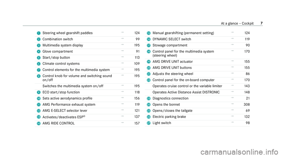
1
Steering wheel gearshift paddles →
124
2 Combination swit ch →
99
3 Multimedia sy stem display →
19 5
4 Glovecompa rtment →
91
5 Start/ stop button →
11 3
6 Climate cont rol sy stems →
109
7 Control elements forth e multimedia sy stem →
19 5
8 Control knob forvo lume and switching sound
on/off →
19 5
Switches the multimedia sy stem on/off →
19 5
9 ECO start/ stop function →
11 8
A Sets acti veaerodynamics profile →
15 6
B AMG Performance exhaust sy stem →
11 9
C AMG E-SELECT selector le ver→
121
D Activates/deacti vates ESP ®
→
137
E AMG RIDE CONTROL →
157 F
Manual gearshifting (permanent setting) →
124
G DYNA MIC SELECT switch →
11 9
H Stow age compartment →
90
I Control panel forth e multimedia sy stem
(s te ering wheel) →
17 0
J AMG DRIVE UNIT actuator →
15 5
K AMG DRIVE UNIT buttons →
15 5
L Adjusts thesteering wheel →
86
M Control panel forth e on-board computer →
17 0
Operates cruise contro l ortheva riable limiter →
14 3
Operates Active Dis tance Assi stDISTRONIC →
14 8
N Diagno stics connection →
21
O Opens the bonn et →
308
P Opens/closes theta ilgate →
69
Q Electric parking brake →
13 2
R Light switch →
98 At
aglance – Cockpit 7
Page 12 of 473
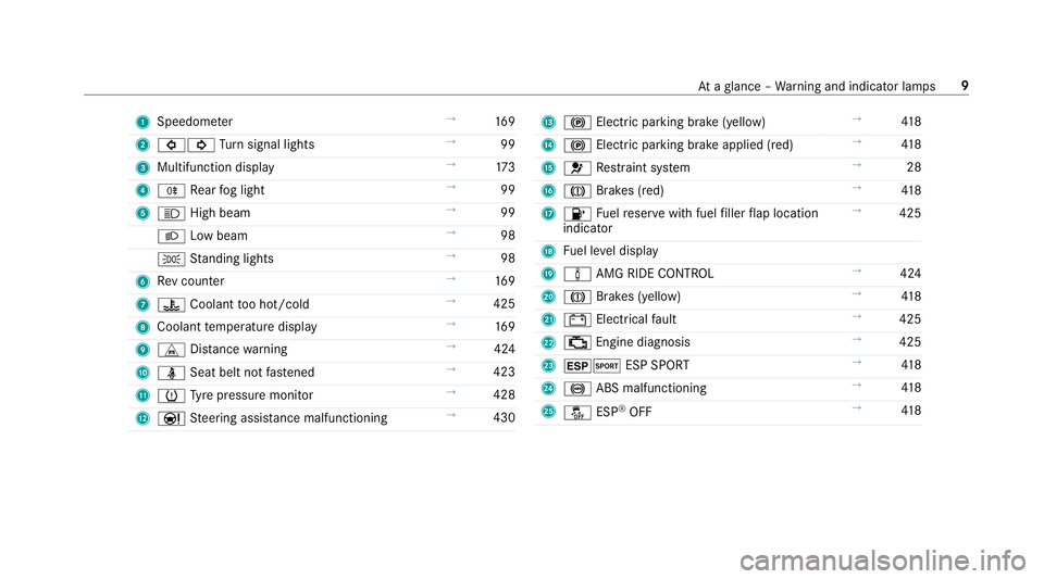
1
Speedom eter →
16 9
2 #! Turn signal lights →
99
3 Multifunction display →
173
4 R Rear fog light →
99
5 K High beam →
99
L Low beam →
98
T Standing lights →
98
6 Rev counter →
16 9
7 ? Coolant too hot/cold →
425
8 Coolant temp erature display →
16 9
9 L Distance warning →
424
A ü Seat belt not fastened →
423
B h Tyre pressure monitor →
428
C Ð Steering assis tance malfunctioning →
430 D
! Electric pa rking brake (yellow) →
41 8
E ! Electric pa rking brake applied (red) →
41 8
F 6 Restra int sy stem →
28
G J Brakes (red) →
41 8
H 8 Fuelreser vewith fuel filler flap location
indicator →
425
I Fuel le vel display
J à AMG RIDE CONTROL →
424
K J Brakes (yellow) →
41 8
L # Electrical fault →
425
M ; Engine diagnosis →
425
N ±M ESP SPORT →
41 8
O ! ABS malfunctioning →
41 8
P å ESP®
OFF →
41 8 At
aglance – Warning and indicator lamps 9
Page 27 of 473

of an accident,
rescue services can use the QR
code toquickly find the appropriate rescue card
fo ryo ur vehicle. The cur rent rescue card con‐
ta ins the most impor tant information about your
ve hicle in a compact form , e.g. thero uting of the
electric lines.
Fu rther information can be obtained at http://
www.mercedes-benz.de/qr-code. Data
storage Electronic control units
Elect
ronic control units are fitted in your vehicle.
Some of these are necessary forth e safe opera‐
tion of your vehicle, while some assist you when
driving (driver assis tance sy stems). In addition,
yo ur vehicle pr ovides com fort and enter tainment
functions, which are also made possible byelec‐
tronic control units.
Elect ronic control units contain da tamemories
which can temp orarily or permanently store
te ch nical information about theve hicle's operat‐
ing state, component loads, main tenance
re qu irements and tech nical events or faults. In
general, this information documents thest ate
of a component part, a module, a sy stem or the
sur roundings such as:
R operating status of sy stem components (e.g.
fi ll le vels, battery status, tyre pressure)
R status messages concerning theve hicle or
its individual components (e.g. number of
wheel revo lutions/speed, longitudinal accel‐
eration, lateral acceleration, display of fas‐
te ned seat belts)
R malfunctions or faults in impor tant sy stem
components (e.g. lights, brakes)
R information on events leading tovehicle
damage
R system reactions in special driving situations
(e.g. airbag deployment, inter vention of sta‐
bility control sy stems)
R ambient conditions (e.g. temp erature, rain
sensor)
In addition toprov iding the actual control unit
function, this data assists the manufacturer in
de tecting and rectifying faults and optimising
ve hicle functions. The majority of this data is te
mp orary and is only processed in theve hicle
itself. Only a small portion of the data is stored
in theeve nt or fault memor y.
When your vehicle is serviced, tech nical da ta
from theve hicle can be read out byservice net‐
wo rkemplo yees (e.g. workshops, manufactur‐
ers) or third parties (e.g. breakdown services).
Services include repair services, maintenance
processes, warranty claims and quality assur‐
ance measures, forex ample. The read out is per‐
fo rm ed via the legally prescribed port forthe
diagnostics connection in theve hicle. The
re spective service network locations or third
parties collect, process and use the data. They
document tech nical statuses of theve hicle,
assist in finding faults and impr oving quality and
are transmitted tothe manufacturer, if neces‐
sar y.Fu rthermore, the manufacturer is subject
to product liability. Forth is, the manufacturer
requ irestech nical da tafrom vehicles.
Fa ult memories in theve hicle can be reset by a
service outlet as part of repair or maintenance
wo rk. 24
General no tes
Page 103 of 473
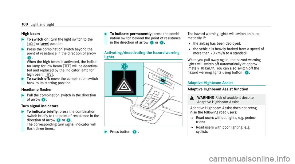
High beam
#
Toswitch on: turnthe light switch tothe
L orà position. #
Press the combination switch be yond the
point of resis tance in the direction of ar row
1 .
When the high beam is activated, the indica‐
to r lamp for low beam Lwill be deactiva‐
te d and replaced bythe indicator lamp for
high beam K. #
Toswitch off: movethe combination switch
back toits starting position.
Headla mpflasher #
Pull the combination switch in the direction
of ar row3.
Tu rn signal indicators #
Toindicate briefl y:press the combination
switch briefly tothe point of resis tance in the
direction of ar row2or4.
The cor responding turn signal indicator will
fl ash thre e times. #
Toindicate permanentl y:press the combi‐
nation switch be yond the point of resis tance
in the direction of ar row2or4. Ac
tivating/deactivating the hazard warning
lights #
Press button 1. The hazard
warning lights will switch on auto‐
matically if:
R the airbag has been deplo yed.
R theve hicle is heavily braked from a speed of
more than 70 km/h toast andstill.
When you pull away again, the hazard warning
lights will switch off automatically at appr ox‐
imately 10km/h. You can also swit choff the
hazard warning lights using button 1. Ad
aptive Highbeam Assist Ad
aptive Highbeam Assist function &
WARNING Risk of accident despi te
Ad aptive Highbeam Assist
Ad aptive Highbeam Assist does not recog‐
nise thefo llowing road users:
R Road users without lights, e.g. pedes‐
trians
R Road users with poor lighting, e.g.
cyclists 100
Light and sight
Page 117 of 473
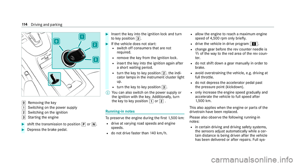
g
Removing thekey
1 Switching on the po wer supp ly
2 Switching on the ignition
3 Starting the engine #
shift the transmission toposition jori. #
Depress the brake pedal. #
Insert theke y in tothe ignition lock and turn
to key position 3. #
Ifth eve hicle does not star t:
R switch off consumers that are not
requ ired.
R remo vetheke y from the ignition loc k.
R inse rttheke y in tothe ignition again af ter
a short waiting period.
R turn theke yto key position 2.the indi‐
cator lamps in the instrument clus ter light
up.
R turn theke yto key position 3.
% You can also swit chon the po wer supp lyor
th e ignition with thekey. Additionall y,turn
th eke yto key position 1or2 . Ru
nning-in no tes To
preser vethe engine during thefirs t1, 500 km:
R drive at varying road speeds and engine
speeds.
R do not drive fasterthan 140 km/h. R
allow the engine toreach a maximum engine
speed of 4,500 rpm on ly brie fly.
R drive theve hicle in drive program A.
R change gear before there v counter needle is
Ô ofthewa yto there d area of there v coun‐
te r.
R do not shift down a gear manually in order to
brake.
R avoidove rstraining theve hicle, e.g. driving at
full thro ttle.
R do not depress the accelera tor pedal past
th e pressure point (kickdown).
R only increase the engine speed gradually and
accelera tetheve hicle tofull speed af ter
1, 500 km.
This also applies when the engine or parts of the
driv etra in ha vebeen replaced.
Please also obser vethefo llowing running-in
no tes:
R in cer tain driving and driving saf ety sy stems,
th e sensors adjust automatically while a cer‐
ta in dis tance is being driven af terth eve hicle
has been delivered or af terre pairs. Full sys‐ 11 4
Driving and pa rking
Page 119 of 473
#
Do not shi ftdown on slippery road sur‐
fa ces toinc rease the engine braking
ef fect. &
DANG ER Risk of fata l injuries due topoi‐
sonous exhaust gases
If th eta ilpipe is bloc ked or suf ficient ventila‐
tion is not possible, poisonous exhaust gases
such as carbon monoxide may enter theve hi‐
cle. This is the case, forex ample, if theve hi‐
cle is stuck in sn ow. #
When the engine or thest ationary
heater are running, keep theta ilpipe
and the area around theve hicle clear of
sno w. #
Open a window on the side of theve hi‐
cle facing the wind toensure an ade‐
qu ate supply of fresh air. &
WARNING Risk of accident due tothe
brake sy stem overheating
If yo u lea veyour foot on the brake pedal
when driving, the brake sy stem may over‐
heat.
This increases the braking dis tance and the
brake sy stem may evenfa il. #
Never use the brake pedal as a foot re st. #
Do not depress the brake pedal and the
accelerator pedal at the same time
while driving. *
NO
TECausing wearto the brake linings
by permanently depressing the brake
pedal #
Do not permanently depress the brake
pedal while driving. #
Touse braking ef fect of the engine,
shift toa lo werge ar in good time. *
NO
TEDama getothe driv etra in and
engine when pulling away #
Do not warm upthe engine while the
ve hicle is stationar y.Pull away immedi‐
atel y. #
Avoid high engine speeds and driving at
full thro ttle until the engine has reached
its operating temp erature. *
NO
TEDama getothe catalytic con verter
due tonon-combu sted fuel The engine is not
running smo othly and is
misfiring.
Non-combus ted fuel may get into the cata‐
lytic con verter. #
Only depress the accelera tor pedal
slightl y. #
Have the cause rectified immediately at
a qu alified specialist workshop. 11 6
Driving and pa rking
Page 139 of 473
and do not
relie ve you of your responsibility per‐
ta ining toroad traf fic la w.Pay attention tothe
traf fic conditions at all times and inter vene
when necessa ry. Be aware of the limitations
re ga rding the safe use of these sy stems. Information about
radar senso rs Some driving and driving sa
fety sy stems use
ra dar sensors tomonitor the area in front of,
behind or next totheve hicle (depending on the
ve hicle's equipment).
Depending on theve hicle's equipment, thera dar
sensors are integrated behind the bumpers
and/or behind the Mercedes star. Keep these
parts free of dirt, ice and slush (/ page 320).
The sensors must not be co vered, forex ample
by cycle rack s, overhanging loads, sticke rs,fo il
or foils toprotect against stone chipping. In the
eve nt of dama getothe bumpers or radiator
grille, or following a collision impacting the
bumpers or radiator grille, ha vethe function of
th era dar sensors checked at a qualified special‐
ist workshop. The driver assis tance sy stem may
no longer workproperly. Overview of driving sy
stems and driving
saf ety sy stems In
this section, you will find information about
th efo llowing driving sy stems and driving saf ety
sy stems:
R ABS (A nti-lock Braking System)
(/ page 136)
R Active Dis tance Assi stDISTRONIC
(/ page 147)
R Adaptive Brake Lights (/ page142)
R AMG RIDE CONTROL (/ page157)
R Active Brake Assi st
R Lane Keeping Assist (/ page167)
R ATTENTION ASSIST (/ page163)
R BAS (Bra keAssist System) (/ page137)
R Hill Start Assist (/ page151)
R EBD ( Electronic Brakeforce Distribution)
(/ page 140)
R ESP ®
(Electronic Stability Program)
(/ page 137)
R HOLD fu nction (/ page 151) R
Limi ter (/ page144)
R Parking Assist PARKTRONIC (/ page158)
R Front and reve rsing camera (/ page161)
R RACE START (/ page 153)
R Cruise control (/ page143)
R Blind Spot Assi st (/ page 166)
R Traf fic Sign Assi st (/ page 164) Fu
nction of ABS (Anti-lock Braking Sy stem) ABS
regulates the brake pressure in critical driv‐
ing situations:
R During braking, e.g. at full brake application
or insuf ficient tyre traction, the wheels are
pr eve nted from lo cking.
R Vehicle steerability while braking is ensured.
If ABS inter venes when braking, you will feel a
pulsing in the brake pedal. The pulsating brake
pedal can be an indication of hazardous road
conditions and can ser veas a reminder totake
ex tra care while driving. 13 6
Driving and pa rking
Page 140 of 473
Sy
stem limitations
R ABS is active from speeds of appr ox.
8 km/h.
R ABS may be impai red or may not function if a
malfunction has occur red and theye l‐
low ! ABSwarning lamp lights up contin‐
uously in the instrument clus ter af terthe
engine is star ted. Fu
nction of BAS (Brake Assist Sy stem) &
WARNING Risk of an accident caused by
a malfunction in BAS (Brake Assi stSys‐
te m)
If BA S is malfunctioning, the braking dis tance
in an emergency braking situation is
increased. #
Dep ress the brake pedal with full force
in emer gency braking situations. ABS
pr eve nts the wheels from locking. BA
S suppo rts yo ur eme rgency braking situation
with additional brake forc e. If
yo u depress the brake pedal quickl y,BA S is
acti vated:
R BAS au tomatical lyboosts the brake pres‐
sure.
R BAS can sho rten the braking dis tance.
R ABS pr events the wheels from locking.
The brakes will function as usual once you
re lease the brake pedal. BAS is deactivated. Fu
nction of ESP ®
(Electronic Stability Pro‐
gr am) &
WARNING Risk of skidding if ESP ®
is
malfunctioning
If ESP ®
is malfunctioning, ESP ®
cannot car ry
out vehicle stabilisation. In addition, other
driving saf ety sy stems are switched off. #
Drive on carefull y. #
Have ESP ®
ch ecked at a qualified spe‐
cialist workshop. Yo
u can select between thefo llowing modes of
ESP ®
:
R ESP ®
on
R SPO RThandling mode on
R ESP ®
off
Characteristics when ESP ®
is activated
ESP ®
monitors and impr oves driving stability and
traction, particular lyin thefo llowing situations:
R When pulling away on wet or slippe rycar ria‐
ge wa ys.
R When braking.
R Instro ng sidewinds when you are driving
fast erthan 70 km/h.
ESP ®
can stabilise theve hicle byinter vening in
th efo llowing ways:
R One or more wheels are braked.
R The engine output is adap ted according to
th e situation.
ESP ®
is activated everytime the engine is star‐
te d, rega rdless of whe ther ESP ®
wa s in SPORT Driving and parking
137