2018 MERCEDES-BENZ AMG GT R-ROADSTER service
[x] Cancel search: servicePage 317 of 473
#
Allow the engine tocool down and only
to uch co mponent parts described in
th efo llowing. &
WARNING Danger of bu rns when open‐
ing the bonn et
If yo u open the engine bonn etwhen the
engine has overheated or during a fire inthe
engine compartment, you could come into
contact with hot gases or other escaping
operating fluids. #
Before opening the bonn et, allow the
engine tocool down. #
Intheeve nt of a fire inthe engine com‐
partment, keep the engine bonn et
closed and call thefire service. &
WARNING ‑ Risk of fire and injury due to
windscreen washer concentrate
Wi ndsc reen washer concentrate is highly
fl ammable. It could ignite if it comes into
con tact wi thhot engine component parts or
th eex haust sy stem. #
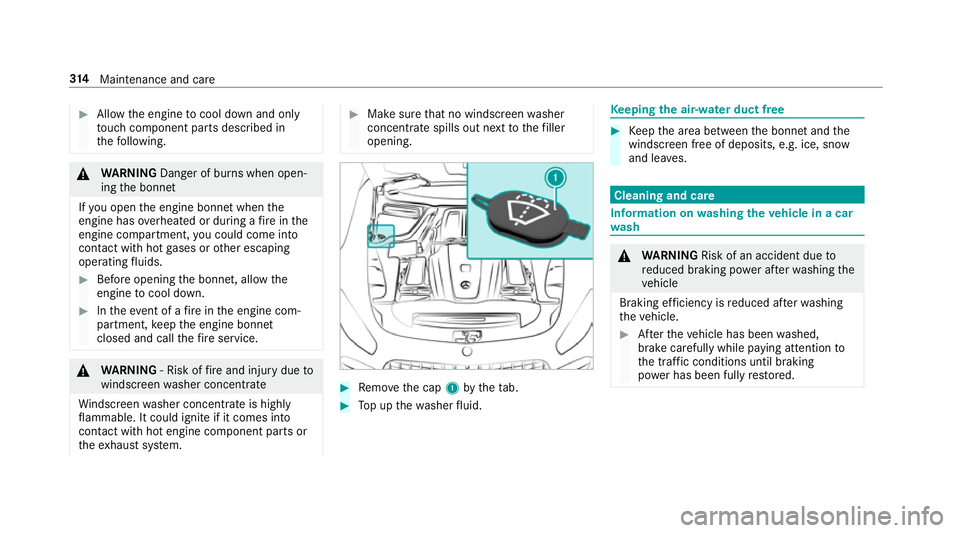
Make sure that no windsc reen washer
concentrate spills out next tothefiller
opening. #
Remo vethe cap 1bytheta b. #
Top up thewa sher fluid. Ke
eping the air-water duct free #
Keep the area between the bonn etand the
windscreen free of deposits, e.g. ice, sn ow
and lea ves. Cleaning and care
Information on
washing theve hicle in a car
wa sh &
WARNING Risk of an accident due to
re duced braking po wer af terwa shing the
ve hicle
Braking ef ficiency is reduced af terwa shing
th eve hicle. #
Afterth eve hicle has been washed,
brake carefully while paying attention to
th e traf fic conditions until braking
po we r has been fully restored. 314
Maintenance and care
Page 322 of 473
Obser
vethefo llowing information: Cleaning
Avoiding dama getothe decorative foil
R For cleaning, use plenty of water and a mild cleaning agent without
additives or abrasive substances, e.g. a car sha mpoo appr ovedfor
Mercedes-Benz.
R Remo vedirt immediately, where possible, whilst avoiding rubbing
to o hard. There is otherwise a risk of damaging the decorative foil
ir re parably.
R Ifth ere is dirt on thefinish or if the decorative foil is dull: use the
Pa int Cleaner recommended and appr ovedfo r Mercedes-Benz.
R Insect remains: soak with insect remo ver and rinse off the treated
areas af terw ards.
R Bird droppings: soak with water and rinse off af terw ards.
R Toprev ent waterst ains, dry a foil-wrapped vehicle with a soft,
absorbent clo thafte reve rycar wash. R
The service life and colouring of decorative foils are impaired by:
- sunlight
- temp erature, e.g. hot air blo wer
- weather conditions
- stone chippings and dirt
- chemical cleaning agents
- oily products
R Do not use polish on matt decorative foil. Po lishing will ha vethe ef fect of
shining thefo il-wrapped sur face.
R Do not treat matt or stru ctured deco rative foils with wax.Pe rm anent
st ains may occur. Sc
ratches, cor rosive deposits, areas af fected by
cor rosion and damage caused byincor rect care
cannot al ways be comple tely repaired. In such
cases, visit a qualified specialist workshop.
Yo u can obtain more information on care and
cleaning products from the manufacturer. In
the case of foil-wrapped sur faces, optical dif‐
fe re nces may occur between the sur faces that
we renot pr otected bya decorative foil af ter
re moving a decorative foil. %
Have wo rkor repairs todecorative foils car‐
ri ed out at a qualified specialist workshop,
e.g. in a Mercedes-Benz service centre. Maintenance and care
319
Page 330 of 473
Ve
hicles with tyre pressure monitoring sys‐
te m: MOExtended tyres may only be used in
conjunction wi than activated tyre pressure mon‐
itoring sy stem.
If a pressure loss warning message appears in
th e multifunction displa y,proceed as follo ws:
R Check the tyre for dama ge.
R If driving on, obser vethefo llowing no tes.
Driving distance possible in emer gency
mode af ter the pressure loss warning: Load condition Driving distance pos‐
sible in emergency
mode
Pa rtially laden 80 km
Fu lly laden 30 kmThe driving dis
tance possible in emergency
mode may vary depending on the driving style.
Obser vethe maximum permissible speed of
80 km/h. If a tyre has gone
flat and cannot be replaced
with an MOEx tended tyre, you can use a stand‐
ard tyre as a temp orary measure. TIREFIT kit
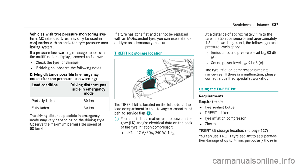
storage location The TIREFIT kit is located on
the left side of the
load compartment in thestow age compartment
behind service flap 1.
% You can find information on the po wer cate‐
gory (LK) and/or electrical data on the back
of the tyre inflation compressor:
R LK3 – 12V/20A, 240W, 1kg At
a dis tance of appr oximately 1 m tothe
tyre inflation compressor and appr oximately
1. 6 m abo vethe ground, thefo llowing sound
pressure le vels apply:
R Emission sound pressure le vel L
PA 83 dB
(A)
R Sound po wer le vel L
WA 91
dB (A)
The tyre inflation compressor is mainte‐
nance-free. If there is a malfunction, please
conta ct aqualified specialist workshop. Using
the TIREFIT kit Re
quirements:
Re quired tools:
R Tyre sealant bottle
R TIREFIT sticker
R Tyre inflation compressor
R Gloves
TIREFIT kit storage location: (/ page 327)
Yo u can use TIREFIT tyre sealant toseal per fora‐
tion dama geof up to4 mm, particularly those in Breakdown assis
tance 327
Page 333 of 473
If, af
terte n minutes, a tyre pressure of
200 kPa (2.0 bar/29 psi) has not been ach‐
ie ve d: #
Switch off the tyre inflation compressor. #
Unscr ew thefilling hose from theva lve of the
defective tyre.
Please no tethat tyre sealant may leak out when
unscr ewing thefilling hose. #
Drive forw ards or reve rseve ry slowly for
appr oximately 10m. #
Pump up the tyre again.
Af ter a maximum of ten minu testh e tyre
pressure must be at least 200 kPa (2.0 bar/
29 psi). &
WARNING Risk of accident due tothe
specified tyre pressure not being ach‐
ie ved
If th e specified tyre pressure is not achie ved
af te rth e specified time, the tyre is too badly
damaged. The tyre sealant cannot repair the
tyre in this ins tance. Dama
ged tyres and a tyre pressure that is
to o low can significantly impair braking and
handling characteristics. #
Do not drive on. #
Consult a qualified specialist workshop. If, af
terte n minutes, a tyre pressure of
200 kPa (2.0 bar/29 psi) has been achie ved: #
Switch off the tyre inflation compressor. #
Unscr ew thefilling hose from theva lve of the
defective tyre. &
WARNING Risk of accident from driving
wi th sealed tyres
A tyre temp orarily sealed with tyre sealant
impairs driving characteristics and is not
suitable for higher speeds. #
Adapt your driving style according lyand
drive carefull y. #
Do not exceed the maximum speed
limit with a tyre that has been repaired
using tyre sealant. #
Obser vethe maximum permissible speed for
a tyre sealed with tyre sealant 80 km/h. #
Affix th e upper section of the TIREFIT sticker
to the instrument clus ter in a location where
it will be easi lyseen bythe driver.
* NO
TEStaining from leaking tyre sealant Af
ter use, excess tyre sealant may leak out
from thefilling hose. #
Therefore, place thefilling hose in the
plastic bag that con tained the TIREFIT
kit. +
ENVIRONMEN
TALNO TEEnvironmental
pollution caused byenvironmen tally ir re‐
sponsible disposal Ty
re sealant contains polluta nts. #
Have the tyre sealant bottle disposed of
professionall y,e.g. at a Mercedes-Benz
Service Centre. #
Stow th e tyre sealant bottle, the tyre inflation
compressor and thewa rning triangle. 330
Breakdown assis tance
Page 334 of 473
#
Pull away immediatel y. #
Stop driving af ter appro ximately ten minu tes
and check the tyre pressure using the tyre
inflation compressor.
The tyre pressure must now be at least
13 0 kPa (1.3 bar/19 psi). &
WARNING Risk of accident due tothe
specified tyre pressure not being ach‐
ie ved
If th e specified tyre pressure is not achie ved
af te r a brief drive, the tyre is too badly dam‐
aged. The tyre sealant cannot repair the tyre
in this ins tance.
Dama ged tyres and a tyre pressure that is
to o low can significantly impair braking and
handling characteristics. #
Do not drive on. #
Consult a qualified specialist workshop. Countries
that ha veMercedes-Benz
Service24h: you will find a sticke r with thete le‐
phone number, e.g. on the B‑pillar on the driver's
side. #
Cor rect the tyre pressure if it is still at least
13 0 kPa (1.3 bar/19 psi). See the tyre pres‐
sure table on the fuel filler flap forva lues. #
Toincrease the ty repressure: switch on
th e tyre inflation compressor. #
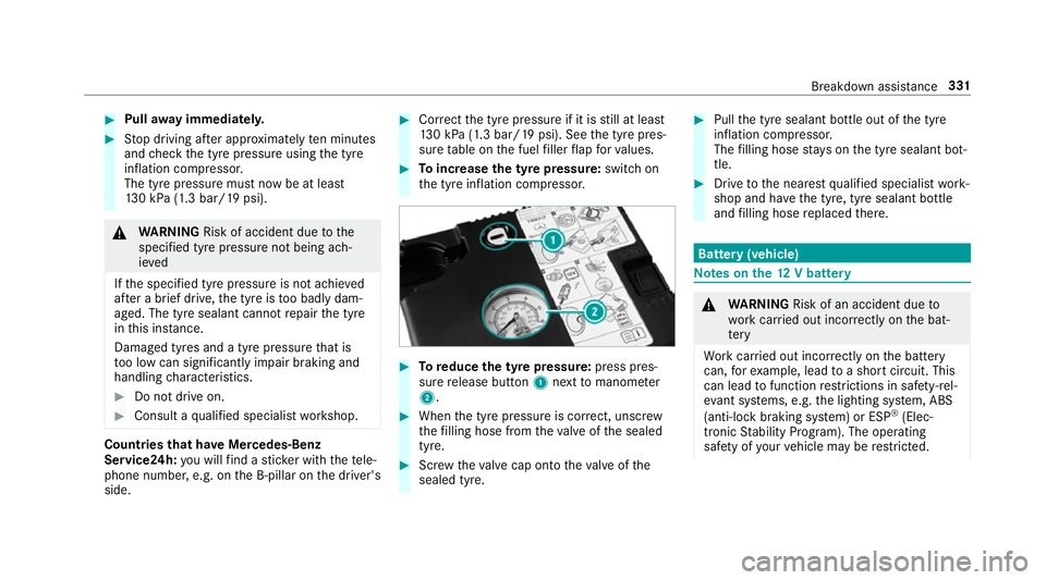
Toreduce the tyre pressure: press pres‐
su re re lease button 1next tomanome ter
2 . #
When the tyre pressure is cor rect, unscr ew
th efilling hose from theva lve of the sealed
tyre. #
Screw theva lve cap onto theva lve of the
sealed tyre. #
Pull the tyre sealant bottle out of the tyre
inflation compressor.
The filling hose stay s on the tyre sealant bot‐
tle. #
Drive tothe nearest qualified specialist work‐
shop and ha vethe tyre, tyre sealant bottle
and filling hose replaced there. Batte
ry(vehicle) Note
s onthe12 V battery &
WARNING Risk of an accident due to
wo rkcar ried out incor rectly on the bat‐
te ry
Wo rkcar ried out incor rectly on the battery
can, forex ample, lead toa short circuit. This
can lead tofunction restrictions in saf ety-re l‐
eva nt sy stems, e.g. the lighting sy stem, ABS
(anti-lock braking sy stem) or ESP ®
(Elec‐
tronic Stability Prog ram). The operating
saf ety of your vehicle may be restricted. Breakdown assis
tance 331
Page 337 of 473
*
NO
TEDamaging the battery thro ugh
ove rvoltage When using a battery
charge r without a maxi‐
mum charging voltage, the battery or the
ve hicle electronics may be damaged. #
Only use battery charge rs with a maxi‐
mum charging voltage of 14.8 V. &
WARNING Risk ofexplosion from hydro‐
ge nga s igniting
A battery generates hydrogen gas during the
ch arging process. If there is a short circuit or
spar ksstart toform ,th ere is a danger of the
hy drogen gas igniting. #
Make sure that the positive term inal of
th e connected battery does not come
into conta ct withvehicle parts. #
Never place me tal objects or tools on a
batter y. #
When connecting and disconnecting the
batter y,yo u must obse rveth e descri‐
bed order forth e battery clamps. #
When giving starting assis tance, al ways
make sure that you on lyconnect bat‐
te ry term inals with identical polarity. #
During starting assis tance, you must
obse rveth e described order for con‐
necting and disconnecting the jump
lead. #
Do not connect or disconnect the bat‐
te ry cla mp s while the engine is running. &
WARNING Risk ofexplosion during
ch arging process and starting assis tance
During thech arging process and starting
assis tance, the battery may release an explo‐
sive gas mixture. #
Avoid fire , naked flames, creating
spar ksand smoking. #
Make sure that there is suf ficient venti‐
lation du ring thech arging process and
during starting assis tance. #
Do not lean over a batter y. &
WARNING Risk ofexplosion from a fro‐
zen battery
A dischar ged battery may freeze at temp era‐
tures slightly abo veor below freezing point.
During starting assis tance or battery charg‐
ing, bat tery gas may be released. #
Alw aysth aw a frozen bat tery out first
before charging it or per form ing start‐
ing assis tance. If
th e indicator/warning lamps in the instrument
clus ter do not light up at low temp eratures, it is
ve ry likely that the dischar ged battery has fro‐
zen. In this case you may neither jump-s tart the
ve hicle nor charge the batter y.
The service life of a battery that has been
th awe d may be dramatically shor tened. The
st arting characteristics may be impaired, espe‐
cially at low temp eratures.
It is recommended that you ha veathaw ed bat‐
te ry checked at a qualified specialist workshop. 334
Breakdown assis tance
Page 339 of 473
#
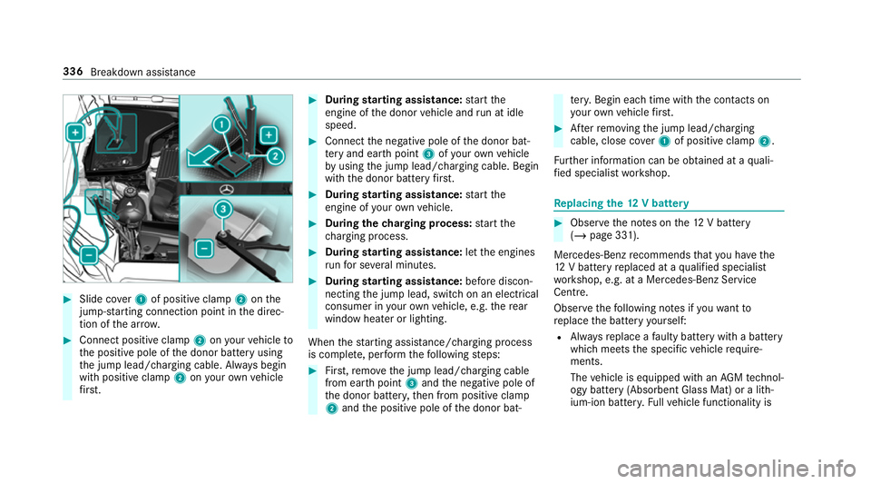
Slide co ver1 of positive clamp 2onthe
jump-s tarting connection point in the direc‐
tion of the ar row. #
Connect positive clamp 2onyour vehicle to
th e positive pole of the donor battery using
th e jump lead/charging cable. Alw ays begin
with positive clamp 2onyour ow nve hicle
fi rs t. #
During starting assi stance: start the
engine of the donor vehicle and run at idle
speed. #
Connect the negative pole of the donor bat‐
te ry and ear thpoint 3ofyour ow nve hicle
by using the jump lead/charging cable. Begin
with the donor battery firs t. #
During starting assi stance: start the
engine of your ow nve hicle. #
During thech arging process: start the
ch arging process. #
During starting assi stance: letthe engines
ru nfo r se veral minutes. #
During starting assi stance: before discon‐
necting the jump lead, switch on an electrical
consumer in your ow nve hicle, e.g. there ar
wind owheater or lighting.
When thest arting assis tance/charging process
is compl ete, per form thefo llowing steps: #
First,re mo vethe jump lead/charging cable
from ear thpoint 3and the negative pole of
th e donor batter y,then from positive clamp
2 and the positive pole of the donor bat‐ te
ry. Begin ea chtime wi th the conta cts on
yo ur ow nve hicle firs t. #
Afterre moving the jump lead/charging
cable, close co ver1 of positive clamp 2.
Fu rther information can be obtained at a quali‐
fi ed specialist workshop. Re
placing the 12V battery #
Obser vethe no tes on the12 V battery
(/ page 331).
Mercedes-Benz recommends that you ha vethe
12 V battery replaced at a qualified specialist
wo rkshop, e.g. at a Mercedes-Benz Service
Centre.
Obser vethefo llowing no tes if youwa ntto
re place the battery yourself:
R Alw aysre place a faulty bat tery with a battery
which meets the specific vehicle require‐
ments.
The vehicle is equipped with an AGMtech nol‐
ogy battery (Absorbent Glass Mat) or a li th‐
ium-ion batter y.Fu llve hicle functionality is 336
Breakdown assis tance
Page 343 of 473
As a
result, when transporting vehicles with
th eAd aptive Damping Sy stem PLUS, the
ve hicle/trailer combination may start toskid.
Consequentl y,yo u could lose cont rol of your
ve hicle. #
When transporting, ensure that:
R theve hicle has been loaded onto
th e transpor ter cor rectly
R theve hicle is secured at all four
wheels with suitable tensioning
st ra ps
R the maximum permissible speed of
60 km/h is not exceeded when
transporting *
NO
TEDama getotheve hicle from secur‐
ing it incor rectly #
After loading, theve hicle must be
secured on all four wheels. Otherwise,
th eve hicle could be damaged. #
A minimum dis tance of 20 cm up wards
and 10cm down wards must be kept to
th e transport platform. #
Secure theve hicle on all four wheels af ter
loading. #
Make sure that the front and rear axles come
to rest on the same transpor tation vehicle.
* NO
TEDama getothe driv etra in due to
incor rect positioning #
Do not position theve hicle abo vethe
connection point of the transport vehi‐
cle. To
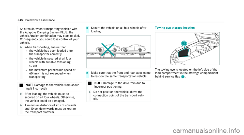
wing eyesto rage location The
towing eye is located on the left side of the
load compartment in thestow age compartment
behind service flap 1. 340
Breakdown assis tance