2018 LEXUS LS500 ignition
[x] Cancel search: ignitionPage 342 of 514

342 5-6. Using the other interior features
LS500_OM_OM50F54U_(U) 5-6.Using the other interior features
The USB charging ports are used to
supply 2.1 A of electricity at 5 V to
external devices.
The USB charging ports are for
charging only. They are not designed
for data transfer or other purposes.
Depending on the external device, it
may not charge properly. Refer to the
manual included with the device
before using a USB charging port. ■
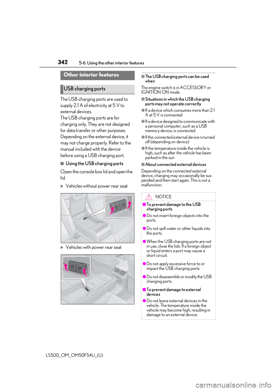
Using the USB charging ports
Open the console box lid and open the
lid.
Vehicles without power rear seat
Vehicles with power rear seat ■
The USB charging ports can be used
when
The engine switch is in ACCESSORY or
IGNITION ON mode. ■
Situations in whic h the USB charging
ports may not operate correctly ●
If a device which consumes more than 2.1
A at 5 V is connected ●
If a device designed to communicate with
a personal computer, such as a USB
memory device, is connected ●
If the connected external device is turned
off (depending on device) ●
If the temperature inside the vehicle is
high, such as after the vehicle has been
parked in the sun ■
About connected external devices
Depending on the connected external
device, charging may occasionally be sus-
pended and then start again. This is not a
malfunction.Other interior features
USB charging ports
NOTICE■
To prevent damage to the USB
charging ports ●
Do not insert foreign objects into the
ports.
●
Do not spill water or other liquids into
the ports.
●
When the USB charging ports are not
in use, close the lids. If a foreign object
or liquid enters a port may cause a
short circuit.
●
Do not apply excessive force to or
impact the USB charging ports.
●
Do not disassemble or modify the USB
charging ports.
■
To prevent damage to external
devices
●
Do not leave external devices in the
vehicle. The temperature inside the
vehicle may become high, resulting in
damage to an external device.
Page 345 of 514

3455-6. Using the other interior features
LS500_OM_OM50F54U_(U) 5
Interior features ■
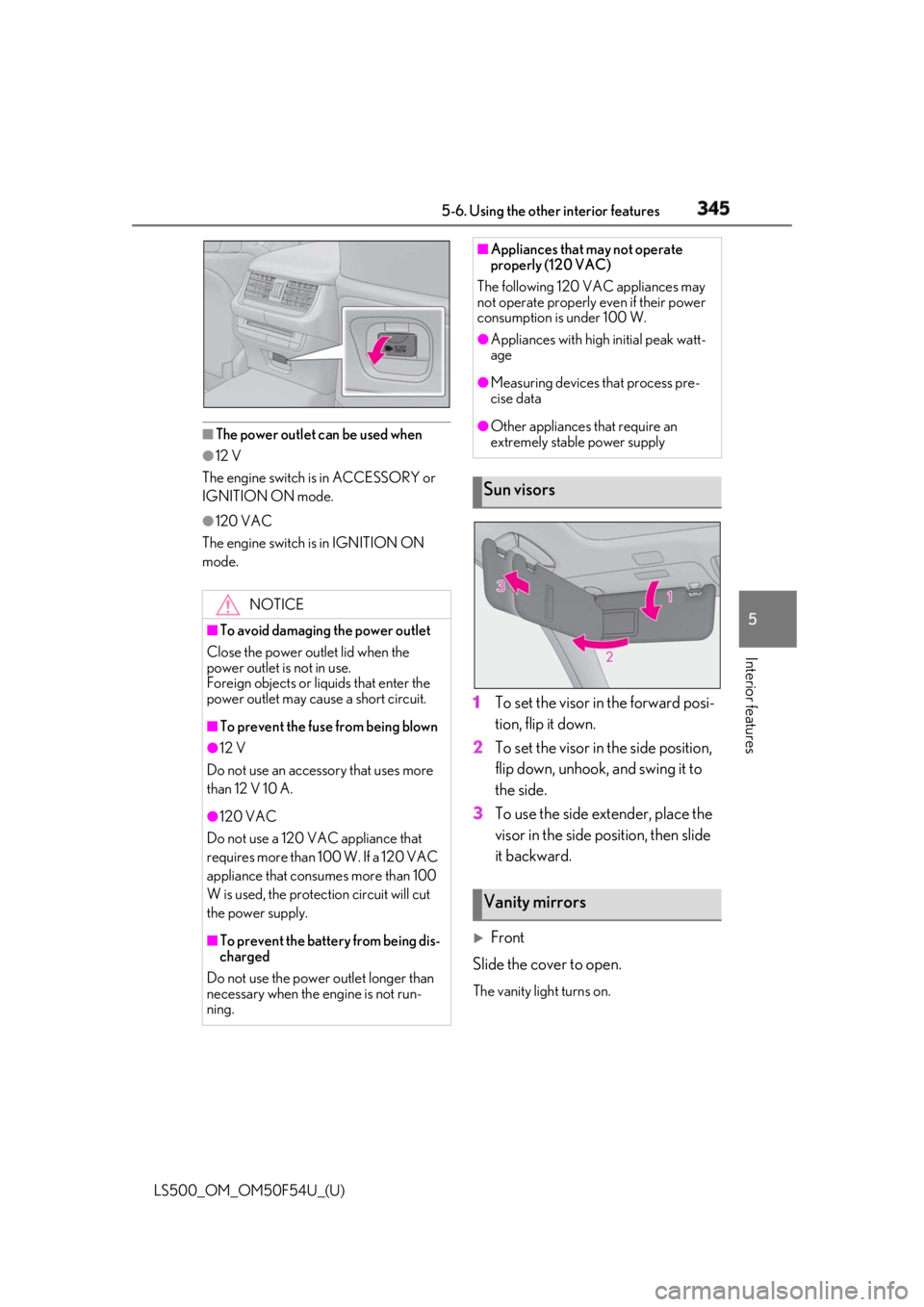
The power outlet can be used when●
12 V
The engine switch is in ACCESSORY or
IGNITION ON mode. ●
120 VAC
The engine switch is in IGNITION ON
mode.
1 To set the visor in the forward posi-
tion, flip it down.
2 To set the visor in the side position,
flip down, unhook, and swing it to
the side.
3 To use the side extender, place the
visor in the side position, then slide
it backward.
Front
Slide the cover to open. The vanity light turns on.NOTICE■
To avoid damaging the power outlet
Close the power outlet lid when the
power outlet is not in use.
Foreign objects or liquids that enter the
power outlet may cause a short circuit. ■
To prevent the fuse from being blown●
12 V
Do not use an accessory that uses more
than 12 V 10 A.
●
120 VAC
Do not use a 120 VAC appliance that
requires more than 100 W. If a 120 VAC
appliance that consumes more than 100
W is used, the protection circuit will cut
the power supply.
■
To prevent the battery from being dis-
charged
Do not use the power outlet longer than
necessary when the engine is not run-
ning. ■
Appliances that may not operate
properly (120 VAC)
The following 120 VAC appliances may
not operate properly even if their power
consumption is under 100 W. ●
Appliances with high initial peak watt-
age ●
Measuring devices that process pre-
cise data ●
Other appliances that require an
extremely stable power supply
Sun visors
Vanity mirrors
Page 347 of 514

3475-6. Using the other interior features
LS500_OM_OM50F54U_(U) 5
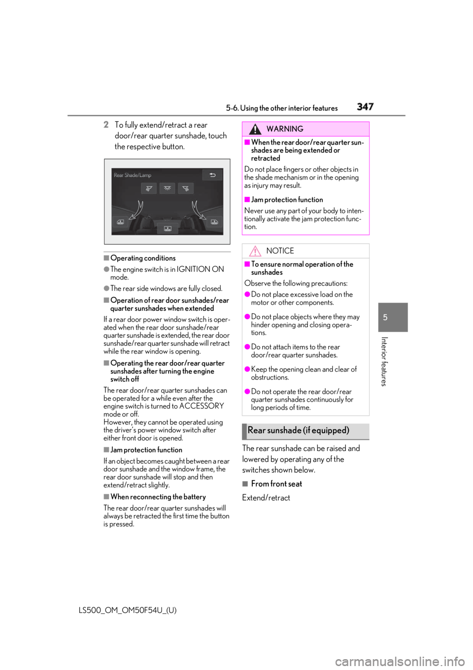
Interior features 2 To fully extend/retract a rear
door/rear quarter sunshade, touch
the respective button.
■
Operating conditions●
The engine switch is in IGNITION ON
mode.●
The rear side windows are fully closed.■
Operation of rear door sunshades/rear
quarter sunshades when extended
If a rear door power window switch is oper-
ated when the rear door sunshade/rear
quarter sunshade is extended, the rear door
sunshade/rear quarter sunshade will retract
while the rear window is opening. ■
Operating the rear door/rear quarter
sunshades after turning the engine
switch off
The rear door/rear quarter sunshades can
be operated for a while even after the
engine switch is turned to ACCESSORY
mode or off.
However, they cannot be operated using
the driver’s power window switch after
either front door is opened.
■
Jam protection function
If an object becomes caught between a rear
door sunshade and the window frame, the
rear door sunshade will stop and then
extend/retract slightly.
■
When reconnecting the battery
The rear door/rear quarter sunshades will
always be retracted the first time the button
is pressed. The rear sunshade can be raised and
lowered by operating any of the
switches shown below. ■
From front seat
Extend/retract WARNING■
When the rear door/rear quarter sun-
shades are being extended or
retracted
Do not place fingers or other objects in
the shade mechanism or in the opening
as injury may result. ■
Jam protection function
Never use any part of your body to inten-
tionally activate the jam protection func-
tion.
NOTICE■
To ensure normal operation of the
sunshades
Observe the following precautions: ●
Do not place excessive load on the
motor or other components. ●
Do not place objects where they may
hinder opening and closing opera-
tions. ●
Do not attach items to the rear
door/rear quarter sunshades. ●
Keep the opening clean and clear of
obstructions.
●
Do not operate the rear door/rear
quarter sunshades continuously for
long periods of time.
Rear sunshade (if equipped)
Page 348 of 514

348 5-6. Using the other interior features
LS500_OM_OM50F54U_(U) ■
From rear seat
Vehicles without power rear seat
Extend/retract
Vehicles with power rear seat
1 Display the home screen and then
touch “Rear Shade/Lamp”.
( → P.308)
2 To fully extend/retract a rear door
sunshade, touch the respective but-
ton.
■
The rear sunshade can be used when
The engine switch is in IGNITION ON
mode. ■
Operating the rear sunshade after turn-
ing the engine switch off
The rear sunshade ca n be operated for a
while even after the engine switch is
switched to ACCESSORY mode or turned
off. ■
Reverse operation feature
To ensure adequate rear visibility, the rear
sunshade automatically lowers when the
shift position is shifted to R.
However, the rear suns hade is raised again
if any of the following occurs: ●
The switch is pressed again.●
The shift position is shifted to P. ●
The shift position is sh ifted out of P and R,
and the vehicle reaches a speed of 9 mph
(15 km/h).
If the engine is turned off when the rear sun-
shade has been lowered due to the reverse
operation feature, it will not be raised even
when the engine is turned on again and the
vehicle reaches a speed of 9 mph (15
km/h). To raise the sunshade again, press
the switch.
WARNING■
When the rear sunshade is being
raised or lowered
Do not place fingers or other objects in
the shade mechanism or in the opening
as injury may result.
NOTICE
■
To ensure normal operation of the
sunshade
Observe the following precautions:
●
Do not place excessive load on the
motor or other components.
●
Do not place objects where they may
hinder opening and closing opera-
tions.
●
Do not attach items to the rear sun-
shade.
Page 357 of 514

3575-6. Using the other interior features
LS500_OM_OM50F54U_(U) 5
Interior features *
: U.S. Patent No. 7,508,298 B2
Stolen Vehicle Location Helps drivers in the event of vehicle theft.
( →
P.358 )
Emergency Assistance Button
(“SOS”) Connects drivers to response-center sup-
port. ( →
P.358 )
Enhanced Roadside Assistance Provides drivers various on-road assis-
tance. ( →
P.358 )
After you have signed the Telematics
Subscription Service Agreement and
are enrolled, you can begin receiving
services.
A variety of subscription terms is avail-
able for purchase. Contact your Lexus
dealer, call 1-800-25-LEXUS
(1-800-255-3987) in the Unites
States (1-877-539-8777 in Puerto
Rico, 1-800-26-LEXUS in Canada) or
push the “SOS” button in your vehicle
for further subscription details. ■
Safety Connect Serv ices Information●
Phone calls using the vehicles Blue-
tooth ®
technology will not be possible
during Safety Connect.
●
Safety Connect is available beginning Fall
2009 on select Lexus models (in the
contiguous United States only). Contact
with the Safety Connect response center
is dependent upon the telematics device
being in operative co ndition, cellular con-
nection availability, and GPS satellite sig-
nal reception, which ca n limit the ability to
reach the response center or receive
emergency service support. Enrollment
and Telematics Subscription Service Agreement required. A variety of sub-
scription terms is available; charges vary
by subscription term selected and loca-
tion. ●
Automatic Collision Notification, Emer-
gency Assistance and Stolen Vehicle
Location will function in the United
States, including Hawaii and Alaska,
Puerto Rico and in Canada, and
Enhanced Roadside Assistance will func-
tion in the United States, Puerto Rico and
in Canada. ●
Automatic Collision Notification, Emer-
gency Assistance, Stolen Vehicle Loca-
tion and Enhanced Roadside Assistance
will not function in the United States Vir-
gin Islands.
No Safety Connect services will function
outside of the United States in countries
other than Canada.
For vehicles first sold in the USVI, no
Safety Connect services will function in
and outside the United States Virgin
Islands. ●
Safety Connect services are not subject
to section 255 of the Telecommunica-
tions Act and the device is not TTY com-
patible. ■
Languages
The Safety Connect re sponse center will
offer support in mult iple languages. The
Safety Connect system will offer voice
prompts in English, Spanish, and French.
Please indicate your language of choice
when enrolling. ■
When contacting the response center
You may be unable to contact the response
center if the network is busy.
When the engine switch is turned to
IGNITION ON mode, the red indica-
tor light comes on for 2 seconds then
turns off. Afterward, the green indica-
tor light comes on, indicating that the
service is active.Subscription
Safety Connect LED light Indi-
cators
Page 374 of 514

374 6-3. Do-it-yourself maintenance
LS500_OM_OM50F54U_(U) Tire inflation pres-
sure ( → P.399) • Tire pressure gauge
•Compressed air
source
Washer fluid
( → P.383) • Water or washer
fluid containing anti-
freeze (for winter
use)
• Funnel (used only for
adding water or
washer fluid)
WARNING
The engine compartment contains many
mechanisms and fluids that may move
suddenly, become hot, or become elec-
trically energized. To avoid death or seri-
ous injury, observe the following
precautions. ■
When working on the engine com-
partment●
Keep hands, clothi ng and tools away
from the moving fan and engine drive
belt.●
Be careful not to touch the engine,
radiator, exhaust manifold, etc. right
after driving as they may be hot. Oil
and other fluids may also be hot.
●
Do not leave anything that may burn
easily, such as paper and rags, in the
engine compartment.
●
Do not smoke, cause sparks or expose
an open flame to fuel. Fuel fumes are
flammable.
■
When working near the electric cool-
ing fan or radiator grille
Be sure the engine switch is off.
With the engine switch in IGNITION
ON mode, the electric cooling fan may
automatically start to run if the air condi-
tioning is on and/or the coolant tempera-
ture is high. ( → P.382)Items Parts and tools ■
Safety glasses
Wear safety glasses to prevent flying or
falling material, fluid spray, etc. from get-
ting in your eyes.
NOTICE■
If you remove the air cleaner filter
Driving with the air cleaner filter
removed may cause excessive engine
wear due to dirt in the air.
Page 389 of 514

3896-3. Do-it-yourself maintenance
LS500_OM_OM50F54U_(U) 6
Maintenance and care before serious problems arise.
The tire pressure detected by the
tire pressure warning system can be
displayed on the multi-information
display. ( → P.76)
If the tire pressure drops below a
predetermined level, the driver is
warned by a screen display and a
warning light. ( → P.422)
■
Routine tire inflation pressure checks
The tire pressure warning system does not
replace routine tire inflation pressure
checks. Make sure to check tire inflation
pressure as part of your routine of daily
vehicle checks.
■
Tire inflation pressure
●
It may take a few minutes to display the
tire inflation pressure after the engine
switch is turned to IGNITION ON mode.
It may also take a few minutes to display
the tire inflation pres sure after inflation
pressure has been adjusted.
●
Tire inflation pressu re changes with tem-
perature. The displayed values may also be different from the values measured
using a tire pressure gauge. ■
Situations in which the tire pressure
warning system may not operate prop-
erly ●
In the following cases, the tire pressure
warning system may not operate prop-
erly.
• If non-genuine Lexus wheels are used.
• If a tire has been replaced with a tire that
is not an OE (Original Equipment) tire.
• If a tire has been replaced with a tire that
is not of the specified size.
• If tire chains, etc. are installed.
• An auxiliary-supported run-flat tire is
equipped.
• If a window tint that affects the radio wave
signals is installed.
• If there is a lot of snow or ice on the vehi-
cle, particularly around the wheels or
wheel housings.
• If the tire inflation pressure is much higher
than the specified level.
• If wheels not equipped with tire pressure
warning valves and transmitter are used.
• If the ID code on the tire pressure warn-
ing valves and transmitters is not regis-
tered in the tire pressure warning
computer. ●
Performance may be af fected in the fol-
lowing situations.
• When driving near a TV tower, electric
power plant, gas stat ion, radio station,
large display, airport or other facility that
generates strong radi o waves or electri-
cal noise
• When carrying a portable radio, cellular
phone, cordless phone or other wireless
communication device
If tire position information is not correctly
displayed due to the radio wave conditions,
the display may be corrected by changing
the location of the vehicle as the radio wave
conditions may change.
●
When the vehicle is stopped, the time
taken for the warning to start or turn off
may be longer.
●
When the inflation pressure of a tire
drops rapidly, for example when a tire has
burst, the warning may not operate.
Page 393 of 514

3936-3. Do-it-yourself maintenance
LS500_OM_OM50F54U_(U) 6
Maintenance and care 5 Press or to select “Vehicle
Settings” and then press .
6 Press or to select “TPWS”
and then press .
7 Press or to select “Set
Pressure”. Then press and hold
until the tire pressure warning light
blinks 3 times.Then a message will be displayed on the
multi-information display.
“--” will be displayed on the multiinforma-
tion display for the inflation pressure of
each tire while initia lization is being per-
formed.
8 Drive straight (with occasional left
and right turns) at approximately
25 mph (40 km/h) or more for
approximately 10 to 30 minutes.Initialization is complete when the position
of each tire is determined and the inflation
pressure of each tire is displayed on the
multi-information display.
Initialization may take longer than approxi-
mately 1 hour in certain situations, such as
when the vehicle is stopped for a long time
at traffic lights, etc. ( → P.393)
■
Initialization procedure
●
Make sure to perform the initialization
procedure after adjusting the tire inflation
pressure.
Also, make sure the tires are cold before performing the initia lization procedure or
adjusting the tire inflation pressure. ●
If the engine switch is turned off during
initialization, it is no t necessary to restart
the initialization procedure from the
beginning as it will begin automatically
when the engine switch is turned back to
IGNITION ON mode. ●
If initialization has accidentally been
started when it is not necessary, adjust
the tire inflation pressure to the specified
level when the tires are cold and then
perform the initiali zation procedure
again. ●
While the position of each tire is being
determined and the inflation pressures
are not being displayed on the
multi-information display, if the inflation
pressure of a tire drops, the tire pressure
warning light will come on. ■
If the tire pressure warning system is not
initialized properly ●
In the following situations, initialization
may take longer than usual to be com-
pleted or may not be possible. (Usually,
the vehicle will need to be driven for
approximately 10 to 30 minutes to com-
plete initialization.) If initialization is not
complete after drivin g approximately 30
minutes, continue driving for a while.
• If the vehicle is driven on an unpaved
road, it may take longer to complete ini-
tialization.
• If the vehicle is backed up while perform-
ing initialization, data collected during ini-
tialization will be cleared and it will take
longer than normal to complete.
• If the vehicle is driven in heavy traffic or
another situation where other vehicles
are driven close by, it may take time for
the system to recognize the tire pressure
warning valve and transmitters of your
vehicle over those of other vehicles.
If initialization is not complete after driving
for approximately 1 hour, park the vehicle in
a safe place for approximately 20 minutes
and then drive the vehicle again.
●
In the following situations, initialization
will not be started or was not completed
properly and the system will not operate
properly. Perform the initialization proce-