Page 219 of 605
4133
Features of your vehicle
If you want to defrost and defog the
front windshield, refer to “Windshield
defrosting and defogging” in this sec-
tion.
Rear window defroster
The defroster heats the window to
remove frost, fog and thin ice from
the rear window, while the engine is
running.To activate the rear window
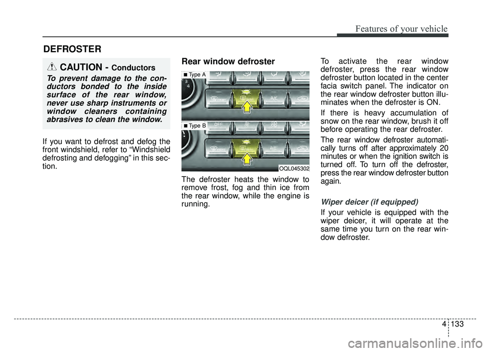
defroster, press the rear window
defroster button located in the center
facia switch panel. The indicator on
the rear window defroster button illu-
minates when the defroster is ON.
If there is heavy accumulation of
snow on the rear window, brush it off
before operating the rear defroster.
The rear window defroster automati-
cally turns off after approximately 20
minutes or when the ignition switch is
turned off. To turn off the defroster,
press the rear window defroster button
again.
Wiper deicer (if equipped)
If your vehicle is equipped with the
wiper deicer, it will operate at the
same time you turn on the rear win-
dow defroster.
DEFROSTER
CAUTION - Conductors
To prevent damage to the con-
ductors bonded to the insidesurface of the rear window,never use sharp instruments orwindow cleaners containingabrasives to clean the window.
OQL045302
■Type A
■ Type B
Page 222 of 605
Features of your vehicle
136
4
Mode selection
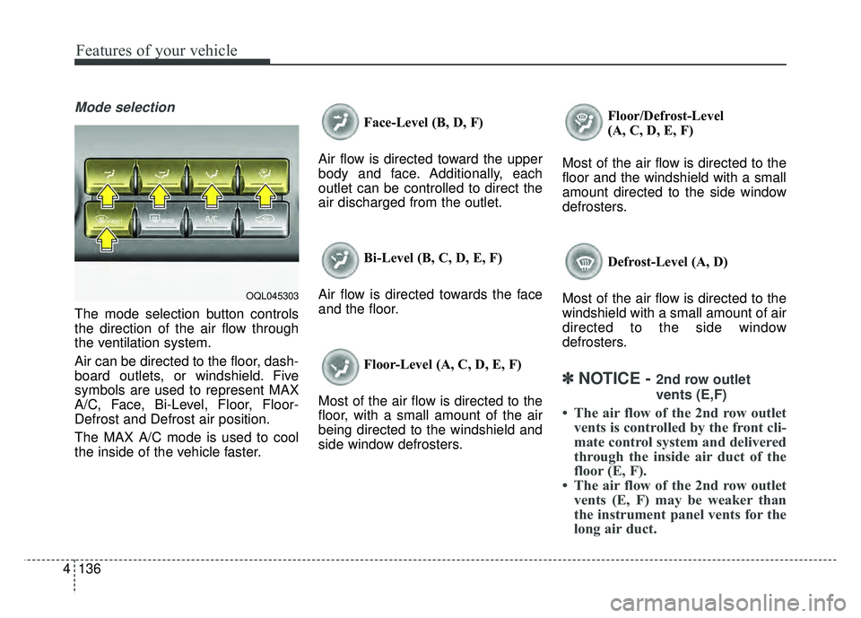
The mode selection button controls
the direction of the air flow through
the ventilation system.
Air can be directed to the floor, dash-
board outlets, or windshield. Five
symbols are used to represent MAX
A/C, Face, Bi-Level, Floor, Floor-
Defrost and Defrost air position.
The MAX A/C mode is used to cool
the inside of the vehicle faster. Face-Level (B, D, F)
Air flow is directed toward the upper
body and face. Additionally, each
outlet can be controlled to direct the
air discharged from the outlet.
Bi-Level (B, C, D, E, F)
Air flow is directed towards the face
and the floor.
Floor-Level (A, C, D, E, F)
Most of the air flow is directed to the
floor, with a small amount of the air
being directed to the windshield and
side window defrosters. Floor/Defrost-Level
(A, C, D, E, F)
Most of the air flow is directed to the
floor and the windshield with a small
amount directed to the side window
defrosters.
Defrost-Level (A, D)
Most of the air flow is directed to the
windshield with a small amount of air
directed to the side window
defrosters.
✽ ✽ NOTICE - 2nd row outlet
vents (E,F)
• The air flow of the 2nd row outlet
vents is controlled by the front cli-
mate control system and delivered
through the inside air duct of the
floor (E, F).
• The air flow of the 2nd row outlet vents (E, F) may be weaker than
the instrument panel vents for the
long air duct.
OQL045303
Page 223 of 605
4137
Features of your vehicle
MAX A/C selection
The MAX A/C mode is used to cool
the inside of the vehicle faster.
Air flow is directed toward the upper
body and face.
In this mode, the air conditioning and
the recirculated air position will be
selected automatically.Instrument panel vents
The outlet vents can be opened or
closed separately using the thumb-
wheel (if equipped).
Also, you can adjust the direction of
air delivery from these vents using
the vent control lever as shown.
Temperature control
The temperature control knob allows
you to control the temperature of the
air flowing from the ventilation system.
To change the air temperature in the
passenger compartment, turn the
knob to the right position for warm and
hot air or left position for cooler air.
OQL045305OQL045307
OQL045306
Page 232 of 605
Features of your vehicle
146
4
✽
✽
NOTICE
Never place anything over the sensor
located on the instrument panel to
ensure better control of the heating
and cooling system.
Manual heating and air condi-
tioning
The heating and cooling system can
be controlled manually by pressing
buttons or turning knob(s) other than
the AUTO button. In this case, the
system works sequentially according
to the order of buttons or knob(s)
selected.
1. Start the engine.
2. Set the mode to the desired posi-
tion.
For improving the effectiveness of
heating and cooling;- Heating:
- Cooling:
3. Set the temperature control to the desired position.
4. Set the air intake control to the outside (fresh) air position.
5. Set the fan speed control to the desired speed.
6. If air conditioning is desired, turn the air conditioning system on.
Press the AUTO button in order to
convert to full automatic control of
the system.
Mode selection
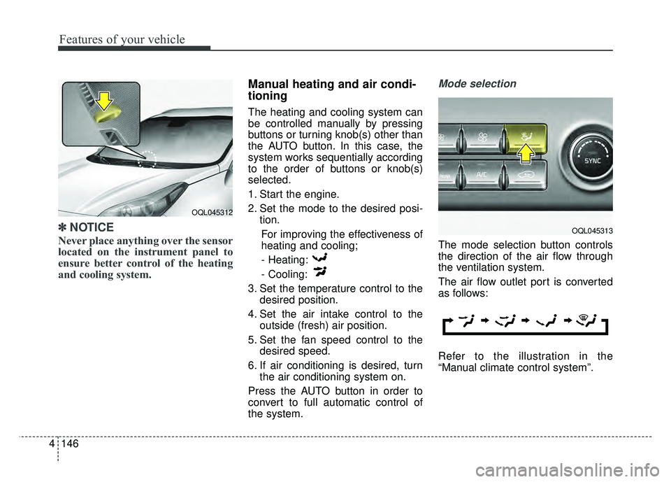
The mode selection button controls
the direction of the air flow through
the ventilation system.
The air flow outlet port is converted
as follows:
Refer to the illustration in the
“Manual climate control system”.
OQL045312
OQL045313
Page 233 of 605
4147
Features of your vehicle
Face-Level
Air flow is directed toward the upper
body and face. Additionally, each
outlet can be controlled to direct the
air discharged from the outlet.
Bi-Level
Air flow is directed towards the face
and the floor.
Floor-Level
Most of the air flow is directed to the
floor, with a small amount of the air
being directed to the windshield and
side window defrosters.
Floor/Defrost-Level
Most of the air flow is directed to the
floor and the windshield with a small
amount directed to the side window
defrosters. Defrost-Level
Most of the air flow is directed to the
windshield with a small amount of air
directed to the side window defrosters.
Instrument panel vents
The outlet vents can be opened or
closed separately using the thumb-
wheel (if equipped).
Also, you can adjust the direction of
air delivery from these vents using
the vent control lever as shown.
OQL045343L
■Type A
■ Type B
OQL045306
Page 424 of 605
697
Driving your vehicle
Turn signals when towing a trailer
When you tow a trailer, your vehicle
has to have a different turn signal
flasher and extra wiring. The green
arrows on your instrument panel will
flash whenever you signal a turn or
lane change. Properly connected,
the trailer lights will also flash to alert
other drivers you’re about to turn,
change lanes, or stop.
When towing a trailer, the green
arrows on your instrument panel will
flash for turns even if the bulbs on
the trailer are burned out. Thus, you
may think drivers behind you are
seeing your signals when, in fact,
they are not. It’s important to check
occasionally to be sure the trailer
bulbs are still working. You must also
check the lights every time you dis-
connect and then reconnect the
wires.
Do not connect a trailer lighting sys-
tem directly to your vehicle’s lighting
system. Use only an approved trailer
wiring harness.
An authorized Kia dealer can assist
you in installing the wiring harness.
Driving on grades
Reduce speed and shift to a lower
gear before you start down a long or
steep downgrade. If you don’t shift
down, you might have to use your
brakes so much that they would get
hot and no longer operate efficiently.
On a long uphill grade, shift down
and reduce your speed to around 45
mph (70 km/h) to reduce the possi-
bility of engine and transaxle over-
heating.
If your trailer weighs more than the
maximum trailer weight without trail-
er brakes and you have an automat-
ic transaxle, you should drive in D
(Drive) when towing a trailer.
Operating your vehicle in D (Drive)
when towing a trailer will minimize
heat build up and extend the life of
your transaxle.CAUTION
Always use an approved trailerwiring harness. Failure to usean approved trailer wiring har-ness could result in damage tothe vehicle electrical system.
Page 533 of 605
863
Maintenance
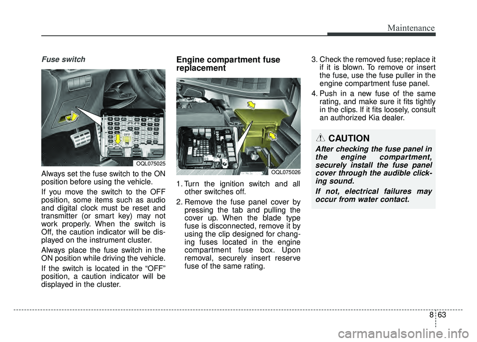
Fuse switch
Always set the fuse switch to the ON
position before using the vehicle.
If you move the switch to the OFF
position, some items such as audio
and digital clock must be reset and
transmitter (or smart key) may not
work properly. When the switch is
Off, the caution indicator will be dis-
played on the instrument cluster.
Always place the fuse switch in the
ON position while driving the vehicle.
If the switch is located in the “OFF”
position, a caution indicator will be
displayed in the cluster.
Engine compartment fuse
replacement
1. Turn the ignition switch and allother switches off.
2. Remove the fuse panel cover by pressing the tab and pulling the
cover up. When the blade type
fuse is disconnected, remove it by
using the clip designed for chang-
ing fuses located in the engine
compartment fuse box. Upon
removal, securely insert reserve
fuse of the same rating. 3. Check the removed fuse; replace it
if it is blown. To remove or insert
the fuse, use the fuse puller in the
engine compartment fuse panel.
4. Push in a new fuse of the same rating, and make sure it fits tightly
in the clips. If it fits loosely, consult
an authorized Kia dealer.
OQL075025
CAUTION
After checking the fuse panel inthe engine compartment,securely install the fuse panelcover through the audible click-ing sound.
If not, electrical failures mayoccur from water contact.
OQL075026
Page 537 of 605
867
Maintenance
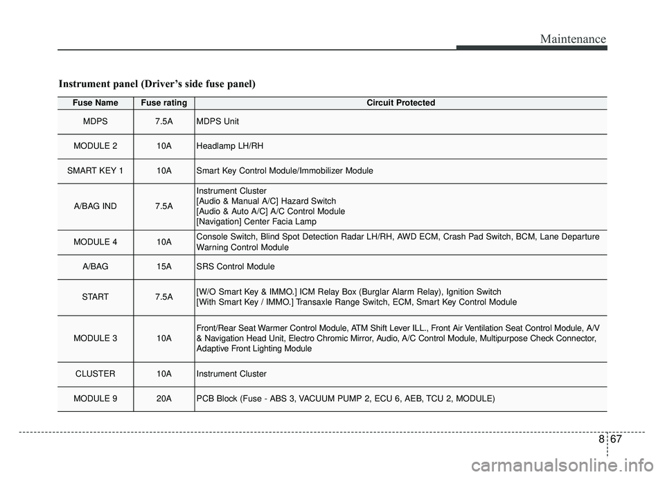
Fuse NameFuse ratingCircuit Protected
MDPS7.5AMDPS Unit
MODULE 210AHeadlamp LH/RH
SMART KEY 110ASmart Key Control Module/Immobilizer Module
A/BAG IND7.5A
Instrument Cluster
[Audio & Manual A/C] Hazard Switch
[Audio & Auto A/C] A/C Control Module
[Navigation] Center Facia Lamp
MODULE 410AConsole Switch, Blind Spot Detection Radar LH/RH, AWD ECM, Crash Pad Switch, BCM, Lane Departure
Warning Control Module
A/BAG15ASRS Control Module
START7.5A[W/O Smart Key & IMMO.] ICM Relay Box (Burglar Alarm Relay), Ignition Switch
[With Smart Key / IMMO.] Transaxle Range Switch, ECM, Smart Key Control Module
MODULE 310AFront/Rear Seat Warmer Control Module, ATM Shift Lever ILL., Front Air Ventilation Seat Control Module, A/V
& Navigation Head Unit, Electro Chromic Mirror, Audio, A/C Control Module, Multipurpose Check Connector,
Adaptive Front Lighting Module
CLUSTER10AInstrument Cluster
MODULE 920APCB Block (Fuse - ABS 3, VACUUM PUMP 2, ECU 6, AEB, TCU 2, MODULE)
Instrument panel (Driver’s side fuse panel)