2018 KIA SOUL check engine
[x] Cancel search: check enginePage 551 of 620

Maintenance
76
8
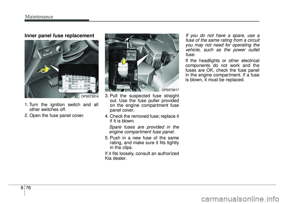
Inner panel fuse replacement
1. Turn the ignition switch and all
other switches off.
2. Open the fuse panel cover. 3. Pull the suspected fuse straight
out. Use the fuse puller provided
on the engine compartment fuse
panel cover.
4. Check the removed fuse; replace it if it is blown.
Spare fuses are provided in theengine compartment fuse panel.
5. Push in a new fuse of the same rating, and make sure it fits tightly
in the clips.
If it fits loosely, consult an authorized
Kia dealer.
If you do not have a spare, use a fuse of the same rating from a circuityou may not need for operating thevehicle, such as the power outletfuse.
If the headlights or other electrical
components do not work and the
fuses are OK, check the fuse panel
in the engine compartment. If a fuse
is blown, it must be replaced.
OPS073017
OPS073014
Page 553 of 620

Maintenance
78
8
3. Check the removed fuse; replace it
if it is blown. To remove or insert
the fuse, use the fuse puller in the
engine compartment fuse panel.
4. Push in a new fuse of the same rating, and make sure it fits tightly
in the clips. If it fits loosely, consult
an authorized Kia dealer.Multi fuse
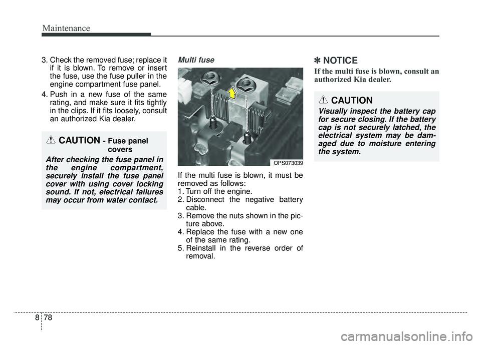
If the multi fuse is blown, it must be
removed as follows:
1. Turn off the engine.
2. Disconnect the negative batterycable.
3. Remove the nuts shown in the pic- ture above.
4. Replace the fuse with a new one of the same rating.
5. Reinstall in the reverse order of removal.
✽ ✽NOTICE
If the multi fuse is blown, consult an
authorized Kia dealer.
OPS073039
CAUTION- Fuse panel
covers
After checking the fuse panel inthe engine compartment,securely install the fuse panelcover with using cover lockingsound. If not, electrical failuresmay occur from water contact.
CAUTION
Visually inspect the battery capfor secure closing. If the batterycap is not securely latched, theelectrical system may be dam-aged due to moisture enteringthe system.
Page 563 of 620

Maintenance
88
8
LIGHT BULBS
Bulb replacement precaution
Please keep extra bulbs on hand
with appropriate wattage ratings in
case of emergencies.
Refer to “Bulb Wattage” in chapter 9.
When changing lamps, first turn off
the engine at a safe place, firmly
apply the parking brake and detach
the battery’s negative (-) terminal.
Use only bulbs of the specified
wattage.✽ ✽ NOTICE
• If the light bulb or lamp connector
is removed while the lamp is still
on, the fuse box's electronic sys-
tem may log it as a malfunction.
Therefore, a lamp malfunction
incident may be recorded as a
Diagnostic Trouble Code (DTC) in
the fuse box.
• It is normal for an operating lamp to flicker momentarily. This is due
to a stabilization function of the
vehicle’s electronic control device.
If the lamp lights up normally
after momentarily blinking, then
it is functioning as normal.
However, if the lamp continues to
flicker several times or turns off
completely, there may be an error
in the vehicle’s electronic control
device. Please have the vehicle
checked by an authorized Kia
dealer immediately.
WARNING- Working on
the lights
Prior to working on the light,
firmly apply the parking brake,
ensure that the ignition switch
is turned to the LOCK position
and turn off the lights to avoid
sudden movement of the vehi-
cle and burning your fingers or
receiving an electric shock.
CAUTION -Light replace-
ment
Be sure to replace the burned- out bulb with one of the samewattage rating. Otherwise, itmay cause damage to the fuseor electric wiring system.
CAUTION -Headlamp
Lens
To prevent damage, do notclean the headlamp lens withchemical solvents or strongdetergents.
Page 590 of 620

8115
Maintenance
Canister
Fuel vapors generated inside the fuel
tank are absorbed and stored in the
onboard canister. When the engine is
running, the fuel vapors absorbed in
the canister are drawn into the surge
tank through the purge control sole-
noid valve.
Purge Control Solenoid Valve(PCSV)
The purge control solenoid valve is
controlled by the Engine Control
Module (ECM); when the engine
coolant temperature is low during
idling, the PCSV closes so that evap-
orated fuel is not taken into the
engine. After the engine warms up
during ordinary driving, the PCSV
opens to introduce evaporated fuel to
the engine.
3. Exhaust emission control
system
The Exhaust Emission Control
System is a highly effective system
which controls exhaust emissions
while maintaining good vehicle per-
formance.
Vehicle modifications
This vehicle should not be modified.
Modification of your vehicle could
affect its performance, safety or
durability and may even violate gov-
ernmental safety and emissions reg-
ulations.
In addition, damage or performance
problems resulting from any modifi-
cation may not be covered under
warranty.
If you use unauthorized electronic
devices, it may cause the vehicle to
operate abnormally, wire damage,
battery discharge and fire. For your
safety, do not use unauthorized
electronic devices.
Engine exhaust gas precautions
(carbon monoxide)
Carbon monoxide can be present with other exhaust fumes.
Therefore, if you smell exhaust
fumes of any kind inside your vehi-
cle, have it inspected and repaired
immediately. If you ever suspect
exhaust fumes are coming into
your vehicle, drive it only with all
the windows fully open. Have your
vehicle checked and repaired
immediately.
WARNING - Exhaust
Engine exhaust gases contain
carbon monoxide (CO). Though
colorless and odorless, it is
dangerous and could be lethal if
inhaled. Follow the instructions
on this page to avoid CO poi-
soning.
Page 612 of 620

Index
4I
To temporarily accelerate with the cruise control on . . . . . . . . . . . . . . . . . . . . . . . . . . . . . . . . . . . . \
. . 6-64
To turn cruise control off, do one of the following . 6-66
Declaration of Conformity . . . . . . . . . . . . . . . . . . . . . . 5-84 FCC . . . . . . . . . . . . . . . . . . . . . . . . . . . . . . . . . . . . \
. 5-84
Defroster . . . . . . . . . . . . . . . . . . . . . . . . . . . . . . . . . . . 4-\
101 Rear window defroster . . . . . . . . . . . . . . . . . . . . . . 4-101
Dimensions . . . . . . . . . . . . . . . . . . . . . . . . . . . . . . . . . . . 9-\
2
Door locks. . . . . . . . . . . . . . . . . . . . . . . . . . . . . . . . . . . 4-\
17 Auto door lock/unlock feature . . . . . . . . . . . . . . . . . 4-20
Child-protector rear door lock . . . . . . . . . . . . . . . . . 4-21
Impact sensing door unlock system . . . . . . . . . . . . . 4-20
Operating door locks from inside the vehicle . . . . . 4-18
Operating door locks from outside the vehicle . . . . 4-17
Speed sensing door lock system . . . . . . . . . . . . . . . 4-20
Drive mode integrated control system . . . . . . . . . . . . . 6-84
Dual Clutch Transmission (DCT). . . . . . . . . . . . . . . . . 6-25 Dual clutch transmission operation . . . . . . . . . . . . . 6-25
Good driving practices . . . . . . . . . . . . . . . . . . . . . . . 6-33
Economical operation . . . . . . . . . . . . . . . . . . . . . . . . . 6-103
Electrical equipment (U.S. Only) . . . . . . . . . . . . . . . . . 9-15 Emergency starting . . . . . . . . . . . . . . . . . . . . . . . . . . . . . 7-5
Jump starting . . . . . . . . . . . . . . . . . . . . . . . . . . . . . . . 7-5
Push-starting . . . . . . . . . . . . . . . . . . . . . . . . . . . . . . . . 7-7
Emission control system . . . . . . . . . . . . . . . . . . . . . . . 8-114 Crankcase emission control system . . . . . . . . . . . . 8-114
Evaporative emission control (including ORVR:Onboard Refueling Vapor Recovery) system. . . . 8-114
Exhaust emission control system . . . . . . . . . . . . . . 8-115
Engine . . . . . . . . . . . . . . . . . . . . . . . . . . . . . . . . . . . . \
. . . 9-3
Engine compartment . . . . . . . . . . . . . . . . . . . . . . . . 2-6, 8-3
Engine coolant . . . . . . . . . . . . . . . . . . . . . . . . . . . . . . . 8-42 Changing the coolant . . . . . . . . . . . . . . . . . . . . . . . . 8-44
Checking the coolant level . . . . . . . . . . . . . . . . . . . . 8-42
Engine number . . . . . . . . . . . . . . . . . . . . . . . . . . . . . . . 9-11
Engine oil . . . . . . . . . . . . . . . . . . . . . . . . . . . . . . . . . . . 8-\
40 Changing the engine oil and filter . . . . . . . . . . . . . . 8-41
Checking the engine oil level . . . . . . . . . . . . . . . . . . 8-40
Engine start/stop button . . . . . . . . . . . . . . . . . . . . . . . . . 6-9 Engine start/stop button position . . . . . . . . . . . . . . . . 6-8
Illuminated engine start/stop button. . . . . . . . . . . . . . 6-9
Starting the engine with a smart key . . . . . . . . . . . . 6-11
Explanation of scheduled maintenance items . . . . . . . 8-34
Exterior features . . . . . . . . . . . . . . . . . . . . . . . . . . . . . 4-147 Mounting bracket for roof carrier . . . . . . . . . . . . . 4-148
Roof rack . . . . . . . . . . . . . . . . . . . . . . . . . . . . . . . . 4-147
Exterior overview . . . . . . . . . . . . . . . . . . . . . . . . . . . . . . 2-2
D
E