Page 348 of 490
What to do in an emergency
30
7
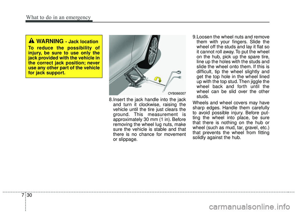
8.Insert the jack handle into the jack
and turn it clockwise, raising the
vehicle until the tire just clears the
ground. This measurement is
approximately 30 mm (1 in). Before
removing the wheel lug nuts, make
sure the vehicle is stable and that
there is no chance for movement
or slippage. 9.Loosen the wheel nuts and remove
them with your fingers. Slide the
wheel off the studs and lay it flat so
it cannot roll away. To put the wheel
on the hub, pick up the spare tire,
line up the holes with the studs and
slide the wheel onto them. If this is
difficult, tip the wheel slightly and
get the top hole in the wheel lined
up with the top stud. Then jiggle the
wheel back and forth until the
wheel can be slid over the other
studs.
Wheels and wheel covers may have
sharp edges. Handle them carefully
to avoid possible injury. Before put-
ting the wheel into place, be sure
that there is nothing on the hub or
wheel (such as mud, tar, gravel, etc.)
that prevents the wheel from fitting
solidly against the hub.
WARNING - Jack location
To reduce the possibility of
injury, be sure to use only the
jack provided with the vehicle in
the correct jack position; never
use any other part of the vehicle
for jack support.
OYB066007
Page 349 of 490
731
What to do in an emergency
10. To install the wheel, hold it on thestuds, put the wheel nuts on the
studs and tighten them finger
tight. Jiggle the tire to be sure it is
completely seated, then tighten
the nuts as much as possible
with your fingers again.
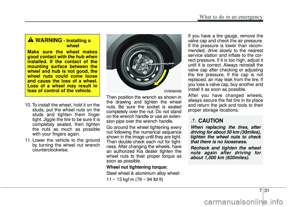
11. Lower the vehicle to the ground by turning the wheel nut wrench
counterclockwise. Then position the wrench as shown in
the drawing and tighten the wheel
nuts. Be sure the socket is seated
completely over the nut. Do not stand
on the wrench handle or use an exten-
sion pipe over the wrench handle.
Go around the wheel tightening every
nut following the numerical sequence
shown in the image until they are tight.
Then double-check each nut for tight-
ness. After changing the wheels, have
an authorized Kia dealer tighten the
wheel nuts to their proper torque as
soon as possible.
Wheel nut tightening torque:
Steel wheel & aluminium alloy wheel:
11 ~ 13 kgf·m (79 ~ 94 lbf·ft) If you have a tire gauge, remove the
valve cap and check the air pressure.
If the pressure is lower than recom-
mended, drive slowly to the nearest
service station and inflate to the cor-
rect pressure. If it is too high, adjust it
until it is correct. Always reinstall the
valve cap after checking or adjusting
the tire pressure. If the cap is not
replaced, air may leak from the tire. If
you lose a valve cap, buy another and
install it as soon as possible.
After you have changed wheels,
always secure the flat tire in its place
and return the jack and tools to their
proper storage locations.
WARNING- Installing a
wheel
Make sure the wheel makes
good contact with the hub when
installed. If the contact of the
mounting surface between the
wheel and hub is not good, the
wheel nuts could come loose
and cause the loss of a wheel.
Loss of a wheel may result in
loss of control of the vehicle.
OYB066008
CAUTION
When replacing the tires, after driving for about 50 km (30miles),tighten the wheel nuts to checkthat there is no looseness.
Recheck and tighten the wheelnuts again after driving forabout 1,000 km (620miles).
Page 355 of 490
737
What to do in an emergency
When towing your vehicle in an
emergency without wheel dollies :
1.Set the ignition switch in the ACCposition.
2.Place the transaxle shift lever in N (Neutral).
3.Release the parking brake.Removable towing hook (front)
(if equipped)
1.Remove the towing hook from the tool case.
2.Remove the hole cover pressing the lower part of the cover on the
front bumper.
3.Install the towing hook by turning it clockwise into the hole until it is
fully secured.
4.Remove the towing hook and install the cover after use.
Emergency towing
CAUTION- Towing gear
position
Always place the transaxle shiftlever in N (Neutral) when towingyour vehicle. Failure to place thetransaxle shift lever in N(Neutral) may cause internaldamage to the transaxle.
OSC067008N
OSC067009N
OSC067010N
OYB066017
Page 386 of 490
829
Maintenance
ENGINE COOLANT
The high-pressure cooling system
has a reservoir filled with year round
antifreeze coolant. The reservoir is
filled at the factory.
Check the antifreeze protection and
coolant level at least once a year: at
the beginning of the winter season,
and before traveling to a colder cli-
mate.Checking the coolant level Turn the engine off and wait until itcools down. Use extreme care
when removing the radiator cap.
Wrap a thick towel around it, and
turn it counterclockwise slowly to
the first stop. Step back while the
pressure is released from the cool-
ing system.
When you are sure all the pressure
has been released, press down on
the cap, using a thick towel, and
continue turning counterclockwise
to remove it.
Even if the engine is not operating, do not remove the radiator cap or
the drain plug while the engine and
radiator are hot. Hot coolant and
steam may still blow out under
pressure, causing serious injury.
WARNING
Removing radiator
cap
Never attempt to remove the
radiator cap while the engine is
operating or hot. Doing so
might lead to cooling system
and engine damage and could
result in serious personal injury
from escaping hot coolant or
steam.
CAUTION - Radiator cap
Never attempt to remove the radiator cap while the engine isoperating or hot. Doing somight lead to cooling systemand engine damage.
Page 420 of 490
863
Maintenance
✽ ✽NOTICE
• Set all switches to ON before driv-
ing.
• If the vehicle is going to be unused for over 1 month, set all switches
to OFF to prevent the batteries
from draining.
Memory fuse
Your vehicle is equipped with the
memory fuse to prevent battery dis-
charge if your vehicle is parked with-
out being operated for prolonged
periods. Use the following proce-
dures before parking the vehicle for
prolonged periods.
1. Turn off the engine.
2. Turn off the headlights and tail
lights.
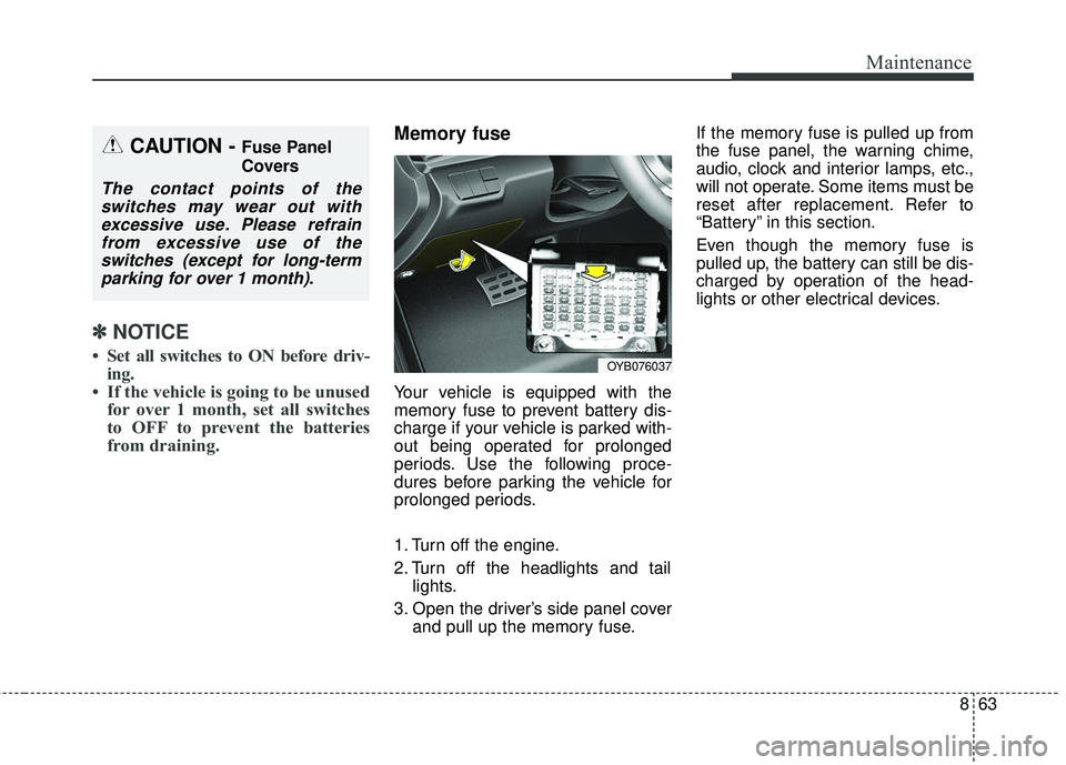
3. Open the driver’s side panel cover and pull up the memory fuse. If the memory fuse is pulled up from
the fuse panel, the warning chime,
audio, clock and interior lamps, etc.,
will not operate. Some items must be
reset after replacement. Refer to
“Battery” in this section.
Even though the memory fuse is
pulled up, the battery can still be dis-
charged by operation of the head-
lights or other electrical devices.
CAUTION - Fuse Panel
Covers
The contact points of the
switches may wear out withexcessive use. Please refrainfrom excessive use of theswitches (except for long-termparking for over 1 month).
OYB076037
Page 425 of 490

Maintenance
68
8
Fuse NameFuse ratingCircuit Protected
TCU15AEngine Room Junction Block(Back-Up Lamp Switch), Auto Transmission Shift Lever, Transaxle Range
Switch, Stop Lamp Switch
P/WINDOW LH25APower Window Main Switch
SPARE125ASpare
FOG LAMP REAR10A-
HEATED STEERING15AClock Spring
TAIL LAMP LH7.5AHead Lamp Left Handle side, License Lamp Left Handle side, Rear Combination Lamp (OUT) Left
Handle side, Rear Combination Lamp (IN) Left Handle side, Glove Box Lamp
MODULE37.5AFront Seat Warmer Control Module, Audio, Electro Chromic Mirror, Air Conditioner Control Module,
Audio/Video & Navigation Head Unit, Clock Spring, Auto Transmission Shift Lever Indicator
ABS7.5AEngine Room Junction Block(Multipurpose Check Connector), ESC (Electronic Stability Control) Module
BRAKE SWITCH10ASmart Key Control Module, Stop Lamp Switch
SPARE415ASpare
FOG LAMP FRONT15AFront Fog Lamp Relay
A/CON17.5AEngine Room Junction Block(Blower Relay), Air Conditioner Control Module
MODULE510AEngine Room Junction Block(Head Lamp Relay, Head Lamp Hi Relay), Rain Sensor, Sunroof Motor,
Front Seat Warmer Control Module, Driver Safety Power Window Module
MODULE710ATPMS (Tire Pressure Monitoring System) Unit
ECU10AECM (Engine Control Module)/PCM (Power train Control Module), Immobilizer Module, Smart Key
Control Module
Page 437 of 490
Maintenance
80
8
Light bulb position (Side)
(1) Side repeater lamp (LED type)
(2) Side repeater lamp (bulb type)
Headlamp (Low/High beam)
bulb replacement
(Headlamp Type A)
1. Open the hood.
2. Remove the headlamp bulb cover
by turning it counterclockwise.
3. Disconnect the headlamp bulb socket-connector.
4. Unsnap the headlamp bulb retain- ing wire by pressing the end and
pushing it upward.
5. Remove the bulb from the head lamp assembly. 6. Install a new headlamp bulb and
snap the headlamp bulb retaining
wire into position by aligning the
wire with the groove on the bulb.
7. Connect the headlamp bulb sock- et-connector.
8. Install the headlamp bulb cover by turning it clockwise.
OYB076047
OYB076048
■Type A
■Type B
OYB076049
Page 438 of 490
881
Maintenance
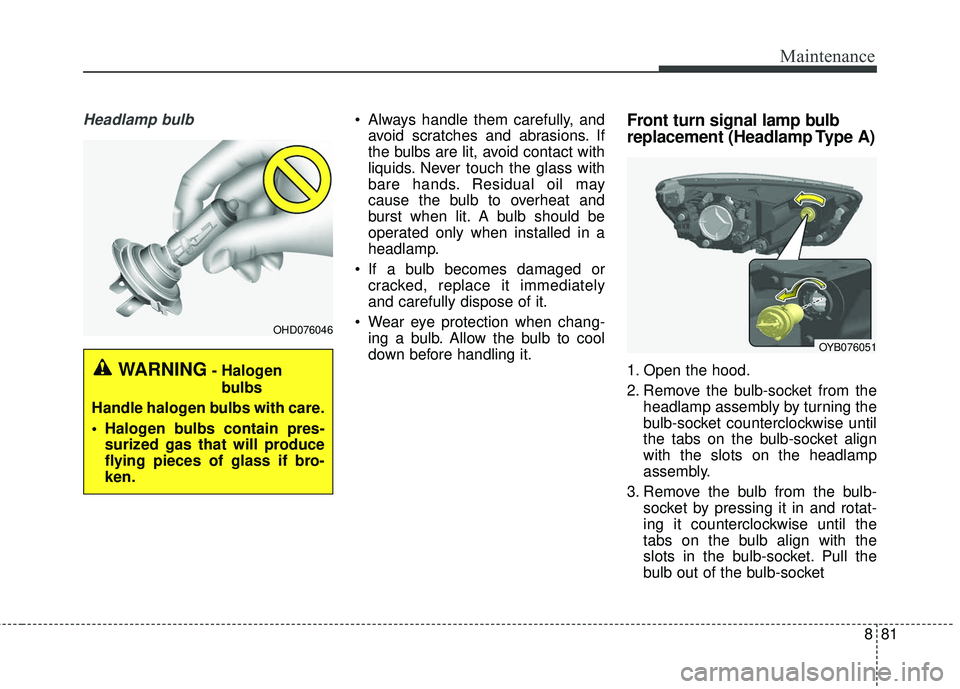
Headlamp bulb Always handle them carefully, andavoid scratches and abrasions. If
the bulbs are lit, avoid contact with
liquids. Never touch the glass with
bare hands. Residual oil may
cause the bulb to overheat and
burst when lit. A bulb should be
operated only when installed in a
headlamp.
If a bulb becomes damaged or cracked, replace it immediately
and carefully dispose of it.
Wear eye protection when chang- ing a bulb. Allow the bulb to cool
down before handling it.Front turn signal lamp bulb
replacement (Headlamp Type A)
1. Open the hood.
2. Remove the bulb-socket from the headlamp assembly by turning the
bulb-socket counterclockwise until
the tabs on the bulb-socket align
with the slots on the headlamp
assembly.
3. Remove the bulb from the bulb- socket by pressing it in and rotat-
ing it counterclockwise until the
tabs on the bulb align with the
slots in the bulb-socket. Pull the
bulb out of the bulb-socketWARNING- Halogen
bulbs
Handle halogen bulbs with care.
Halogen bulbs contain pres- surized gas that will produce
flying pieces of glass if bro-
ken.
OHD076046
OYB076051