Page 276 of 547
Audio system
55
How vehicle radio works
FM reception
AM and FM radio signals are broad-
cast from transmitter towers located
around your city. They are intercept-
ed by the radio antenna on your vehi-
cle. This signal is then processed by
the radio and sent to your vehicle
speakers.
However, in some cases the signal
coming to your vehicle may not be
strong and clear.This can be due to factors, such as
the distance from the radio station,
closeness of other strong radio sta-
tions or the presence of buildings,
bridges or other large obstructions in
the area.
AM reception
AM broadcasts can be received at
greater distances than FM broad-
casts. This is because AM radio
waves are transmitted at low fre-
quencies. These long distance,low
frequency radio waves can follow the
curvature of the earth rather than
travelling straight. In addition, they
curve around obstructions resulting
in better signal coverage.OJF045308L
OJF045309L
Page 277 of 547

Audio system
65
FM radio station
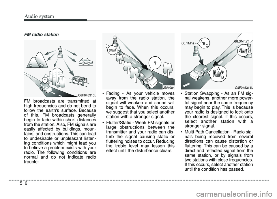
FM broadcasts are transmitted at
high frequencies and do not bend to
follow the earth's surface. Because
of this, FM broadcasts generally
begin to fade within short distances
from the station. Also, FM signals are
easily affected by buildings, moun-
tains, and obstructions. This can lead
to undesirable or unpleasant listen-
ing conditions which might lead you
to believe a problem exists with your
radio. The following conditions are
normal and do not indicate radio
trouble: Fading - As your vehicle moves
away from the radio station, the
signal will weaken and sound will
begin to fade. When this occurs,
we suggest that you select another
station with a stronger signal.
Flutter/Static - Weak FM signals or large obstructions between the
transmitter and your radio can dis-
turb the signal causing static or
fluttering noises to occur. Reducing
the treble level may lessen this
effect until the disturbance clears. Station Swapping - As an FM sig-
nal weakens, another more power-
ful signal near the same frequency
may begin to play. This is because
your radio is designed to lock onto
the clearest signal. If this occurs,
select another station with a
stronger signal.
Multi-Path Cancellation - Radio sig- nals being received from several
directions can cause distortion or
fluttering. This can be caused by a
direct and reflected signal from the
same station, or by signals from
two stations with close frequencies.
If this occurs, select another station
until the condition has passed.
¢¢¢
JBM004
OJF045310L
OJF045311L
Page 278 of 547
Audio system
57
Using a cellular phone or a two-way radio
When a cellular phone is used inside
the vehicle, noise may be produced
from the audio system. This does not
mean that something is wrong with
the audio equipment. In such a case,
try to operate mobile devices as far
from the audio equipment as possible.
When using a communication sys-
tem such as a cellular phone or a
radio set inside the vehicle, a sepa-
rate external antenna must be fitted.
When a cellular phone or a radio set
is used with an internal antenna
alone, it may interfere with the vehi-
cle's electrical system and adversely
affect safe operation of the vehicle.
WARNING- Cell phone use
Do not use a cellular phone
while driving. Stop at a safe
location to use a cellular phone.
Page 279 of 547

Audio system
85
Declaration of Conformity
FCC
This equipment has been tested and found to comply with the limits for a Class B digital device, pursuant to part 15
of the FCC Rules. These limits are designed to provide reasonable protection against harmful interference in a resi-
dential installation.
This equipment generates, uses and can radiate radio frequency energy and, if not installed and used in accordance
with the instructions,may cause harmful interference to radio communications. However, there is no guarantee that
interference will not occur in a particular installation. If this equipment does cause harmful interference to radio or tel-
evision reception, which can be determined by turning the equipment off and on, the user is encouraged to try to cor-
rect the interference by one or more of the following measures : Reorient or relocate the receiving antenna.
Increase the separation between the equipment and receiver.
Connect the equipment into an outlet on a circuit different from that to which the receiver is connected.
Consult the dealer or an experienced radio/TV technician for help.
Caution: Any changes or modifications to this device not explicitly approved by manufacturer could void
your authority to operate this equipment.
Page 280 of 547
Audio system
59
This device complies with part 15 of the FCC Rules. Operation is subject to the following two conditions :
(1) This device may not cause harmful interference, and (2) this device must accept any interference received, includ-
ing interference that may cause undesired operation.
This equipment complies with FCC radiation exposure limits set forth for an uncontrolled environment.
This equipment should be installed and operatedwith minmum 20cm between the and your body. This transmitter must
not be collocated or operating in conjunction with any other antenna or transmitter unless authorized to do so by the
FCC.
Page 456 of 547

Maintenance
44
8
When recharging the battery,
observe the following precautions:
The battery must be removed from
the vehicle and placed in an area
with good ventilation.
Do not allow cigarettes, sparks, or flame near the battery.
Watch the battery during charging, and stop or reduce the charging
rate if the battery cells begin
gassing (boiling) violently or if the
temperature of the electrolyte of
any cell exceeds 120°F (49°C).
Wear eye protection when check- ing the battery during charging.
Disconnect the battery charger in the following order.
1. Turn off the battery charger main switch.
2. Unhook the negative clamp from the negative battery terminal.
3. Unhook the positive clamp from the positive battery terminal. Before performing maintenance or
recharging the battery, turn off all
accessories and stop the engine.
The negative battery cable must be removed first and installed last
when the battery is disconnected.Reset items
Items should be reset after the bat-
tery has been discharged or the bat-
tery has been disconnected.
Auto up/down window (See chapter 4)
Sunroof (See chapter 4)
Trip computer (See chapter 4)
Climate control system (See chapter 4)
Driver position memory system (See chapter 3)
Audio (See chapter 5)
Page 475 of 547

863
Maintenance
Fuse switch
Always set the fuse switch to the ON
position before using the vehicle.
If you move the switch to the OFF
position, some items such as audio
and digital clock must be reset and
transmitter (or smart key) may not
work properly. When the switch is
Off, the caution indicator will be dis-
played on the instrument cluster.
Always place the fuse switch in the
ON position while driving the vehicle.
If the switch is located in the “OFF”
position, a caution indicator will be
displayed in the cluster.
Engine compartment fuse
replacement
1. Turn the engine start/stop buttonto the OFF position and all other
switches off.
2. Remove the fuse panel cover by pressing the tab and pulling the
cover up. When the blade type
fuse is disconnected, remove it by
using the clip designed for chang-
ing fuses located in the engine
compartment fuse box. Upon
removal, securely insert reserve
fuse of the same rating. 3. Check the removed fuse; replace it
if it is blown. To remove or insert
the fuse, use the fuse puller in the
engine compartment fuse panel.
4. Push in a new fuse of the same rating, and make sure it fits tightly
in the clips. If it fits loosely, consult
an authorized Kia dealer.
OJF075024
CAUTION
After checking the fuse panel inthe engine compartment,securely install the fuse panelcover through the audible click-ing sound.
If not, electrical failures mayoccur from water contact.
OJFH075025
Page 480 of 547
Maintenance
68
8
Fuse NameFuse ratingCircuit Protected
MDPS10AMDPS Unit (Column/Rack)
IG125APCB Block (Fuse - OPCU2/ELECTRICAL WATER PUMP/TCU2/ACTIVE HYDRAULIC BOOTER 3/HEV
ECU2/ECU3)
MODULE 910ASmart Key Control Module
WASHER15AMultifunction Switch (Wiper Low & Washer Switch)
MODULE 810ADriver/Passenger Door Module
CLUSTER10AInstrument Cluster
MULTI MEDIA15AAudio, A/V & Navigation Head Unit, Keyboard
HTD STRG15ABCM (Steering Wheel Heated)
MODULE 110AConsole Switch, Active Air Flap Unit, Gateway, Driver/Passenger Door Module
DR LOCK20ADoor Lock Relay, Door Unlock Relay, ICM Relay Box (Dead Lock Relay)
MEMORY 210ASiren Control Module, Ultrasonic Instrusion Protection Sensor
SMART KEY15ASmart Key Control Module