Page 33 of 348
WARNING!
• A loose head restraint thrown forward in
a collision or hard stop could cause se-
rious injury or death to occupants of the
vehicle. Always securely stow removed
WARNING!
head restraints in a location outside the
occupant compartment.
• ALL the head restraints MUST be rein-
stalled in the vehicle to properly protect
the occupants. Follow the re-installation
instructions above prior to operating the
vehicle or occupying a seat.
NOTE:
Do not reposition the head restraint 180 de-
grees to the incorrect position in an attempt
to gain additional clearance to the back of the
head.
Rear Head Restraints — Two Door Models
The rear seat is equipped with non-
adjustable, but foldable head restraints.
To fold the outboard head restraint, pull on
the release strap located on the upper out-
board side of each rear seat.
Front Head Restraint
1 — Release Button
2 — Adjustment Button
Rear Head Restraint Folding Strap
Location
31
Page 34 of 348

To return the head restraint to its upward
position, lift up on the head restraint until it
locks into place.
Refer to “Occupant Restraint Systems” in
“Safety” for information on child seat tether
routing.
WARNING!
• Do not drive the vehicle without the rear
seat head restraints installed while pas-
sengers are occupying the rear seat. In a
collision, people riding in this area with-
out the head restraints installed are
more likely to be seriously injured or
killed.
• A loose head restraint thrown forward in
a collision or hard stop could cause
serious injury or death to occupants of
the vehicle. Always securely stow re-
moved head restraints in a location out-
side the occupant compartment.
• ALL the head restraints MUST be rein-
stalled in the vehicle to properly protect
the occupants. Follow the reinstallation
instructions above prior to operating the
vehicle or occupying a seat.
Rear Head Restraints — Four Door Models
The rear seat is equipped with nonadjustable,
but foldable, outboard head restraints, as
well as an adjustable, removable center head
restraint.To fold the outboard head restraint, pull on
the inner release lever, located on the upper
part of the rear seat.
To return the head restraint to its upward
position, lift up on the head restraint until it
locks into place.
Rear Head Restraints Folded
Rear Head Restraint Lever Location
1 — Seatback Release Lever
2 — Head Restraint Release LeverGETTING TO KNOW YOUR VEHICLE
32
Page 35 of 348

To raise the center head restraint, lift up on
the head restraint. To lower the center head
restraint, push the adjustment button, lo-
cated at the base of the head restraint, and
push down on the head restraint.
To remove the center head restraint, push the
release button, located on the base of the
head restraint, and pull upward on the head
restraint.
To install the head restraint, hold the release
button while pushing downward on the head
restraint. Refer to “Occupant Restraint Sys-
tems” in “Safety” for information on child
seat tether routing.
NOTE:
Lower the center head restraint to avoid con-
tact with the center console when folding the
seat down.
WARNING!
• Do not drive the vehicle without the rear
seat head restraints installed while pas-
sengers are occupying the rear seat. In a
collision, people riding in this area with-
WARNING!
out the head restraints installed are
more likely to be seriously injured or
killed.
• A loose head restraint thrown forward in
a collision or hard stop could cause se-
rious injury or death to occupants of the
vehicle. Always securely stow removed
head restraints in a location outside the
occupant compartment.
• ALL the head restraints MUST be rein-
stalled in the vehicle to properly protect
the occupants. Follow the reinstallation
instructions above prior to operating the
vehicle or occupying a seat.
STEERING WHEEL
Tilt/Telescoping Steering Column
This feature allows you to tilt the steering
column upward or downward. It also allows
you to lengthen or shorten the steering col-
umn. The tilt/telescoping lever is located on
the steering column, below the turn signal
lever.To unlock the steering column, push the
control handle downward (toward the floor).
To tilt the steering column, move the steering
wheel upward or downward as desired. To
lengthen or shorten the steering column, pull
the steering wheel outward or push it inward
as desired. To lock the steering column in
position, push the control handle upward
until fully engaged.
Tilt/Telescoping Steering Column Lever
33
Page 36 of 348

WARNING!
Do not adjust the steering column while
driving. Adjusting the steering column
while driving or driving with the steering
column unlocked, could cause the driver
to lose control of the vehicle. Failure to
follow this warning may result in serious
injury or death.
Heated Steering Wheel — If Equipped
The steering wheel contains a heating ele-
ment that helps warm your hands in cold
weather. The heated steering wheel has only
one temperature setting. Once the heated
steering wheel has been turned on, it will stay
on until the operator turns it off. The heated
steering wheel may not turn on when it is
already warm.
The heated steering wheel control button is
located on the center of the instrument panel
below the touchscreen and within the climate
or controls screen of the touchscreen.• Push the heated steering wheel button
once to turn the heating element on.
• Push the heated steering wheel button
a second time to turn the heating element
off.
NOTE:
The engine must be running for the heated
steering wheel to operate.
Vehicles Equipped With Remote Start
On models that are equipped with remote
start, the heated steering wheel can be pro-
grammed to come on during a remote start.This feature can be programmed through the
Uconnect system. Refer to “Uconnect Set-
tings” in “Multimedia” in your Owner’s
Manual for further information.
WARNING!
• Persons who are unable to feel pain to
the skin because of advanced age,
chronic illness, diabetes, spinal cord in-
jury, medication, alcohol use, exhaus-
tion, or other physical conditions must
exercise care when using the steering
wheel heater. It may cause burns even at
low temperatures, especially if used for
long periods.
• Do not place anything on the steering
wheel that insulates against heat, such
as a blanket or steering wheel covers of
any type and material. This may cause
the steering wheel heater to overheat.
Heated Steering Wheel Button
GETTING TO KNOW YOUR VEHICLE
34
Page 37 of 348

MIRRORS
Heated Mirrors — If Equipped
These mirrors are heated to melt frost or ice.
This feature will be activated whenever you
turn on the rear window defroster (if
equipped). Refer to “Climate Controls” in
“Getting To Know Your Vehicle” for further
information.
EXTERIOR LIGHTS
Headlight Switch
The headlight switch is located on the right
side of the instrument panel. This switch
controls the operation of the headlights,
parking lights, automatic headlights — if
equipped, instrument panel lights, instru-
ment panel light dimming, interior lights, fog
lights — if equipped, and headlight leveling
— if equipped.Rotate the headlight switch clockwise to the
first detent for parking light and instrument
panel light operation. Rotate the headlight
switch to the second detent for headlight,
parking light, and instrument panel light op-
eration.
Daytime Running Lights — If Equipped
The Daytime Running Lights (DRLs) are in a
dedicated position below the headlight as-
sembly. DRLs are active when the Low Beams
are not and when the vehicle is shifted into
any position other than PARK.
NOTE:
The Daytime Running Lights, on the same
side of the vehicle as the active turn signal,
will turn off automatically when a turn signal
is in operation and turn on again when the
turn signal is not operating.
High/Low Beam Switch
Push the multifunction lever toward the in-
strument panel to switch the headlights to
high beams. The lever will return to the cen-
Headlight Switch
1 — Instrument Panel Dimmer Control
2 — Headlight Leveling Control
3 — Rotate Headlight Control
4 — Front Fog Light Switch
5 — Rear Fog Light Switch
35
Page 38 of 348

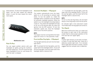
tered position. To return the headlights to low
beam, pull the lever toward the steering
wheel, or push the lever toward the instru-
ment panel.
Flash-To-Pass
You can signal another vehicle with your
headlights by lightly pulling the multifunc-
tion lever toward you. This will cause the high
beam headlights to turn on, and remain on,
until the lever is released.
Automatic Headlights — If Equipped
This system automatically turns the head-
lights on or off according to ambient light
levels. To turn the system on, rotate the
headlight switch clockwise to the last detent
for automatic headlight operation. When the
system is on, the headlight time delay feature
is also on. This means the headlights will stay
on for up to 90 seconds after you place the
ignition into the OFF position. To turn the
automatic system off, move the headlight
switch out of the AUTO position.
NOTE:
The engine must be running before the head-
lights will come on in the automatic mode.
Front And Rear Fog Lights — If Equipped
The fog light switches are built into the head-
light switch.
To activate the front fog lights, push the
upper half of the headlight switch. To turn off
the front fog lights, push the upper half of the
headlight switch a second time.
To activate the rear fog lights, push the
lower half of the headlight switch. To turn off
the rear fog lights, push the lower half of the
headlight switch a second time.
NOTE:
To turn on the rear fog lamps, the low beam
lamps or front fog lamps must first be active.
An indicator light in the instrument cluster
illuminates when the fog lights are turned on.
Turn Signals
Move the multifunction lever up or down and
the arrows on each side of the instrument
cluster flash to show proper operation of the
front and rear turn signal lights.
NOTE:
If either light remains on and does not flash,
or there is a very fast flash rate, check for a
defective outside light bulb. If an indicator
fails to light when the lever is moved, it would
suggest that the indicator bulb is defective.
Multifunction LeverGETTING TO KNOW YOUR VEHICLE
36
Page 39 of 348

Lane Change Assist — If Equipped
Tap the multifunction lever up or down once,
without moving beyond the detent, and the
turn signal (right or left) will flash three times
then automatically turn off.
Lights-On Reminder
If the headlights, parking lights, or cargo
lights are left on after the ignition is turned
OFF, a chime will sound when the driver’s
door is opened.
Headlight Leveling System — If Equipped
Your vehicle may be equipped with a head-
light leveling system. This system allows the
driver to maintain proper headlight beam
position with the road surface regardless of
vehicle load.
The control switch is located on the instru-
ment panel next to the dimmer control.
To operate, rotate the control switch until the
appropriate number, which corresponds to
the load listed on the chart, aligns with the
indicator line on the switch.
0/1Driver only, or driver and
front passenger.
2All seating positions occu-
pied, plus an evenly dis-
tributed load in the lug-
gage compartment. The
total weight of passengers
and load does not exceed
the maximum load capacity
of the vehicle.
3Driver, plus an evenly dis-
tributed load in the lug-
gage compartment. The
total weight of the driver
and load does not exceed
the maximum load capacity
of the vehicle.
WINDSHIELD WIPERS AND
WASHERS
The windshield wiper/washer control lever is
located on the right side of the steering col-
umn. The front wipers are operated by rotat-
ing a switch, located at the end of the lever.
Refer to “Rear Window Wiper/Washer” in this
section for further information on using the
rear window wiper/washer.
Windshield Wiper/Washer Lever
37
Page 40 of 348

Windshield Wiper Operation
Rotate the end of the lever upward to the
second detent past the intermittent settings
for low-speed wiper operation. Rotate the end
of the lever upward to the third detent past
the intermittent settings for high-speed wiper
operation.
CAUTION!
In cold weather, always turn off the wiper
switch and allow the wipers to return to the
park position before turning off the en-
gine. If the wiper switch is left on and the
wipers freeze to the windshield, damage to
the wiper motor may occur when the ve-
hicle is restarted.
NOTE:
Do not operate the windshield wipers with the
blades lifted from the windshield.
Intermittent Wiper System
Use the intermittent wiper when weather
conditions make a single wiping cycle, with a
variable pause between cycles, desirable. Ro-tate the end of the lever to the first detent
position for one of four intermittent settings.
The delay cycle can be set anywhere between
1 to 18 seconds.
NOTE:
The wiper delay times depend on vehicle
speed. If the vehicle is moving less than
10 mph (16 km/h), delay times will be
doubled.
Windshield Washers
To use the washer, pull the lever toward you
and hold while spray is desired. If the lever is
pulled while in the delay range, the wiper will
start and continue to operate for two or three
wipe cycles after the lever is released. Then,
the intermittent interval previously selected
will resume.
If the lever is pulled while in the off position,
the wipers will operate for two or three wipe
cycles. Then, the wipers will turn off.
WARNING!
Sudden loss of visibility through the wind-
shield could lead to a collision. You might
WARNING!
not see other vehicles or other obstacles.
To avoid sudden icing of the windshield
during freezing weather, warm the wind-
shield with the defroster before and during
windshield washer use.
Mist Feature
Push upward on the wiper lever to activate a
single wipe to clear off road mist or spray
from a passing vehicle. As long as the lever is
held up, the wipers will continue to operate.
NOTE:
The mist feature does not activate the washer
pump; therefore, no washer fluid will be
sprayed on the windshield. The wash func-
tion must be used in order to spray the
windshield with washer fluid.
Rear Window Wiper/Washer — If Equipped
A rotary switch on the center portion of the
windshield wiper/washer lever controls the
operation of the rear wiper/washer function.
GETTING TO KNOW YOUR VEHICLE
38