2018 Hyundai Sonata battery
[x] Cancel search: batteryPage 469 of 522

7-59
7
Maintenance
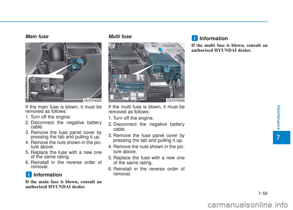
Main fuse
If the main fuse is blown, it must be
removed as follows:
1. Turn off the engine.
2. Disconnect the negative batterycable.
3. Remove the fuse panel cover by pressing the tab and pulling it up.
4. Remove the nuts shown in the pic- ture above.
5. Replace the fuse with a new one of the same rating.
6. Reinstall in the reverse order of removal.
Information
If the main fuse is blown, consult an
authorized HYUNDAI dealer.
Multi fuse
If the multi fuse is blown, it must be
removed as follows:
1. Turn off the engine.
2. Disconnect the negative battery
cable.
3. Remove the fuse panel cover by pressing the tab and pulling it up.
4. Remove the nuts shown in the pic- ture above.
5. Replace the fuse with a new one of the same rating.
6. Reinstall in the reverse order of removal.
Information
If the multi fuse is blown, consult an
authorized HYUNDAI dealer.
i
i
OLF074025OLF074026
Page 477 of 522
![Hyundai Sonata 2018 Owners Manual 7-67
7
Maintenance
Engine compartment main fuse panel - PCB Block
Fuse Name Fuse rating Protected Component
FUSE
2 VACUUM PUMP10A[G4KH/G4FJ] Vacuum Pump, Vacuum Switch
3 ECU10APCM/ECM
1 POWER OUTLET20 Hyundai Sonata 2018 Owners Manual 7-67
7
Maintenance
Engine compartment main fuse panel - PCB Block
Fuse Name Fuse rating Protected Component
FUSE
2 VACUUM PUMP10A[G4KH/G4FJ] Vacuum Pump, Vacuum Switch
3 ECU10APCM/ECM
1 POWER OUTLET20](/manual-img/35/16776/w960_16776-476.png)
7-67
7
Maintenance
Engine compartment main fuse panel - PCB Block
Fuse Name Fuse rating Protected Component
FUSE
2 VACUUM PUMP10A[G4KH/G4FJ] Vacuum Pump, Vacuum Switch
3 ECU10APCM/ECM
1 POWER OUTLET20AFront Cigarette Lighter & Power Outlet #2
FUEL PUMP20AFuel Pump Relay
HORN20AHorn Relay, ICM Relay Box (Burglar Alarm Horn Relay)
WIPER30AFront Wiper (Low) Relay, Front Wiper (High) Relay
2 TCU15ATransmission Range Switch, TCM (G4FJ-DCT)
3 ABS10AESC Module
2 POWER OUTLET20ARear Power Outlet
B/UP LAMP10ATransmission Range Switch, PCM (G4KJ/G4KH-A/T), TCM (G4FJ-DCT),
Electro Chromic Mirror, Rear Combination Lamp (IN) LH/RH
1 SENSOR15AOxygen Sensor (Up/Down)
2 SENSOR15A
Purge Control Solenoid Valve, Canister Close Valve, RCV Control Solenoid Valve,
Fuel Pump Relay, E/R Junction Block (Cooling Fan High Relay, Fuel Pump Relay),
[G4KJ/G4KH] Variable Intake Solenoid Valve, Oil Control Valve (Exhaust),
[G4FJ] Oil Control Valve #1/#2 (Intake/Exhaust)
1 ECU10APCM/ECM
1 TCU10APCM (G4KJ/G4KH-A/T), TCM (G4FJ-DCT)
1 ECU10APCM/ECM
IGN COIL20AIgnition Coil #1/#2/#3/#4
INJECTOR15ANot Used
AMS10ABattery Sensor
Page 480 of 522

7-70
Maintenance
Always handle them carefully, and avoid scratches and abrasions. If
the bulbs are lit, avoid contact with
liquids.
Never touch the glass with bare hands. Residual oil may cause the
bulb to overheat and burst when lit.
A bulb should be operated only when installed in a headlamp.
If a bulb becomes damaged or cracked, replace it immediately
and carefully dispose of it.
1. Open the hood.
2. Disconnect the negative batterycable.
3. Remove the headlamp bulb cover by turning it counterclockwise.
4. Disconnect the headlamp bulb socket-connector. 5. Unsnap the headlamp bulb retain-
ing wire by pressing the end and
pushing it upward.
6. Remove the bulb from the head- lamp assembly.
7. Install a new headlamp bulb and snap the headlamp bulb retaining
wire into position by aligning the
wire with the groove on the bulb.
8. Connect the headlamp bulb sock- et-connector.
9. Install the headlamp bulb cover by turning it clockwise.
Information
The headlamp aiming should be
adjusted after an accident or after the
headlamp assembly is reinstalled at an
authorized HYUNDAI dealer.
Headlamp (LED type)
If the light bulb does not operate, we
recommend that the system be
checked by an authorized HYUNDAI
dealer.
i
OLF077070
OLF077069
■Low beam
■High beam
Page 481 of 522

7-71
7
Maintenance
Turn signal lamp
1. Open the hood.
2. Disconnect the negative batterycable.
3. Remove the socket from the assembly by turning the socket
counterclockwise until the tabs on
the socket align with the slots on
the assembly.
4. Remove the bulb from the socket by pressing it in and rotating it
counterclockwise until the tabs on
the bulb align with the slots in the
socket. Pull the bulb out of the
socket. 5. Insert a new bulb by inserting it
into the socket and rotating it until
it locks into place.
6. Install the socket in the assembly by aligning the tabs on the socket
with the slots in the assembly.
7. Push the socket into the assembly and turn the socket clockwise.
Side marker
1. Open the hood.
2. Disconnect the negative batterycable.
3. Remove the socket from the assembly by turning the socket
counterclockwise until the tabs on
the socket align with the slots on
the assembly.
4. Remove the bulb from the socket by pulling out the bulb.
5. Insert a new bulb.
OLF077074OLF077052N
Page 496 of 522

7-86
Maintenance
Canister
Fuel vapors generated inside the fuel
tank are absorbed and stored in the
onboard canister. When the engine is
running, the fuel vapors absorbed in
the canister are drawn into the surge
tank through the purge control sole-
noid valve.
Purge Control Solenoid Valve(PCSV)
The purge control solenoid valve is
controlled by the Engine Control
Module (ECM); when the engine
coolant temperature is low during
idling, the PCSV closes so that evap-
orated fuel is not taken into the
engine. After the engine warms-up
during ordinary driving, the PCSV
opens to introduce evaporated fuel to
the engine.
3. Exhaust Emission Control System
The Exhaust Emission Control
System is a highly effective system
which controls exhaust emissions
while maintaining good vehicle per-
formance.
When the engine starts or fails to
start, excessive attempts to restart
the engine may cause damage to the
emission system.
Vehicle modifications
This vehicle should not be modi-
fied. Modification of your vehicle
could affect its performance, safety
or durability and may even violate
governmental safety and emis-
sions regulations.
In addition, damage or performance
problems resulting from any modifi-
cation may not be covered under
warranty.
If you use unauthorized electronic devices, it may cause the vehicle to
operate abnormally, wire damage,
battery discharge and fire. For your
safety, do not use unauthorized
electronic devices.
Engine exhaust (carbon monox-ide) precautions
Carbon monoxide can be present
with other exhaust fumes. If you
smell exhaust fumes of any kind in
your vehicle, drive with all the win-
dows fully open. Have your vehicle
checked and repaired immediately.
Engine exhaust gases contain
carbon monoxide (CO). Though
colorless and odorless, it is
dangerous and could be lethal if
inhaled. Follow the instructions
on this page to avoid CO poi-
soning.
WARNING
Page 514 of 522

I-2
Accessing your vehicle .....................................................3-4Immobilizer System ...................................................3-12
Remote Key ..................................................................3-4
Smart Key.....................................................................3-8\
Air Bag - Advanced Supplemental Restraint System.....2-45 Additional Safety Precautions ....................................2-67
Air Bag Warning Labels.............................................2-68
How Does the Air Bag System Operate? ...................2-51
Occupant Classification System (OCS) .....................2-56
SRS Care ....................................................................2-66\
What to Expect After an Air Bag Inflates ..................2-55
Where Are the Air Bags? ...........................................2-47
Why Didn't My Air Bag Go Off in a Collision? (Air bags are not designed to inflate in
every collision.).......................................................2-61
Air Cleaner......................................................................7-\
31 Filter Replacement .....................................................7-31
Air Conditioning System ..................................................8-6
Appearance Care .............................................................7-77 Exterior Care ..............................................................7-77
Interior Care ...............................................................7-82
Automatic climate control system ................................3-132 Automatic Heating and Air Conditioning ................3-133
Manual heating and Air Conditioning......................3-134
System Maintenance ................................................3-142
System Operation .....................................................3-140 Automatic emergency braking (AEB) ............................5-97
AEB warning message and system control................5-99
Limitation of the system ..........................................5-105
Sensor to detect the distance from the vehicle in front (front radar) ..............................................5-102
System malfunction ..................................................5-103
System setting and activation .....................................5-97
Battery ........................................................................\
.....7-37 Battery Recharging .....................................................7-38
For Best Battery Service ............................................7-38
Reset features .............................................................7-39
Before Driving ..................................................................5-4 Before Entering the Vehicle .........................................5-4
Before Starting .............................................................5-4
Blind Spot Detection System (BSD) ..............................5-89 BSD (Blind Spot Detection) / LCA (Lane Change Assist) .....................................5-90
RCTA (Rear Cross Traffic Alert) ...............................5-93
Brake Fluid .....................................................................7-2\
9 Checking the Brake Fluid Level ................................7-29
Index
A
B