2018 Hyundai Kona ESP
[x] Cancel search: ESPPage 411 of 497
7-4
Maintenance
MAINTENANCE SERVICES
You should exercise the utmost care
to prevent damage to your vehicle
and injury to yourself whenever per-
forming any maintenance or inspec-
tion procedures.
We recommend you have your vehi-
cle maintained and repaired by a
HYUNDAI authorised repairer. A
HYUNDAI authorised repairer meets
HYUNDAI’s high service quality
standards and receives technical
support from HYUNDAI in order to
provide you with a high level of serv-
ice satisfaction.
Owner’s responsibility
Maintenance service and record reten-
tion are the owner’s responsibility.
You should retain documents that
show proper maintenance has been
performed on your vehicle in accor-
dance with the scheduled mainte-
nance service charts shown on the
following pages. You need this infor-
mation to establish your compliance
with the servicing and maintenance
requirements of your vehicle war-
ranties.Detailed warranty information is pro-
vided in your Warranty Booklet.
Repairs and adjustments required as
a result of improper maintenance or
a lack of required maintenance are
not covered.
Owner maintenance precau-
tions
Inadequate, incomplete or insuffi-
cient servicing may result in opera-
tional problems with your vehicle that
could lead to vehicle damage, an
accident, or personal injury. This
chapter provides instructions only for
the maintenance items that are easy
to perform. Several procedures can
be done only by a HYUNDAI autho-
rised repairer with special tools.
Your vehicle should not be modified
in any way. Such modifications may
adversely affect the performance,
safety or durability of your vehicle
and may, in addition, violate condi-
tions of the limited warranties cover-
ing the vehicle.
.
Improper owner maintenance dur-
ing the warranty period may affect
warranty coverage. For details,
read the separate Warranty Booklet
provided with the vehicle. If you're
unsure about any servicing or
maintenance procedure, we rec-
ommend that the system be serv-
iced by a HYUNDAI authorised
repairer.
NOTICE
Page 441 of 497
7-34
Maintenance
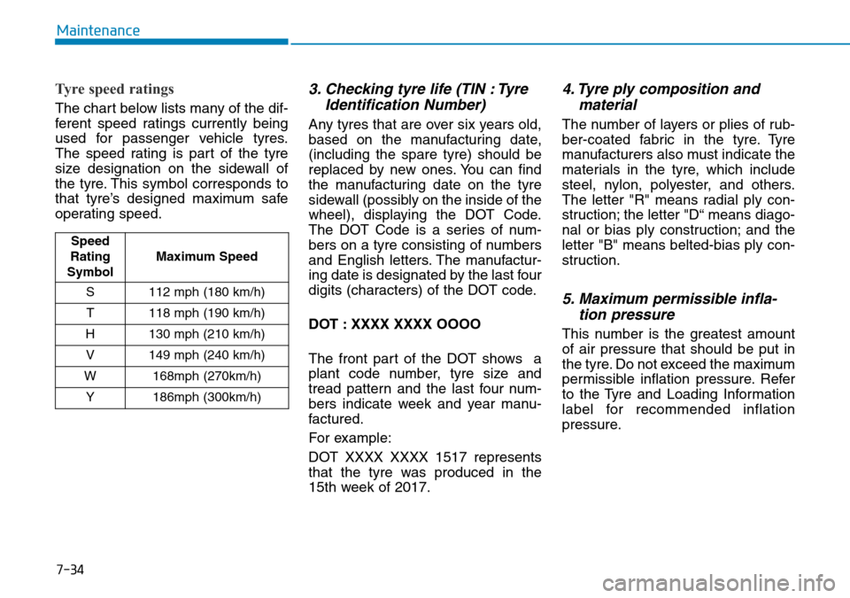
Tyre speed ratings
The chart below lists many of the dif-
ferent speed ratings currently being
used for passenger vehicle tyres.
The speed rating is part of the tyre
size designation on the sidewall of
the tyre. This symbol corresponds to
that tyre’s designed maximum safe
operating speed.
3. Checking tyre life (TIN : TyreIdentification Number)
Any tyres that are over six years old,
based on the manufacturing date,
(including the spare tyre) should be
replaced by new ones. You can find
the manufacturing date on the tyre
sidewall (possibly on the inside of the
wheel), displaying the DOT Code.
The DOT Code is a series of num-
bers on a tyre consisting of numbers
and English letters. The manufactur-
ing date is designated by the last four
digits (characters) of the DOT code.
DOT : XXXX XXXX OOOO
The front part of the DOT shows a
plant code number, tyre size and
tread pattern and the last four num-
bers indicate week and year manu-
factured.
For example:
DOT XXXX XXXX 1517 represents
that the tyre was produced in the
15th week of 2017.
4. Tyre ply composition andmaterial
The number of layers or plies of rub-
ber-coated fabric in the tyre. Tyre
manufacturers also must indicate the
materials in the tyre, which include
steel, nylon, polyester, and others.
The letter "R" means radial ply con-
struction; the letter "D“ means diago-
nal or bias ply construction; and the
letter "B" means belted-bias ply con-
struction.
5. Maximum permissible infla-tion pressure
This number is the greatest amount
of air pressure that should be put in
the tyre. Do not exceed the maximum
permissible inflation pressure. Refer
to the Tyre and Loading Information
label for recommended inflation
pressure.
Speed
Rating
Symbol Maximum Speed
S 112 mph (180 km/h) T 118 mph (190 km/h)
H 130 mph (210 km/h) V 149 mph (240 km/h)
W 168mph (270km/h) Y 186mph (300km/h)
Page 442 of 497
7-35
7
Maintenance
6. Maximum load rating
This number indicates the maximum
load in kilograms and pounds that
can be carried by the tyre. When
replacing the tyres on the vehicle,
always use a tyre that has the same
load rating as the factory installed
tyre.
7. Uniform tyre quality grading
Quality grades can be found where
applicable on the tyre sidewall
between tread shoulder and maxi-
mum section width.
For example:
TREAD WEAR 200
TRACTION AA
TEMPERATURE A
Tread wear
The tread wear grade is a compara-
tive rating based on the wear rate of
the tyre when tested under controlled
conditions on a specified govern-
ment test course. For example, a tyre
graded 150 would wear one-and-a-
half times (1½) as well on the gov-
ernment course as a tyre graded
100.
The relative performance of tyres
depends upon the actual conditions
of their use, however, and may
depart significantly from the norm
due to variations in driving habits,
service practices and differences in
road characteristics and climate.
These grades are molded on the
sidewalls of passenger vehicle tyres.
The tyres available as standard or
optional equipment on your vehicle
may vary with respect to grade.
Traction - AA, A, B & C
The traction grades, from highest to
lowest, are AA, A, B and C. Those
grades represent the tyre’s ability to
stop on wet pavement as measured
under controlled conditions on spec-
ified government test surfaces of
asphalt and concrete. A tyre marked
C may have poor traction perform-
ance.The traction grade assigned to
this tyre is based on straight-
ahead braking traction tests,
and does not include accelera-
tion, cornering, hydroplaning,
or peak traction characteristics.
WARNING
Page 450 of 497
7-43
7
Maintenance
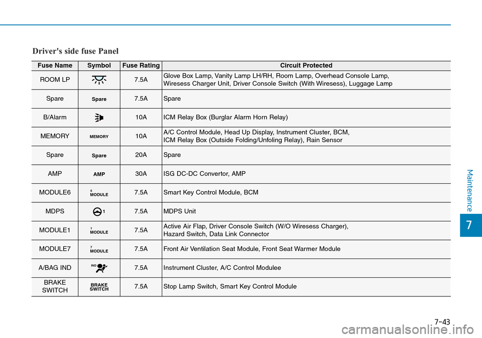
Driver's side fuse Panel
Fuse NameSymbolFuse RatingCircuit Protected
ROOM LP7.5AGlove Box Lamp, Vanity Lamp LH/RH, Room Lamp, Overhead Console Lamp,
Wiresess Charger Unit, Driver Console Switch (With Wiresess), Luggage Lamp
SpareSpare7.5ASpare
B/Alarm10AICM Relay Box (Burglar Alarm Horn Relay)
MEMORYMEMORY10AA/C Control Module, Head Up Display, Instrument Cluster, BCM,
ICM Relay Box (Outside Folding/Unfoling Relay), Rain Sensor
SpareSpare20ASpare
AMPAMP30AISG DC-DC Convertor, AMP
MODULE6MODULE67.5ASmart Key Control Module, BCM
MDPS17.5AMDPS Unit
MODULE1MODULE17.5AActive Air Flap, Driver Console Switch (W/O Wiresess Charger),
Hazard Switch, Data Link Connector
MODULE7MODULE77.5AFront Air Ventilation Seat Module, Front Seat Warmer Module
A/BAG INDIND7.5AInstrument Cluster, A/C Control Modulee
BRAKE
SWITCHBRAKE
SWITCH7.5AStop Lamp Switch, Smart Key Control Module
Page 451 of 497
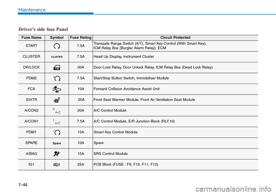
7-44
Maintenance
Driver's side fuse Panel
Fuse NameSymbolFuse RatingCircuit Protected
START7.5ATransaxle Range Switch (A/T), Smart Key Control (With Smart Key),
ICM Relay Box (Burglar Alarm Relay), ECM
CLUSTERCLUSTER7.5AHead Up Display, Instrument Cluster
DR/LOCK20ADoor Lock Relay, Door Unlock Relay, ICM Relay Box (Dead Lock Relay)
PDM227.5AStart/Stop Button Switch, Immobiliser Module
FCA10AForward Collision Avoidance Assist Unit
S/HTR20AFront Seat Warmer Module, Front Air Ventilation Seat Module
A/CON220AA/C Control Module
A/CON17.5AA/C Control Module, E/R Junction Block (RLY.10)
PDM1115ASmart Key Control Module
SPARESpare10ASpare
A/BAG15ASRS Control Module
IG1IG125APCB Block (FUSE : F9, F10, F11, F12)
Page 452 of 497
7-45
7
Maintenance
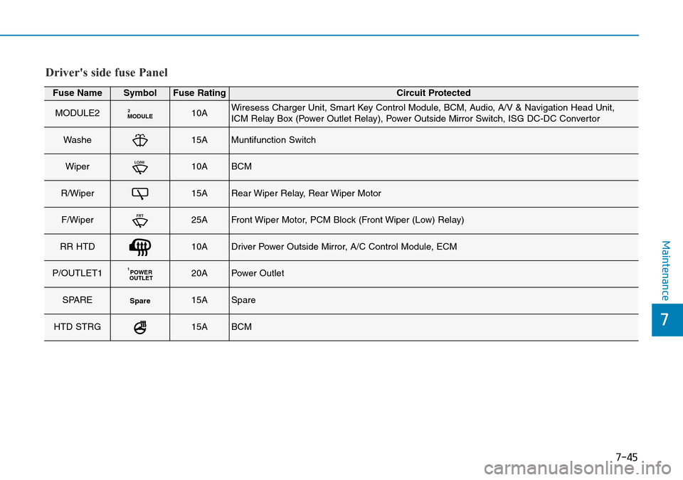
Driver's side fuse Panel
Fuse NameSymbolFuse RatingCircuit Protected
MODULE2MODULE210AWiresess Charger Unit, Smart Key Control Module, BCM, Audio, A/V & Navigation Head Unit,
ICM Relay Box (Power Outlet Relay), Power Outside Mirror Switch, ISG DC-DC Convertor
Washe15AMuntifunction Switch
WiperLO/HI10ABCM
R/Wiper15ARear Wiper Relay, Rear Wiper Motor
F/WiperFRT25AFront Wiper Motor, PCM Block (Front Wiper (Low) Relay)
RR HTD10ADriver Power Outside Mirror, A/C Control Module, ECM
P/OUTLET1POWER
OUTLET120APower Outlet
SPARESpare15ASpare
HTD STRG15ABCM
Page 461 of 497
7-54
Maintenance
LIGHT BULBS
Consult a HYUNDAI authorised
repairer to replace most vehicle light
bulbs. It is difficult to replace vehicle
light bulbs because other parts of the
vehicle must be removed before you
can get to the bulb. This is especially
true for removing the headlamp
assembly to get to the bulb(s).
Removing/installing the headlamp
assembly can result in damage to
the vehicle.Be sure to replace the burned-out
bulb with one of the same wattage
rating. Otherwise, it may cause
damage to the fuse or electrical
wiring system.
Information
After heavy driving rain or washing,
headlamp and tail lamp lenses could
appear frosty. This condition is caused
by the temperature difference between
the lamp inside and outside. This is
similar to the condensation on your
windows inside your vehicle when
raining and doesn’t indicate a problem
with your vehicle. If the water leaks
into the lamp bulb circuitry, we rec-
ommend that the system be checked
by a HYUNDAI authorised repairer.
Information
The headlamp aiming should be adjust-
ed after an accident or after the head-
lamp assembly is reinstalled at a
HYUNDAI authorised repairer.
Information - Traffic Change
The low beam light distribution is
asymmetric. If you go abroad to a coun-
try with opposite traffic direction, this
asymmetric part will dazzle oncoming
car driver. To prevent dazzle, ECE reg-
ulation demand several technical solu-
tions (ex. automatic change system,
adhesive sheet, down aiming). These
headlamps are designed not to dazzle
opposite drivers. So, you need not
change your headlamps in a country
with opposite traffic direction.i
i
i
NOTICE
Prior to working on a light, firmly
apply the parking brake, ensure
that the ignition switch is in the
LOCK/OFF position and turn off
the lights to avoid sudden move-
ment of the vehicle and burning
your fingers or receiving an elec-
tric shock.
WARNING
Page 466 of 497
7-59
7
Maintenance
5. Insert a new bulb by inserting itinto the socket and rotating it until
it locks into place.
6. Install the socket in the assembly by aligning the tabs on the socket
with the slots in the assembly.
7. Push the socket into the assembly and turn the socket clockwise.
Position lamp and daytime running
light
If the LED lamp does not operate, we
recommend that you have the vehicle
checked by a HYUNDAI authorised
repairer.
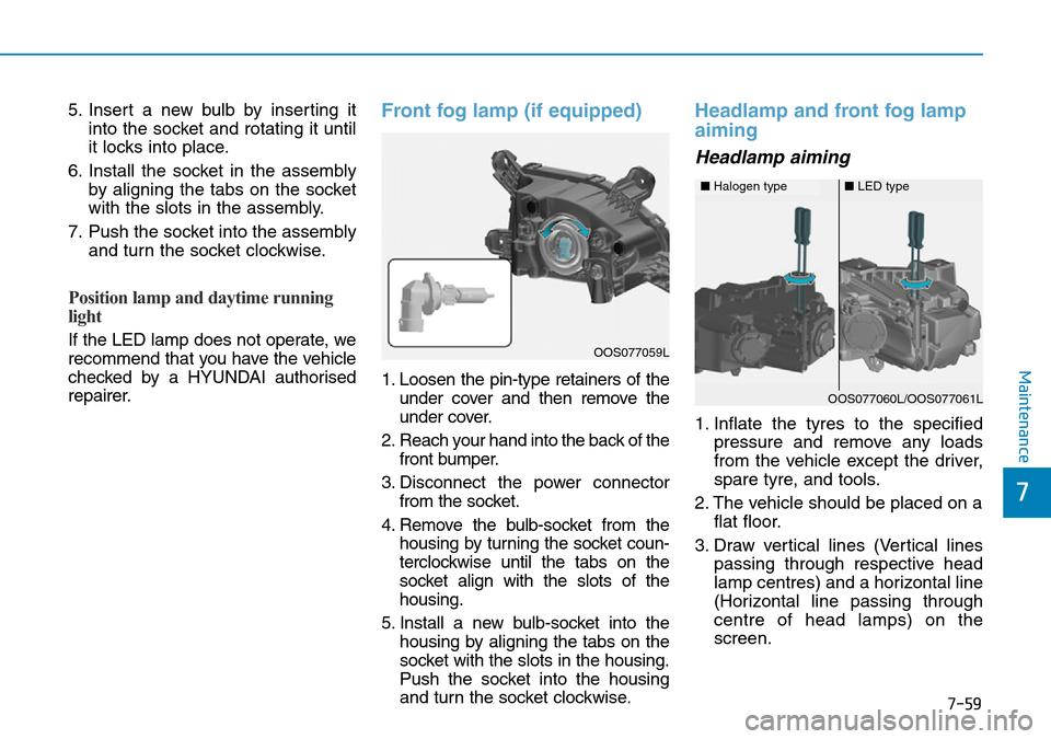
Front fog lamp (if equipped)
1. Loosen the pin-type retainers of theunder cover and then remove the
under cover.
2. Reach your hand into the back of the front bumper.
3. Disconnect the power connector from the socket.
4. Remove the bulb-socket from the housing by turning the socket coun-
terclockwise until the tabs on the
socket align with the slots of the
housing.
5. Install a new bulb-socket into the housing by aligning the tabs on the
socket with the slots in the housing.
Push the socket into the housing
and turn the socket clockwise.
Headlamp and front fog lamp
aiming
Headlamp aiming
1. Inflate the tyres to the specified pressure and remove any loads
from the vehicle except the driver,
spare tyre, and tools.
2. The vehicle should be placed on a flat floor.
3. Draw vertical lines (Vertical lines passing through respective head
lamp centres) and a horizontal line
(Horizontal line passing through
centre of head lamps) on the
screen.
OOS077059L
■Halogen type■LED type
OOS077060L/OOS077061L