2018 FORD F-550 service
[x] Cancel search: servicePage 216 of 660
POWER TAKE-OFF (If Equipped)
WARNING
Use of auxiliary equipment that
exceeds the maximum Power
Take-Off (PTO) load specified in the
Ford Truck Body Builders Layout Book can
adversely affect the performance of the
powertrain system. Refer to the Body
Builders Layout Book for instructions about
the appropriate installation of additional
equipment. Auxiliary equipment called power take-off,
or PTO, is often added to the engine or
transmission to operate utility equipment.
Examples include a wheel-lift for tow
trucks, cranes, tools for construction or tire
service, and pumping fluids. PTO
applications draw auxiliary horsepower
from the powertrain, often while the
vehicle is stationary. In this condition, there
is limited cooling air flow through the
radiator and around the vehicle that
normally occurs when a vehicle is moving.
The aftermarket PTO system installer,
having the most knowledge of the final
application, is responsible for determining
whether additional chassis heat protection
or powertrain cooling is required, and
alerting the user to the safe and proper
operation.
Ford Super Duty Vehicles are approved for
use as a stationary (including split shaft
capability) or mobile power source, within
limits and operating guidelines detailed in
the Ford Truck Body Builders Layout Book,
found at www.fleet.ford.com/truckbbas,
and through the Ford Truck Body Builders
Advisory Service.
213
Super Duty (TFE) Canada/United States of America, enUSA, Edition date: 201709, Second Printing Transmission
Page 218 of 660
For proper operation, make sure that each
hub is fully engaged and that both hub
locks are set to the same position (both
set to LOCK or both set to AUTO). To
engage LOCK, turn the hub locks
completely clockwise; to engage AUTO,
turn the hub locks completely
counterclockwise.
The ESOF 4WD system:
•
provides 4x4 High engagement and
disengagement while the vehicle is
moving.
• is operated by a rotary control located
on the instrument panel that allows
you select 4x2, 4x4 High or 4x4 Low
operation.
• uses auto-manual hub locks that can
be engaged and disengaged
automatically based on the 4x4 mode
selected.
• will increase fuel economy when used
in the hub lock's recommended AUTO
mode.
4WD Indicator Lights
Note: When a 4X4 system fault is present,
the system will typically remain in whichever
4X4 mode was selected prior to the fault
condition occurring. It will not default to 4X2
in all circumstances. When this warning is
displayed, have your vehicle serviced by an
authorized dealer.
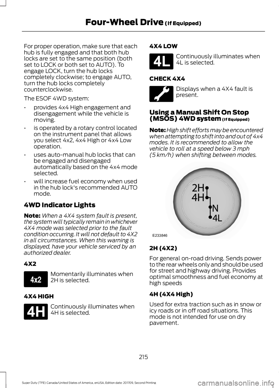
4X2 Momentarily illuminates when
2H is selected.
4X4 HIGH Continuously illuminates when
4H is selected. 4X4 LOW Continuously illuminates when
4L is selected.
CHECK 4X4 Displays when a 4X4 fault is
present.
Using a Manual Shift On Stop
(MSOS) 4WD system (If Equipped)
Note: High shift efforts may be encountered
when attempting to shift into and out of 4x4
modes. It is recommended to allow the
vehicle to roll at a speed below
3 mph
(5 km/h) when shifting between modes. 2H (4X2)
For general on-road driving. Sends power
to the rear wheels only and should be used
for street and highway driving. Provides
optimal smoothness and fuel economy at
high speeds
4H (4X4 High)
Used for extra traction such as in snow or
icy roads or in off road situations. This
mode is not intended for use on dry
pavement.
215
Super Duty (TFE) Canada/United States of America, enUSA, Edition date: 201709, Second Printing Four-Wheel Drive
(If Equipped)E163173 E181779 E181780 E233846
Page 230 of 660
HINTS ON DRIVING WITH
ANTI-LOCK BRAKES
The anti-lock braking system does not
eliminate the risks when:
•
You drive too closely to the vehicle in
front of you.
• Your vehicle is hydroplaning.
• You take corners too fast.
• The road surface is poor.
Note: If the system activates, the brake
pedal may pulse and may travel further.
Maintain pressure on the brake pedal. You
may also hear a noise from the system. This
is normal.
PARKING BRAKE WARNING
Always set the parking brake fully
and make sure the transmission is
placed in park (P). Failure to set the
parking brake and engage park could result
in vehicle roll-away, property damage or
bodily injury. Turn the ignition to the lock
position and remove the key whenever you
leave your vehicle. Apply the parking brake whenever your
vehicle is parked. Press the pedal
downward to set the parking brake. The
brake warning lamp in the instrument
cluster will illuminate and remains
illuminated until the parking brake is
released.
To release, pull the brake release lever
located at the lower left side of the
instrument panel. If you are parking your vehicle on a grade
or with a trailer, press and hold the brake
pedal down, then set the parking brake.
There may be a little vehicle movement as
the parking brake sets to hold the vehicle's
weight. This is normal and should be no
reason for concern. If needed, press and
hold the service brake pedal down, then
try reapplying the parking brake. Chock the
wheels if required. If the parking brake
cannot hold the weight of the vehicle, the
parking brake may need to be serviced or
the vehicle may be overloaded.
HILL START ASSIST
WARNINGS
The system does not replace the
parking brake. When you leave your
vehicle, always apply the parking
brake. You must remain in your vehicle
when the system turns on. At all
times, you are responsible for
controlling your vehicle, supervising the
system and intervening, if required. Failure
to take care may result in the loss of
control of your vehicle, serious personal
injury or death. The system will turn off if a
malfunction is apparent or if you rev
the engine excessively. Failure to
take care may result in the loss of control
of your vehicle, serious personal injury or
death. The system makes it easier to pull away
when your vehicle is on a slope without the
need to use the parking brake.
When the system is active, your vehicle
remains stationary on the slope for two to
three seconds after you release the brake
pedal. This allows time to move your foot
from the brake to the accelerator pedal.
The system releases the brakes
227
Super Duty (TFE) Canada/United States of America, enUSA, Edition date: 201709, Second Printing Brakes
Page 232 of 660
PRINCIPLE OF OPERATION
The traction control system helps avoid
drive wheel spin and loss of traction.
If your vehicle begins to slide, the system
applies the brakes to individual wheels
and, when needed, reduces engine power
at the same time. If the wheels spin when
accelerating on slippery or loose surfaces,
the system reduces engine power in order
to increase traction.
USING TRACTION CONTROL
WARNING
The stability and traction control
light illuminates steadily if the
system detects a failure. Make sure
you did not manually disable the traction
control system using the information
display controls or the switch. If the
stability control and traction control light
is still illuminating steadily, have the
system serviced by an authorized dealer
immediately. Operating your vehicle with
the traction control disabled could lead to
an increased risk of loss of vehicle control,
vehicle rollover, personal injury and death. The system automatically turns on each
time you switch the ignition on.
If your vehicle is stuck in mud or snow,
switching traction control off may be
beneficial as this allows the wheels to spin.
Note:
When you switch traction control off,
stability control remains fully active.
Note: For additional information on the
traction and stability control systems. See
Using Stability Control (page 231).
Switching the System Off
When you switch the system off or on, a
message appears in the information
display showing system status. Use the traction and stability control
switch on the instrument panel to switch
the system off or on.
The switch illuminates when traction
control is off.
When you place your vehicle into
four-wheel drive low mode the traction
control disables. Traction control resumes
full operation when you put your vehicle
back into two-wheel drive mode.
System Indicator Lights and
Messages
The stability and traction control
light:
• Temporarily illuminates on engine
start-up.
• Flashes when a driving condition
activates either of the systems.
• Illuminates if a problem occurs in either
of the systems. The stability and traction control
off light temporarily illuminates
on engine start-up and stays on
when you switch the traction control
system off.
229
Super Duty (TFE) Canada/United States of America, enUSA, Edition date: 201709, Second Printing Traction ControlE166706 E225465 E225466
Page 262 of 660

System Limitations
Cross Traffic Alert has its limitations;
situations such as severe weather
conditions or debris build-up on the sensor
area may limit vehicle detection and cause
false alerts.
The following are other situations that may
limit the Cross Traffic Alert performance:
•
Adjacently parked vehicles or objects
obstructing the sensors.
• Approaching vehicles passing at
speeds greater than 37 mph
(60 km/h).
• Driving in reverse faster than
7 mph
(12 km/h).
• Backing out of an angled parking spot.
False Alerts
Note: If your vehicle has a tow bar with a
factory equipped trailer tow module and it
is towing a trailer, the sensors will
automatically turn the Cross Traffic Alert
off. If your vehicle has a tow bar but no
factory equipped trailer tow module, it is
recommended to turn the Cross Traffic Alert
off manually. Operating Cross Traffic Alert
with a trailer attached will cause poor Cross
Traffic Alert performance.
Note: The system may illuminate the amber
alert indicator and sound the audible alert
during heavy rain even though no vehicle is
approaching from left or right.
There may be certain instances when there
is a false alert by the Cross Traffic Alert
system that illuminates the alert indicator
with no vehicle in the coverage zone. Some
amount of false alerts are normal; they are
temporary and self-correct. System Errors
If Cross Traffic Alert senses a problem with
the left or right sensor a message appears
in the display screen. See
Information
Messages (page 129).
Switching the System Off and On
Note: The Cross Traffic Alert switches on
whenever the ignition is switched on and
ready to provide appropriate alerts when
the transmission is in reverse (R). Cross
Traffic Alert will not remember the last
selected on or off setting.
You can temporarily switch Cross Traffic
Alert off in the information display. See
General Information
(page 113). When
you switch Cross Traffic Alert off, you do
not receive alerts and the display screen
shows a system off message.
You can also have Cross Traffic Alert
switched off permanently at an authorized
dealer. Once switched off permanently,
the system can only be switched back on
at an authorized dealer.
STEERING
Power Steering
To help prevent damage to the power
steering system:
• Never hold the steering wheel at its
furthest turning points (until it stops)
for more than three seconds when the
engine is running.
• Do not operate the vehicle with a low
power steering pump fluid level (below
the MIN mark on the reservoir).
• Some noise is normal during operation.
If excessive, check for low power
steering pump fluid level before
seeking service by your dealer.
259
Super Duty (TFE) Canada/United States of America, enUSA, Edition date: 201709, Second Printing Driving Aids
Page 263 of 660

•
Heavy or uneven efforts may be caused
by low power steering fluid. Check for
low power steering pump fluid level
before seeking service by your dealer.
• Do not fill the power steering pump
reservoir above the MAX mark on the
reservoir, as this may result in leaks
from the reservoir.
If the power steering system breaks down
(or if the engine is turned off), you can
steer the vehicle manually, but it takes
more effort.
If the steering wanders or pulls, check for:
• an improperly inflated tire
• uneven tire wear
• loose or worn suspension components
• loose or worn steering components
• improper vehicle alignment
If any steering components are serviced or
replaced, install new fasteners (many are
coated with thread adhesive or have
prevailing torque features which may not
be re-used). Never re-use a bolt or nut.
Torque fasteners to specifications.
A high crown in the road or high crosswinds
may also make the steering seem to
wander or pull.
Adaptive Steering (If Equipped)
Note: The adaptive steering system has
diagnostic checks that continuously monitor
the system. If a fault is detected a message
displays in the information display. If a red
warning message displays, stop your vehicle
as soon as it is safe to do so. The message
may clear if the fault is no longer present. If
an adaptive steering system warning
message appears each time you start your
vehicle, have the system checked as soon
as possible. The adaptive steering system continually
changes the steering ratio with changes to
vehicle speed, optimizing the steering
response in all conditions. The system also
changes when you switch on the
transmission tow/haul feature. When you
select the tow/haul button, the adaptive
steering system reduces vehicle sensitivity
to steering inputs at higher vehicle speeds,
while maintaining the ease of parking and
maneuverability at low speeds.
Note:
The adaptive steering system is
designed with a locking device. With the
lock engaged, the adaptive steering system
remains mechanically locked at a fixed
steering ratio. You may also notice a click
when you switch the vehicle on or after you
switch it off, as the lock disengages or
engages.
Note: If your vehicle loses electrical power
or detects a fault when you are driving, the
system automatically shuts down and you
retain normal steering function with a fixed
steering ratio. During this time it is possible
that the steering wheel may not be straight
when the vehicle is driving straight ahead.
In addition, the driver may notice that the
steering wheel angle required to steer the
vehicle may be different.
Note: During parking maneuvers, the
adaptive steering system balances the driver
work load for various steering wheel inputs
and vehicle loading conditions. Under
extreme operating conditions the system
locking device may engage. This strategy
prevents overheating and permanent
damage to the adaptive steering system.
Typical steering and driving maneuvers
allow the system to cool and return to
normal operation.
260
Super Duty (TFE) Canada/United States of America, enUSA, Edition date: 201709, Second Printing Driving Aids
Page 283 of 660
System is circling something beside the
sticker or system cannot find the sticker:
•
Make sure the rear camera is clean and
the sticker is clearly visible in the
camera image. Clean the camera and
sticker if necessary.
• The camera system uses the entered
measurements to help locate the
sticker. Inaccurate sticker
measurements degrade the system's
ability to locate the sticker. Verify the
measurements entered into the system
are accurate.
• Remove the incorrectly circled label or
decal if possible.
• If you cannot resolve the issue, a new
sticker location should be tried. The
new sticker location must meet the
requirements noted in step 3 of the
setup instructions. Only one sticker can
be placed on the trailer for correct
system function. The previous sticker
must be removed or covered so only
one sticker is visible to the camera.
Calibration
The system monitors various vehicle
parameters to ensure your vehicle is being
driven straight and the trailer straight
behind your vehicle. Any steering input or
trailer movement pauses the calibration.
For best results:
• Use a long, straight and smooth road
when attempting to calibrate.
• Drive straight forward.
• Drive between 4–24 mph
(6– 39 km/h).
System Operation
The following warnings or difficulties may
occur during feature operation. Tips to
resolve them are listed below. The system is not available:
•
The system relies on many
sub-systems in your vehicle to correctly
operate. If those sub-systems are not
correctly operating, the system may
not be available.
•Low battery voltage is one
condition which prevents the
system from operating. Please
make sure the battery is correctly
charged if the system is not
available.
• You may need to drive your vehicle
straight forward above
25 mph
(40 km/h) before the system is
available again.
• If the message still displays, take your
vehicle to an authorized dealer for
service.
Sticker lost:
• Check for the following if you receive
the lost sticker message when using
the system.
•Stop your vehicle as soon as the
message displays.
• Make sure the sticker is visible in
the rear view camera image.
• Clean the sticker and camera to
make sure they are unobstructed.
• Remove any items that may be
blocking the view of the sticker.
Depending on your trailer
configuration and any equipment
mounted to your trailer, it is
possible for the sticker to be
blocked from the view of the
camera as it rotates on the hitch
ball, but not be blocked during
setup. Remove the obstruction if
possible. It may be necessary to
280
Super Duty (TFE) Canada/United States of America, enUSA, Edition date: 201709, Second Printing Towing
Page 289 of 660
ESSENTIAL TOWING CHECKS
WARNING
Do not exceed the maximum vertical
load on the tow ball. Failure to follow
this instruction could result in the
loss of control of your vehicle, personal
injury or death. Follow these guidelines for safe towing:
•
Do not tow a trailer until you drive your
vehicle at least 1,000 mi (1,600 km).
• Consult your local motor vehicle laws
for towing a trailer.
• See the instructions included with
towing accessories for the proper
installation and adjustment
specifications.
• Service your vehicle more frequently if
you tow a trailer. See your scheduled
maintenance information.
See
Scheduled Maintenance (page 581).
• If you use a rental trailer, follow the
instructions the rental agency gives
you.
See
Load Limits in the Load Carrying
chapter for load specification terms found
on the tire label and Safety Compliance
label and instructions on calculating your
vehicle's load.
Vehicles with a diesel engine have an
engine braking feature.
See General
Information (page 225).
Remember to account for the trailer
tongue weight as part of your vehicle load
when calculating the total vehicle weight.
Some vehicles will have the ability to
modify trailer towing features. See
General Information
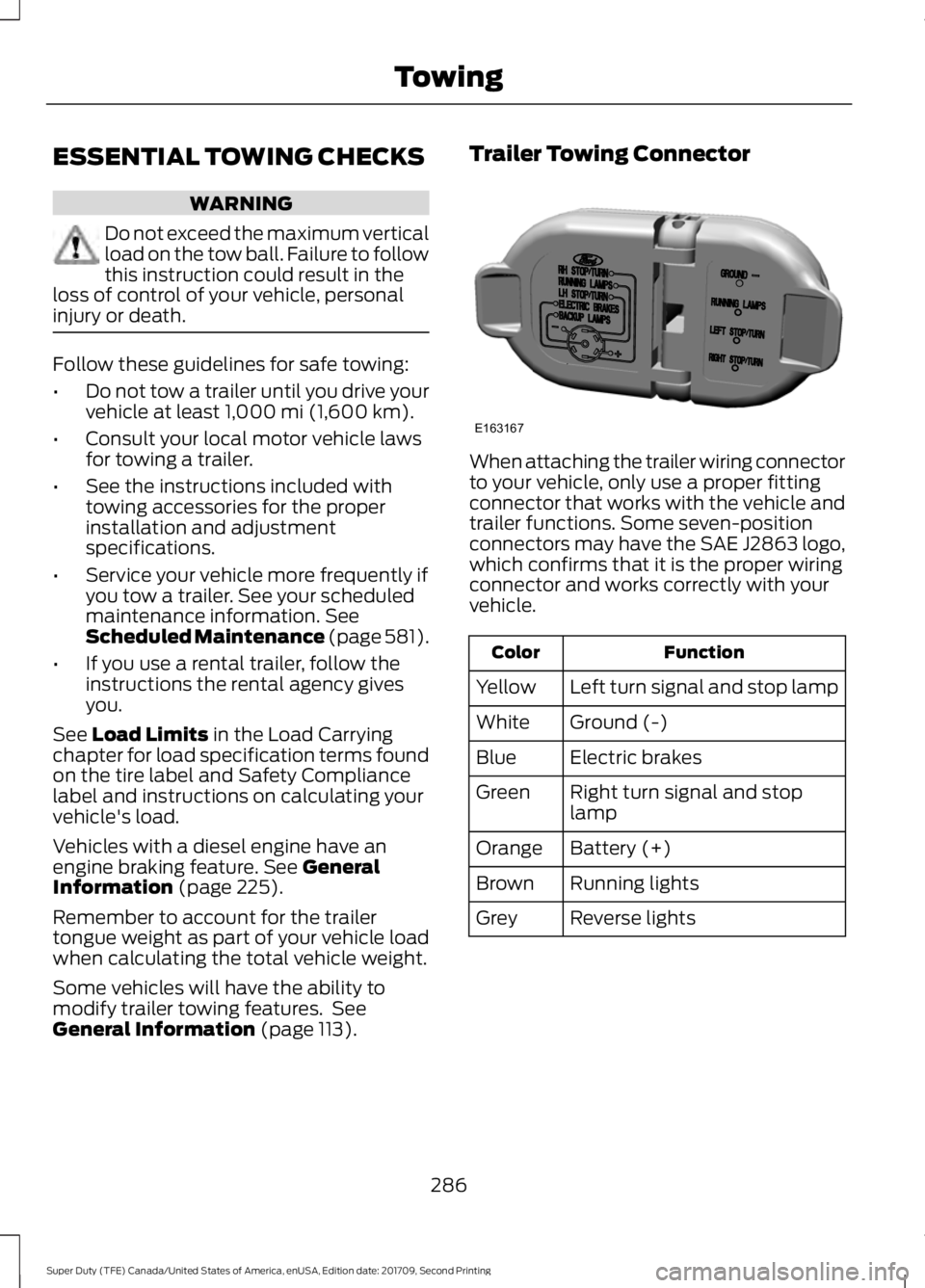
(page 113). Trailer Towing Connector
When attaching the trailer wiring connector
to your vehicle, only use a proper fitting
connector that works with the vehicle and
trailer functions. Some seven-position
connectors may have the SAE J2863 logo,
which confirms that it is the proper wiring
connector and works correctly with your
vehicle.
Function
Color
Left turn signal and stop lamp
Yellow
Ground (-)
White
Electric brakes
Blue
Right turn signal and stop
lamp
Green
Battery (+)
Orange
Running lights
Brown
Reverse lights
Grey
286
Super Duty (TFE) Canada/United States of America, enUSA, Edition date: 201709, Second Printing TowingE163167