2018 FORD F-450 clock
[x] Cancel search: clockPage 363 of 660

4. Remove the bulb by pulling it straight
out.
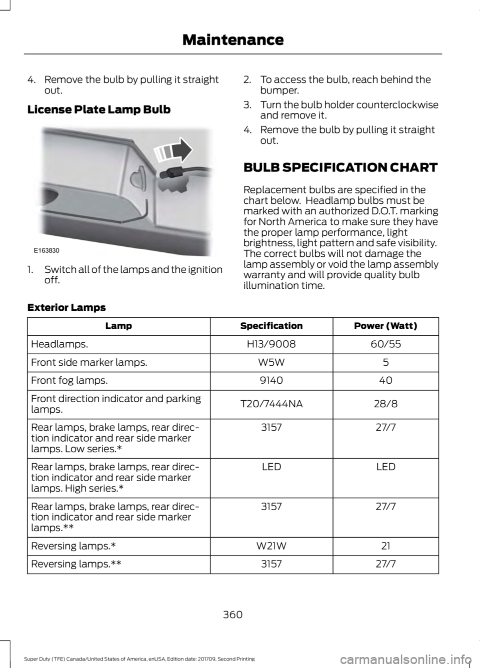
License Plate Lamp Bulb 1.
Switch all of the lamps and the ignition
off. 2. To access the bulb, reach behind the
bumper.
3. Turn the bulb holder counterclockwise
and remove it.
4. Remove the bulb by pulling it straight out.
BULB SPECIFICATION CHART
Replacement bulbs are specified in the
chart below. Headlamp bulbs must be
marked with an authorized D.O.T. marking
for North America to make sure they have
the proper lamp performance, light
brightness, light pattern and safe visibility.
The correct bulbs will not damage the
lamp assembly or void the lamp assembly
warranty and will provide quality bulb
illumination time.
Exterior Lamps Power (Watt)
Specification
Lamp
60/55
H13/9008
Headlamps.
5
W5W
Front side marker lamps.
40
9140
Front fog lamps.
28/8
T20/7444NA
Front direction indicator and parking
lamps.
27/7
3157
Rear lamps, brake lamps, rear direc-
tion indicator and rear side marker
lamps. Low series.*
LED
LED
Rear lamps, brake lamps, rear direc-
tion indicator and rear side marker
lamps. High series.*
27/7
3157
Rear lamps, brake lamps, rear direc-
tion indicator and rear side marker
lamps.**
21
W21W
Reversing lamps.*
27/7
3157
Reversing lamps.**
360
Super Duty (TFE) Canada/United States of America, enUSA, Edition date: 201709, Second Printing MaintenanceE163830
Page 370 of 660

3. Drain the diesel fuel conditioner
module. Turn the drain plug
counterclockwise until it stops. Do not
use any tools to loosen the drain plug.
Drain the filter, approximately 0.53 gal
(2 L), into an appropriate container.
Do not re-use the fuel drained from the
module. 4. Disconnect the electrical connector.
5. Fully loosen the bolts securing the
lower portion of the diesel fuel
conditioner module housing.
Note: Do not fully remove the bolts from
the lower portion of the diesel fuel
conditioner module housing.
6. Remove the lower portion of the diesel
fuel conditioner module housing.
367
Super Duty (TFE) Canada/United States of America, enUSA, Edition date: 201709, Second Printing Maintenance3
E226212 4
5
6
E226213
Page 371 of 660

7. Slide the filter element toward the
drain plug to disengage the securing
clips.
Installation
1. Slide the filter element into the housing
and fully engage the securing clips.
2. Install the lower portion of the housing.
Tighten the bolts until you feel a strong
resistance. Maximum torque 7 lb.ft
(9 Nm).
3. Connect the electrical connector.
4. Tighten the drain plug, turn it clockwise
until it stops and you feel a strong
resistance. Do not use any tools to
tighten the drain plug.
Engine-mounted Fuel Filter
Although the fuel system is not fully
pressurized when the vehicle is off, some
residual pressure may remain in the fuel
system since it can take some time for the
pressure to completely bleed off.
Therefore, we recommend you place an
absorbent cloth below the filter connectors
to absorb any fuel that may drain. The engine-mounted fuel filter is a plastic
disposable cartridge.
Removal
1.
Disconnect the fuel lines by squeezing
the connector tabs and pulling the lines
straight off. 2.
Rotate the filter fully counterclockwise
until the peg is at the far end of the slot.
3. Pull the filter straight up from the bracket and discard the filter.
368
Super Duty (TFE) Canada/United States of America, enUSA, Edition date: 201709, Second Printing Maintenance7
E226563 E226215
1 E226214
2
3
Page 372 of 660

Installation
1. Install the new filter into the filter
bracket. Turn the filter clockwise to
lock it in place.
2. Reconnect the fuel lines.
369
Super Duty (TFE) Canada/United States of America, enUSA, Edition date: 201709, Second Printing Maintenance
Page 408 of 660

•
To reduce the chances of interference
from another vehicle, perform the
system reset procedure at least three
feet (one meter) away from another
Ford Motor Company vehicle
undergoing the system reset procedure
at the same time.
• Do not wait more than two minutes
between resetting each tire sensor or
the system will time-out and the entire
procedure will have to be repeated on
all four wheels.
• A double horn will sound indicating the
need to repeat the procedure.
Performing the System Reset Procedure
(Single Rear Wheel)
Read the entire procedure before
attempting.
1. Drive the vehicle above 20 mph
(32 km/h) for at least two minutes,
then park in a safe location where you
can easily get to all four tires and have
access to an air pump.
2. Place the ignition in the off position and
keep the key in the ignition.
3. Cycle the ignition to the on position with the engine off.
4. Turn the hazard flashers on then off three times. You must accomplish this
within 10 seconds. If the reset mode
has been entered successfully, the horn
will sound once, the system indicator
will flash and a message is shown in
the information display. If this does not
occur, please try again starting at Step
2. If after repeated attempts to enter
the reset mode, the horn does not
sound, the system indicator does not
flash and no message is shown in the
information display, seek service from
your authorized dealer. 5. Train the tire pressure monitoring
system sensors in the tires using the
following system reset sequence
starting with the left front tire in the
following clockwise order: Left front
(driver's side front tire), Right front
(passenger's side front tire), Right rear
(passenger's side rear tire), Left rear
(driver's side rear tire).
6. Remove the valve cap from the valve stem on the left front tire. Decrease the
air pressure until the horn sounds.
Note: The single horn chirp confirms that
the sensor identification code has been
learned by the module for this position. If a
double horn is heard, the reset procedure
was unsuccessful, and you must repeat it.
7. Remove the valve cap from the valve stem on the right front tire. Decrease
the air pressure until the horn sounds.
8. Remove the valve cap from the valve stem on the right rear tire. Decrease the
air pressure until the horn sounds.
9. Remove the valve cap from the valve stem on the left rear tire. Decrease the
air pressure until the horn sounds.
Training is complete after the horn
sounds for the last tire trained (driver's
side rear tire), the system indicator
stops flashing, and a message is shown
in the information display.
10. Turn the ignition off. If two short horn
beeps are heard, the reset procedure
was unsuccessful and you must
repeat it. If after repeating the
procedure and two short beeps are
heard when the ignition is turned to
off, seek assistance from your
authorized dealer.
405
Super Duty (TFE) Canada/United States of America, enUSA, Edition date: 201709, Second Printing Wheels and Tires
Page 413 of 660

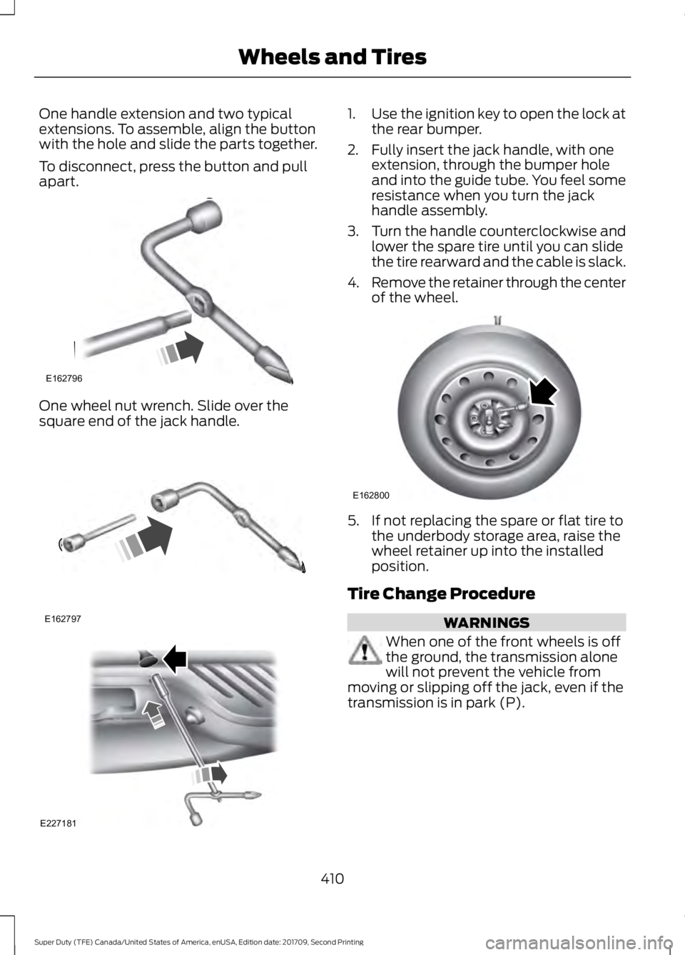
One handle extension and two typical
extensions. To assemble, align the button
with the hole and slide the parts together.
To disconnect, press the button and pull
apart.
One wheel nut wrench. Slide over the
square end of the jack handle. 1.
Use the ignition key to open the lock at
the rear bumper.
2. Fully insert the jack handle, with one extension, through the bumper hole
and into the guide tube. You feel some
resistance when you turn the jack
handle assembly.
3. Turn the handle counterclockwise and
lower the spare tire until you can slide
the tire rearward and the cable is slack.
4. Remove the retainer through the center
of the wheel. 5. If not replacing the spare or flat tire to
the underbody storage area, raise the
wheel retainer up into the installed
position.
Tire Change Procedure WARNINGS
When one of the front wheels is off
the ground, the transmission alone
will not prevent the vehicle from
moving or slipping off the jack, even if the
transmission is in park (P).
410
Super Duty (TFE) Canada/United States of America, enUSA, Edition date: 201709, Second Printing Wheels and TiresE162796 E162797 E227181 E162800
Page 414 of 660

WARNINGS
To help prevent your vehicle from
moving when changing a wheel, shift
the transmission into park (P), set
the parking brake and use an appropriate
block or wheel chock to secure the wheel
diagonally opposite to the wheel being
changed. For example, when changing the
front left wheel, place an appropriate block
or wheel chock on the right rear wheel. Do not get under a vehicle that is only
supported by a vehicle jack.
Do not attempt to change a tire on
the side of the vehicle close to
moving traffic. Pull far enough off the
road to avoid the danger of being hit when
operating the jack or changing the wheel. Always use the jack provided as
original equipment with your vehicle.
If using a jack other than the one
provided, make sure the jack capacity is
adequate for the vehicle weight, including
any vehicle cargo or modifications. If you
are unsure if the jack capacity is adequate,
contact the authorized dealer. Only use the spare wheel carrier to
stow the wheel provided with your
vehicle. Other wheel sizes could
cause the spare wheel carrier to fail if it
does not fit securely or is too heavy. Note:
Do not use impact tools or power
tools operating at over 200 RPM on the
spare wheel carrier winch, which may cause
it to malfunction and prevent a secure fit.
Override the winch at least three times
(there is an audible click each time) to make
sure the wheel and tire fit securely.
Note: Passengers should not remain in the
vehicle when the vehicle is being jacked.
Park on a level surface, set the parking
brake and activate the hazard flashers. 1.
Turn the engine off and block the wheel
that is diagonally opposite of the flat
tire using the wheel chock.
Note: Lock the manual hub on the wheel
if the vehicle is a 4x4.
2. Remove the jack, jack handle, lug wrench and spare tire from the
stowage locations.
3. Use the tip of the lug wrench to remove
any wheel trim.
4. Loosen each wheel lug nut ½ turn counterclockwise, but do not remove
them until the wheel is raised off the
ground.
Note: For vehicles with dual rear wheels,
insert the lug wrench extension into the lug
wrench to reach the lug nuts.
411
Super Duty (TFE) Canada/United States of America, enUSA, Edition date: 201709, Second Printing Wheels and TiresE142551
Page 416 of 660

Rear
Note:
Jack at the specified locations to
avoid damage to the vehicle.
Jacking the Vehicle 1. Turn the jack handle clockwise until
the wheel is completely off the ground
and high enough to install the spare
tire.
2. Remove the lug nuts with the lug wrench.
3. Replace the flat tire with the spare tire,
making sure the valve stem is facing
outward for all front wheels and single
rear wheel vehicles. If you are replacing
an inboard rear tire on dual rear wheel
vehicles, the valve stem must be facing
outward. If you are replacing the
outboard wheel, the valve stem must
be facing inward. Reinstall the lug nuts
until the wheel is snug against the hub.
Do not fully tighten the lug nuts until
the wheel has been lowered.
4. Lower the wheel by turning the jack handle counterclockwise.
5. Remove the jack and fully tighten the lug nuts in the order shown. See
Technical Specifications (page 418).
6. Stow the flat tire. See Stowing the flat or spare tire if the vehicle is equipped
with a spare tire carrier. 7. Stow the jack, jack handle and lug
wrench. Make sure the jack is securely
fastened so it does not rattle when
driving.
8. Unblock the wheels. 8-lug nut torque sequence
10-lug nut torque sequence
413
Super Duty (TFE) Canada/United States of America, enUSA, Edition date: 201709, Second Printing Wheels and TiresE162811 E161441
13
4
27
6
5
8 1
2
3
4
5
6
7 8
9
10
E169375 E162820