2018 FORD EXPEDITION light
[x] Cancel search: lightPage 285 of 571
For best results:
•
Use a long, straight, smooth and level
road when attempting to calibrate.
• Drive straight forward.
• Drive between 4 mph (6 km/h) and
24 mph (39 km/h).
System Operation
The following warnings or difficulties may
occur during feature operation. Tips to
resolve them are listed below.
The system is not available:
• The system relies on many
sub-systems in your vehicle to operate
correctly. If those sub-systems are not
operating correctly the system may not
be available.
• Low battery voltage is a condition
which prevents the system from
operating. Please make sure the
battery is correctly charged if the
system is not available.
• You may need to drive your vehicle
straight forward above
25 mph
(40 km/h) before the system is
available again.
• If the message still displays take your
vehicle to an authorized dealer for
service.
Sticker lost:
• If the system cannot initially find the
sticker, it may be necessary for you to
change the lighting conditions by
moving the vehicle and trailer or
waiting until conditions change.
• Check for the following if you receive
the lost sticker message while using
the system.
• Stop your vehicle as soon as the
message displays.
• Make sure the sticker is visible and the
pattern is discernable in the rear view
camera image. •
Clean the sticker and camera to make
sure they are unobstructed.
• Clean the lens with a soft, lint-free
cloth and water.
• Clean the sticker with isopropyl rubbing
alcohol sprayed directly onto the
sticker, and then wipe clean with a soft
cloth.
• Remove any items that may be
blocking the view of the sticker.
Depending on your trailer configuration
and any equipment mounted to your
trailer it is possible for the sticker to be
blocked from view of the camera as it
rotates on the hitch ball but not be
blocked during setup. Remove the
obstruction if possible. It is necessary
to remove the sticker from its current
location if the obstruction cannot be
cleared and place a new sticker that is
visible to the camera in all positions of
the trailer behind your vehicle.
• Placing the sticker on a surface angled
away from the vehicle reduces
performance. Use a drawbar that
positions the trailer level to the ground
when attached to vehicle. This typically
provides a level surface to mount the
sticker. Place the sticker on a bracket
or other object when no level surface
is available.
• Make sure the entire sticker is on a flat
surface that is completely visible to the
camera. Do not fold the sticker over an
edge on the trailer frame. This can
degrade performance.
• Shadows on the sticker may effect
tracking performance under some
lighting conditions. Moving the sticker
to another location within the allowed
placement area may improve
performance. Use the change sticker
option in your Towing menu if you
move the sticker.
282
Expedition (TB8) Canada/United States of America, enUSA, Edition date: 201708, Third-Printing- Towing
Page 288 of 571
This feature applies your vehicle brakes at
individual wheels and, if necessary, reduces
engine power. If the trailer begins to sway,
the stability control light flashes and the
message TRAILER SWAY REDUCE
SPEED appears in the information display.
The first thing to do is slow your vehicle
down, then pull safely to the side of the
road and check for proper tongue load and
trailer load distribution. See Towing (page
274
).
RECOMMENDED TOWING
WEIGHTS
Note: Do not exceed the trailer
weight for your vehicle
configuration listed in the chart
below.
Note: Make sure to take into
consideration trailer frontal area.
Do not exceed 36.5 feet² (3.39
meters²) if your vehicle is equipped
with the standard towing package,
or 60 feet² (5.57 meters²) if your
vehicle is equipped with the
optional heavy duty package.
Note: Exceeding this limitation
may significantly reduce the
performance of your towing
vehicle. Selecting a trailer with a
low aerodynamic drag and rounded
front design helps optimize
performance and fuel economy.
Note: For high altitude operation,
reduce the gross combined weight
by 2% per
1,000 ft (300 m)
starting at the 1,000 ft (300 m)
elevation point. Note:
Certain states require
electric trailer brakes for trailers
over a specified weight. Be sure to
check state regulations for this
specified weight. The maximum
trailer weights listed may be limited
to this specified weight, as the
vehicle ’s electrical system may not
include the wiring connector
needed to activate electric trailer
brakes.
Your vehicle may tow a trailer
provided the maximum trailer
weight is less than or equal to the
maximum trailer weight listed for
your vehicle configuration on the
following chart.
To calculate the maximum loaded
trailer weight for your vehicle:
1. Start with the gross combined weight rating for your vehicle
model and axle ratio. See the
following chart.
2. Subtract all of the following
that apply to your vehicle:
•Vehicle curb weight.
• Hitch hardware weight, such
as a draw bar, ball, locks or
weight distributing.
• Driver weight.
• Passenger weight.
• Payload, cargo and luggage
weight.
• Aftermarket equipment
weight.
3. This equals the maximum
loaded trailer weight for this
combination.
285
Expedition (TB8) Canada/United States of America, enUSA, Edition date: 201708, Third-Printing- Towing
Page 290 of 571
ESSENTIAL TOWING CHECKS
Follow these guidelines for safe towing:
•
Do not tow a trailer until you drive your
vehicle at least 1,000 mi (1,600 km).
• Consult your local motor vehicle laws
for towing a trailer.
• See the instructions included with
towing accessories for the proper
installation and adjustment
specifications.
• Service your vehicle more frequently if
you tow a trailer. See your scheduled
maintenance information.
• If you use a rental trailer, follow the
instructions the rental agency gives
you.
For load specification terms found on the
tire label and Safety Compliance label and
instructions on calculating your vehicle's
load,
See Load Limit (page 268).
Remember to account for the trailer
tongue weight as part of your vehicle load
when calculating the total vehicle weight.
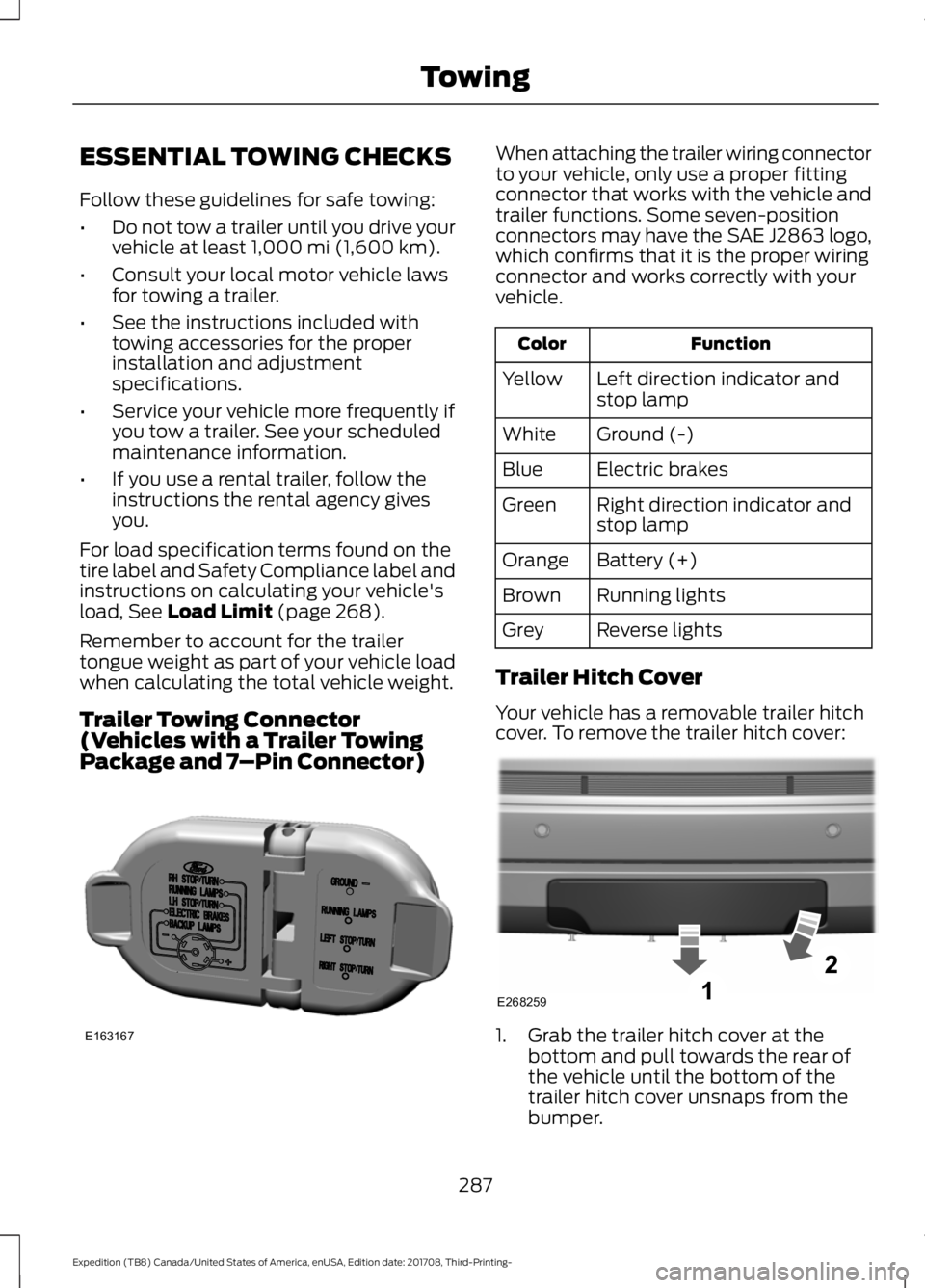
Trailer Towing Connector
(Vehicles with a Trailer Towing
Package and 7 –Pin Connector) When attaching the trailer wiring connector
to your vehicle, only use a proper fitting
connector that works with the vehicle and
trailer functions. Some seven-position
connectors may have the SAE J2863 logo,
which confirms that it is the proper wiring
connector and works correctly with your
vehicle.
Function
Color
Left direction indicator and
stop lamp
Yellow
Ground (-)
White
Electric brakes
Blue
Right direction indicator and
stop lamp
Green
Battery (+)
Orange
Running lights
Brown
Reverse lights
Grey
Trailer Hitch Cover
Your vehicle has a removable trailer hitch
cover. To remove the trailer hitch cover: 1. Grab the trailer hitch cover at the
bottom and pull towards the rear of
the vehicle until the bottom of the
trailer hitch cover unsnaps from the
bumper.
287
Expedition (TB8) Canada/United States of America, enUSA, Edition date: 201708, Third-Printing- TowingE163167 E268259
Page 292 of 571
Weight-distributing Hitch
WARNING: Do not adjust the
spring bars so that your vehicle's rear
bumper is higher than before attaching
the trailer. Doing so will defeat the
function of the weight-distributing hitch,
which may cause unpredictable
handling, and could result in serious
personal injury.
When hooking-up a trailer using a
weight-distributing hitch, always use the
following procedure:
1. Park the loaded vehicle, without the trailer, on a level surface.
2. Measure the height to the top of your vehicle's front wheel opening on the
fender. This is H1.
3. Attach the loaded trailer to your vehicle
without the weight-distributing bars
connected.
4. Measure the height to the top of your vehicle's front wheel opening on the
fender a second time. This is H2.
5. Install and adjust the tension in the weight-distributing bars so that the
height of your vehicle's front wheel
opening on the fender is approximately
half the way down from H2, toward H1.
6. Check that the trailer is level or slightly
nose down toward your vehicle. If not,
adjust the ball height accordingly and
repeat steps 2-6.
When the trailer is level or slightly nose
down toward the vehicle:
• Lock the bar tension adjuster in place.
• Check that the trailer tongue securely
attaches and locks onto the hitch.
• Install safety chains, lighting, and trailer
brake controls as required by law or the
trailer manufacturer. Safety Chains
Note:
Do not attach safety chains to the
bumper. Always connect the safety chains
to the frame or hook retainers of your trailer
hitch.
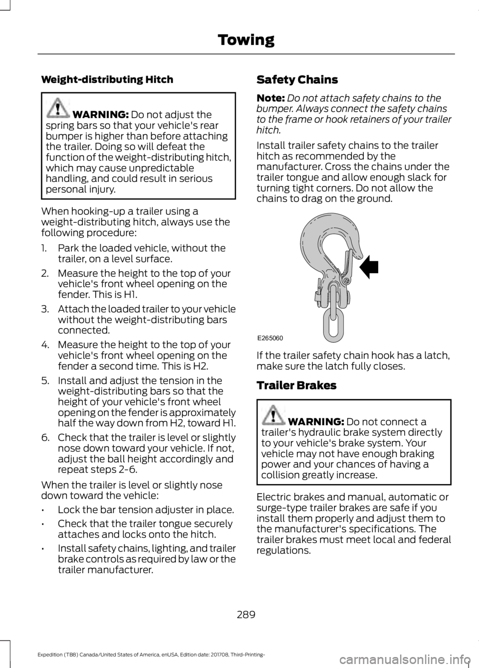
Install trailer safety chains to the trailer
hitch as recommended by the
manufacturer. Cross the chains under the
trailer tongue and allow enough slack for
turning tight corners. Do not allow the
chains to drag on the ground. If the trailer safety chain hook has a latch,
make sure the latch fully closes.
Trailer Brakes
WARNING:
Do not connect a
trailer's hydraulic brake system directly
to your vehicle's brake system. Your
vehicle may not have enough braking
power and your chances of having a
collision greatly increase.
Electric brakes and manual, automatic or
surge-type trailer brakes are safe if you
install them properly and adjust them to
the manufacturer's specifications. The
trailer brakes must meet local and federal
regulations.
289
Expedition (TB8) Canada/United States of America, enUSA, Edition date: 201708, Third-Printing- TowingE265060
Page 295 of 571

between the trailer brake controller and
the 7-pin connector at the bumper. If the
message only displays with a trailer
connected, the problem is with the trailer
wiring. Consult your trailer dealer for
assistance. This can be a short to ground
such as a chaffed wire, short to voltage
such as a pulled pin on trailer emergency
breakaway battery, or the trailer brakes
may be drawing too much current.
Points to Remember
Note:
Do not attempt removal of the trailer
brake controller without consulting the
Workshop Manual. Damage to the unit may
result.
• Adjust gain setting before using the
trailer brake controller for the first time.
• Adjust gain setting, using the procedure
above, whenever road, weather and
trailer or vehicle loading conditions
change from when the gain was initially
set.
• Only use the manual control lever for
proper adjustment of the gain during
trailer setup. Misuse, such as
application during trailer sway, could
cause instability of trailer or tow
vehicle.
• Avoid towing in adverse weather
conditions. The trailer brake controller
does not provide anti-lock control of
the trailer wheels. Trailer wheels can
lock up on slippery surfaces, resulting
in reduced stability of trailer and tow
vehicle.
• The trailer brake controller is equipped
with a feature that reduces output at
vehicle speeds below 11 mph (18 km/h)
so trailer and vehicle braking is not jerky
or harsh. This feature is only available
when applying the brakes using your
vehicle's brake pedal, not the
controller. •
The controller interacts with the brake
control system and powertrain control
system of your vehicle to provide the
best performance on different road
conditions.
• Your vehicle's brake system and the
trailer brake system work
independently of each other. Changing
the gain setting on the controller does
not affect the operation of your
vehicle's brakes whether you attach a
trailer or not.
• When you switch the engine off, the
controller output is disabled and the
display and module shut down. The
controller module and display turn on
when you switch the ignition on.
• The trailer brake controller is only a
factory-installed or dealer-installed
item. Ford is not responsible for
warranty or performance of the
controller due to misuse or customer
installation.
Trailer Lamps WARNING: Never connect any
trailer lamp wiring to the vehicle's tail
lamp wiring; this may damage the
electrical system resulting in fire. Contact
your authorized dealer as soon as
possible for assistance in proper trailer
tow wiring installation. Additional
electrical equipment may be required.
Trailer lamps are required on most towed
vehicles. Make sure all running lights, brake
lights, direction indicators and hazard lights
are working.
292
Expedition (TB8) Canada/United States of America, enUSA, Edition date: 201708, Third-Printing- Towing
Page 299 of 571
Note:
If your vehicle has intelligent access,
you can keep the vehicle on when switching
the engine off by pressing the
START/STOP button two times slowly
without pressing the brake pedal.
3. Press and hold the brake pedal.
4. Shift the transmission out of neutral (N) and into park (P).
5. Release the brake pedal.
Note: If completed successfully, the
instrument cluster displays
4X2, and
Neutral Tow Disabled.
Note: If the indicator light and message do
not display, you must perform the procedure
again from the beginning.
Note: You may hear an audible noise as the
transfer case shifts out of its neutral
position. This is normal.
Note: If
Shift Delayed Pull Forward
appears in the instrument cluster, transfer
case gear tooth blockage is present. See the
instructions after this section.
6. Apply the parking brake, then disconnect your vehicle from the tow
vehicle.
7. Release the parking brake, start the engine and shift the transmission to
drive (D) to make sure the transfer
case is out neutral (N).
8. If the transfer case does not successfully shift out of neutral (N),
set the parking brake until you can have
your vehicle serviced.
Resolving the
Shift Delayed Pull
Forward Message
If the instrument cluster displays
Shift
Delayed Pull Forward, perform the
following:
1. Press and hold the brake pedal.
2. Put the transmission into neutral (N), then start the engine. 3. With the engine running, shift the
transmission to drive (D) and let the
vehicle roll forward up to
3 ft (1 m). You
may hear an audible noise as the
transfer case shifts out of its neutral
position. This is normal.
4. Make sure the instrument cluster displays
Neutral Tow Disabled.
296
Expedition (TB8) Canada/United States of America, enUSA, Edition date: 201708, Third-Printing- Towing
Page 301 of 571
•
Do not warm up your vehicle on cold
mornings.
• Reduce the use of air conditioning and
heat.
• Avoid using speed control in hilly
terrain.
• Do not rest your foot on the brake
pedal while driving.
• Avoid carrying unnecessary weight.
• Avoid adding particular accessories to
your vehicle (e.g. bug deflectors,
rollbars/light bars, running boards, ski
racks).
• Avoid driving with the wheels out of
alignment.
DRIVING THROUGH WATER WARNING: Do not drive through
flowing or deep water as you may lose
control of your vehicle.
Note: Driving through standing water can
cause vehicle damage.
Note: Engine damage can occur if water
enters the air filter.
Before driving through standing water,
check the depth. Never drive through water
that is higher than the bottom of the wheel
hubs. When driving through standing water, drive
very slowly and do not stop your vehicle.
Your brake performance and traction may
be limited. After driving through water and
as soon as it is safe to do so:
•
Lightly press the brake pedal to dry the
brakes and to check that they work.
• Check that the horn works.
• Check that the exterior lights work.
• Turn the steering wheel to check that
the steering power assist works.
FLOOR MATS WARNING:
Use a floor mat
designed to fit the footwell of your
vehicle that does not obstruct the pedal
area. Failure to follow this instruction
could result in the loss of control of your
vehicle, personal injury or death. WARNING:
Pedals that cannot
move freely can cause loss of vehicle
control and increase the risk of serious
personal injury.
298
Expedition (TB8) Canada/United States of America, enUSA, Edition date: 201708, Third-Printing- Driving HintsE176913
Page 305 of 571
If your vehicle has a key system:
1. Switch off the ignition.
2. Switch to start position.
3. Switch off the ignition.
4.
Switch on the ignition to re-enable the
fuel pump.
5. If the vehicle does not start, repeat steps 1 through 4.
If your vehicle has a push button start
system:
1. Press START/STOP to switch off your
vehicle.
2. Press the brake pedal and START/STOP
to switch on your
vehicle.
3. Remove your foot from the brake pedal
and press
START/STOP to switch off
your vehicle.
4. You can attempt to start the vehicle by pressing the brake pedal and
START/STOP
, or press START/STOP
without pressing the brake pedal.
5. If the vehicle does not start, repeat steps 1 through 4.
JUMP STARTING THE VEHICLE WARNING:
Batteries normally
produce explosive gases which can
cause personal injury. Therefore, do not
allow flames, sparks or lighted
substances to come near the battery.
When working near the battery, always
shield your face and protect your eyes.
Always provide correct ventilation. WARNING:
Keep batteries out of
reach of children. Batteries contain
sulfuric acid. Avoid contact with skin,
eyes or clothing. Shield your eyes when
working near the battery to protect
against possible splashing of acid
solution. In case of acid contact with skin
or eyes, flush immediately with water for
a minimum of 15 minutes and get prompt
medical attention. If acid is swallowed,
call a physician immediately. WARNING:
Use only adequately
sized cables with insulated clamps.
Preparing Your Vehicle
Do not attempt to push-start your
automatic transmission vehicle.
Note: Attempting to push-start a vehicle
with an automatic transmission may cause
transmission damage.
Note: Use only a 12-volt supply to start your
vehicle.
Note: Do not disconnect the battery of the
disabled vehicle as this could damage the
vehicle electrical system.
Park the booster vehicle close to the hood
of the disabled vehicle, making sure the
two vehicles do not touch.
Connecting the Jumper Cables WARNING:
Do not attach the
cables to fuel lines, engine rocker covers,
the intake manifold or electrical
components as grounding points. Stay
clear of moving parts. To avoid reverse
polarity connections, make sure that you
correctly identify the positive (+) and
negative (-) terminals on both the
disabled and booster vehicles before
connecting the cables.
302
Expedition (TB8) Canada/United States of America, enUSA, Edition date: 201708, Third-Printing- Roadside Emergencies