2018 FORD E-350 ignition
[x] Cancel search: ignitionPage 94 of 323

•
You take corners too fast.
• The road surface is poor.
Note: If the system activates, the brake
pedal may pulse and may travel further.
Maintain pressure on the brake pedal. You
may also hear a noise from the system. This
is normal.
PARKING BRAKE WARNING
Always set the parking brake fully
and make sure the transmission
selector lever is placed in park (P).
Failure to set the parking brake and engage
park could result in vehicle roll-away,
property damage or bodily injury. Turn the
ignition to the lock position and remove
the key whenever you leave your vehicle. Apply the parking brake whenever your
vehicle is parked.
•
For vehicles equipped with a foot
operated parking brake, press the pedal
downward to set the parking brake.
• For vehicle equipped with a hand
operated parking brake, pull the
parking brake lever up to set the
parking brake. The brake warning lamp in the
instrument cluster illuminates
when the ignition is turned on
and the parking brake is applied.
The parking brake is not recommended to
stop a moving vehicle. However, if the
normal brakes fail, the parking brake can
be used to stop your vehicle in an
emergency. Your vehicle's stopping
distance will increase greatly and the
handling of your vehicle will be adversely
affected. To release the parking brake:
•
For vehicles equipped with a foot
operated parking brake, pull the
parking brake release lever.
• For vehicles equipped with a hand
operated parking brake, push the
parking brake lever down.
91
E-Series (TE4) Canada/United States of America, enUSA, Edition date: 201712, Second Printing BrakesE144522
Page 95 of 323

PRINCIPLE OF OPERATION
The traction control system helps avoid
drive wheel spin and loss of traction.
If your vehicle begins to slide, the system
applies the brakes to individual wheels
and, when needed, reduces engine power
at the same time. If the wheels spin when
accelerating on slippery or loose surfaces,
the system reduces engine power in order
to increase traction.
USING TRACTION CONTROL
WARNING
The traction control light illuminates
steadily if a failure is detected in the
system. Verify that the traction
control system was not manually disabled
using the switch. If the traction control light
is still illuminating steadily, have the
system serviced by an authorized dealer
immediately. Operating your vehicle with
traction control disabled could lead to an
increased risk of loss of vehicle control,
vehicle rollover, personal injury and death. The system automatically turns on each
time you switch the ignition on.
If your vehicle is stuck in mud or snow,
switching traction control off may be
beneficial as this allows the wheels to spin.
Switching the System Off
The switch for the traction
control system is located on the
instrument panel.
When you switch the system off, an
illuminated icon appears on the instrument
cluster.
Use the switch again to return the traction
control system to normal operation. System Indicator Lights and
Messages The traction control light
temporarily illuminates on
engine start-up and flashes
when a driving condition activates the
system. The traction control off light
temporarily illuminates on
engine start-up and stays on:
• When you switch the traction control
system off.
• If a problem occurs in the system.
92
E-Series (TE4) Canada/United States of America, enUSA, Edition date: 201712, Second Printing Traction Control (If Equipped)E194301 E138639 E194301
Page 98 of 323

PRINCIPLE OF OPERATION
Cruise control lets you maintain a set
speed without keeping your foot on the
accelerator pedal. You can use cruise
control when your vehicle speed is greater
than 20 mph (30 km/h).
USING CRUISE CONTROL
(If
Equipped) WARNINGS
Do not use cruise control on winding
roads, in heavy traffic or when the
road surface is slippery. This could
result in loss of vehicle control, serious
injury or death. When you are going downhill, your
vehicle speed could increase above
the set speed. The system does not
apply the brakes. To help the system to maintain the set
speed when going downhill, downshift to
a lower gear.
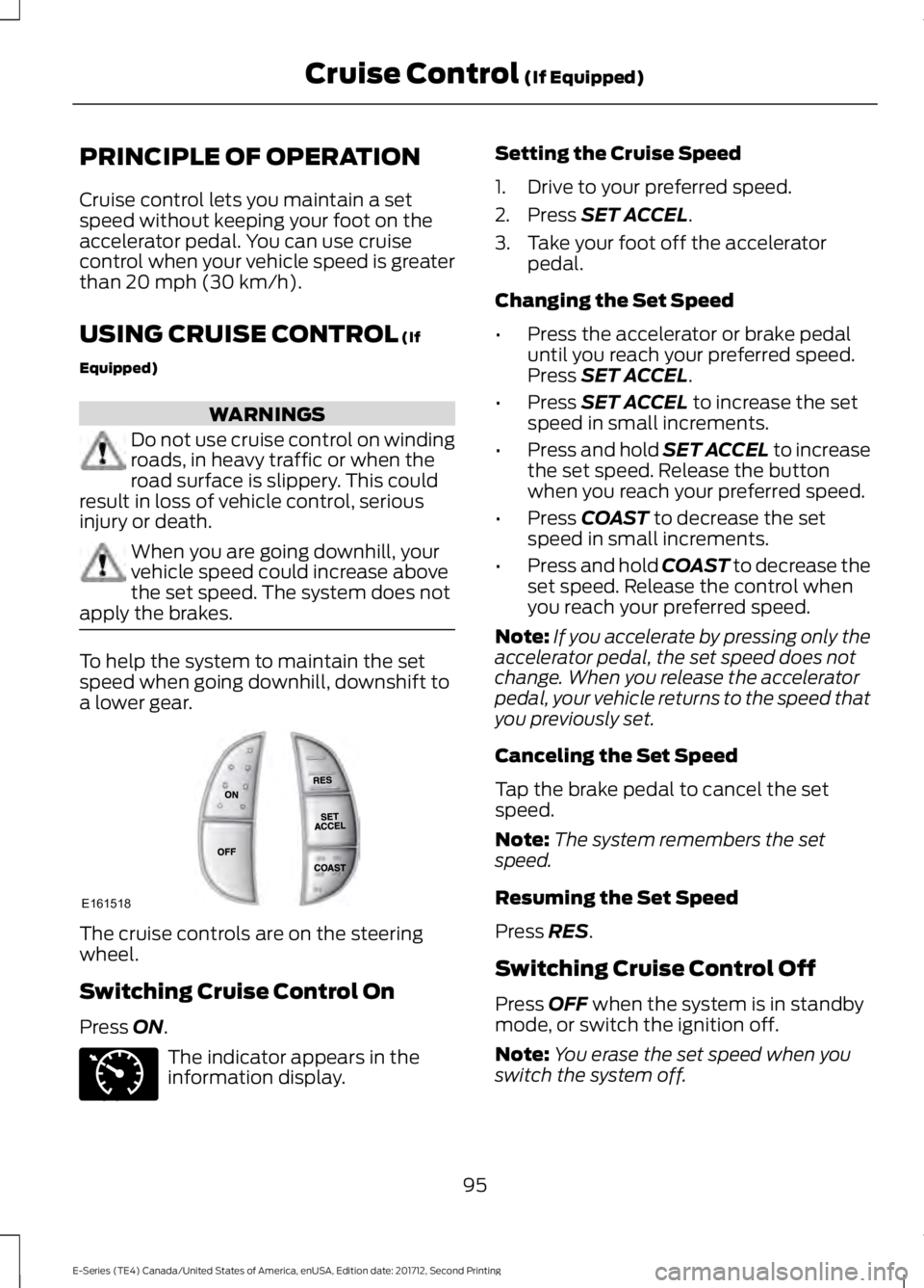
The cruise controls are on the steering
wheel.
Switching Cruise Control On
Press
ON.
The indicator appears in the
information display. Setting the Cruise Speed
1. Drive to your preferred speed.
2. Press
SET ACCEL.
3. Take your foot off the accelerator pedal.
Changing the Set Speed
• Press the accelerator or brake pedal
until you reach your preferred speed.
Press
SET ACCEL.
• Press
SET ACCEL to increase the set
speed in small increments.
• Press and hold SET ACCEL to increase
the set speed. Release the button
when you reach your preferred speed.
• Press
COAST to decrease the set
speed in small increments.
• Press and hold COAST to decrease the
set speed. Release the control when
you reach your preferred speed.
Note: If you accelerate by pressing only the
accelerator pedal, the set speed does not
change. When you release the accelerator
pedal, your vehicle returns to the speed that
you previously set.
Canceling the Set Speed
Tap the brake pedal to cancel the set
speed.
Note: The system remembers the set
speed.
Resuming the Set Speed
Press
RES.
Switching Cruise Control Off
Press
OFF when the system is in standby
mode, or switch the ignition off.
Note: You erase the set speed when you
switch the system off.
95
E-Series (TE4) Canada/United States of America, enUSA, Edition date: 201712, Second Printing Cruise Control
(If Equipped)E161518 E71340
Page 112 of 323

Separate functioning brake systems
are required for safe control of towed
vehicles and trailers weighing more
than 1500 pounds (680 kilograms)
when loaded.
Integrated Trailer Brake Controller (If
Equipped)
WARNING
The Ford trailer brake controller has
been verified to be compatible with
trailers having electric-actuated
drum brakes (one to four axles) and
electric-over-hydraulic brakes. It will not
activate hydraulic surge-style trailer
brakes. It is the responsibility of the
customer to ensure that the trailer brakes
are adjusted appropriately, functioning
normally and all electric connections are
properly made. Failure to do so may result
in loss of vehicle control, crash or serious
injury. When used properly, the trailer brake
controller assists in smooth and effective
trailer braking by powering the trailer
’s
electric or electric-over-hydraulic brakes
with a proportional output based on the
towing vehicle ’s brake pressure.
The controller user interface consists of
the following: A: + and - (Gain adjustment buttons):
Pressing these buttons adjusts the
controller's power output to the trailer
brakes in 0.5 increments. You can increase
the gain setting to 10.0 (maximum trailer
braking) or decrease it to 0 (no trailer
braking). The gain setting displays in the
message center.
The controller shows gain setting, output
bar graph, and trailer connectivity status
in the information display. They appear in
the information display as follows:
• Trailer Brake Controller Gain (without
trailer connected): Shows the current
gain setting during a given ignition cycle
and when adjusting the gain. This also
displays if you use the manual control
lever or make gain adjustments with
no trailer connected.
• Trailer Brake Controller Gain Output:
Displays when you push your vehicle's
brake pedal, or upon use of the manual
control. Bar indicators illuminate in the
information display to indicate the
amount of power going to the trailer
brakes relative to the brake pedal or
manual control input. One bar indicates
the least amount of output; six bars
indicate maximum output.
• Trailer Connected: Displays when the
system senses a correct trailer wiring
connection (a trailer with electric trailer
brakes) during a given ignition cycle.
• Trailer Disconnected: Displays,
accompanied by a single audible time,
when the system senses a trailer
connection and then a disconnection,
either intentional or unintentional,
during a given ignition cycle. It also
displays if a truck or trailer-wiring fault
occurs causing the trailer to appear
disconnected. This message can also
display if you use the manual control
lever without a trailer connected.
109
E-Series (TE4) Canada/United States of America, enUSA, Edition date: 201712, Second Printing TowingE183395
Page 114 of 323

wiring. Consult your trailer dealer for
assistance. This can be a short to ground
(such as a chaffed wire), short to voltage
(such as a pulled pin on trailer emergency
breakaway battery) or the trailer brakes
may be drawing too much current.
Points to Remember
Note:
Do not attempt removal of the trailer
brake controller without consulting the
Workshop Manual. Damage to the unit may
result.
• Adjust gain setting before using the
trailer brake controller for the first time.
• Adjust gain setting, using the procedure
above, whenever road, weather and
trailer or vehicle loading conditions
change from when the gain was initially
set.
• Only use the manual control lever for
proper adjustment of the gain during
trailer setup. Misuse, such as
application during trailer sway, could
cause instability of trailer or tow
vehicle.
• Avoid towing in adverse weather
conditions. The trailer brake controller
does not provide anti-lock control of
the trailer wheels. Trailer wheels can
lock up on slippery surfaces, resulting
in reduced stability of trailer and tow
vehicle.
• The trailer brake controller is equipped
with a feature that reduces output at
vehicle speeds below 11 mph (18 km/h)
so trailer and vehicle braking is not jerky
or harsh. This feature is only available
when applying the brakes using your
vehicle's brake pedal, not the
controller.
• The controller interacts with the brake
control system and powertrain control
system of your vehicle to provide the
best performance on different road
conditions. •
Your vehicle's brake system and the
trailer brake system work
independently of each other. Changing
the gain setting on the controller does
not affect the operation of your
vehicle's brakes whether you attach a
trailer or not.
• When you switch the engine off, the
controller output is disabled and the
display and module shut down. The
controller module and display turn on
when you switch the ignition on.
• The trailer brake controller is only a
factory-installed or dealer-installed
item. Ford is not responsible for
warranty or performance of the
controller due to misuse or customer
installation.
Trailer Lamps WARNING
Never connect any trailer lamp wiring
to the vehicle's tail lamp wiring; this
may damage the electrical system
resulting in fire. Contact your authorized
dealer as soon as possible for assistance
in proper trailer tow wiring installation.
Additional electrical equipment may be
required. Trailer lamps are required on most towed
vehicles. Make sure all running lights, brake
lights, direction indicators and hazard lights
are working.
Before Towing a Trailer
Practice turning, stopping and backing up
to get the feel of your vehicle-trailer
combination before starting on a trip.
When turning, make wider turns so the
trailer wheels clear curbs and other
obstacles.
111
E-Series (TE4) Canada/United States of America, enUSA, Edition date: 201712, Second Printing Towing
Page 116 of 323

Exceeding these limits may allow water to
enter vehicle components:
•
Causing internal damage to the
components.
• Affecting driveability, emissions and
reliability.
Replace the rear axle lubricant anytime
the rear axle has been submerged in water.
Water may have contaminated the rear
axle lubricant, which is not normally
checked or changed unless a leak is
suspected or other axle repair is required.
TOWING THE VEHICLE ON
FOUR WHEELS
Emergency Towing WARNING
If your vehicle has a steering wheel
lock make sure the ignition is in the
accessory or on position when being
towed. You can flat-tow (all wheels on the
ground, regardless of the powertrain or
transmission configuration) your disabled
vehicle (without access to wheel dollies
or vehicle transport trailer) under the
following conditions:
•
Your vehicle is facing forward so you
tow it in a forward direction.
• You shift into Neutral (N). If you cannot
shift into Neutral (N), you may need to
override the transmission. See
Transmission (page 86).
• Maximum speed is 35 mph (56 km/h).
• Maximum distance is
50 mi (80 km). Recreational Towing
Note:
Put your climate control system in
recirculated air mode to prevent exhaust
fumes from entering the vehicle. See
Climate Control
(page 64).
Follow these guidelines if you have a need
for recreational (RV) towing. An example
of recreational towing would be towing
your vehicle behind a motorhome. These
guidelines are to make sure you do not
damage the transmission during towing.
Do not tow your vehicle with any wheels
on the ground, as vehicle or transmission
damage may occur. It is recommended to
tow your vehicle with all four wheels off
the ground, for example when using a
vehicle transport trailer. Otherwise, you
cannot tow your vehicle.
113
E-Series (TE4) Canada/United States of America, enUSA, Edition date: 201712, Second Printing Towing
Page 134 of 323

Protected Components
Fuse Rating
Fuse or Relay
Number
Back-up lamp.
20A 3
28
Air conditioning clutch.
10A 3
29
Brake on/off switch.
10A 3
30
Cluster battery (stripped chassis).
10A 3
31
Blower motor.
50A 2
32
Anti-lock brake system pump.
40A 2
33
Stripped chassis horn.
20A 2
34
Powertrain control module relay.
40A 2
35
Ignition switch (stripped chassis).
20A 2
36
Trailer tow left-hand side stop lamp and
direction indicator lamp relay.
—
37
Trailer tow right-hand side stop lamp and
direction indicator lamp relay.
—
38
Back-up lamp relay.
—
39
Blower motor relay.
—
40
Not used.
—
41
Diagnostic connector (stripped chassis).
15A 3
42
Fuel pump (6.8L).
20A 3
43
Auxiliary switch #3.
10A 3
44
Auxiliary switch #4.
15A 3
45
Powertrain control module keep alive
memory power.
10A 3
46
Canister vent control valve.
Powertrain control module relay coil.
Anti-lock brake system relay coil.
40A 2
47
131
E-Series (TE4) Canada/United States of America, enUSA, Edition date: 201712, Second Printing Fuses
Page 136 of 323

Protected Components
Fuse Rating
Fuse or Relay
Number
Stripped chassis.
30A 2
70
Not used.
—
71
Cigarette lighter/power point.
20A 2
72
Not used.
—
73
Power seat.
30A 2
74
Vehicle power 1.
20A 3
75
Powertrain control module power.
Vehicle power 2.
20A 3
76
Powertrain control module emissions
related components.
Vehicle power 3.
10A 3
77
Powertrain control module general
components.
Vehicle power 4.
15A 3
78
Engine ignition coil relay coil.
Vehicle power 5.
10A 3
79
Transmission.
Cluster run/start (stripped chassis).
10A 3
80
Not used.
—
81
Not used.
—
82
Fuel pump diode.
—
83
Not used.
—
84
Auxiliary switch #1 relay.
—
85
1 Cartridge fuse
2 A1S fuse
3 Mini fuse
133
E-Series (TE4) Canada/United States of America, enUSA, Edition date: 201712, Second Printing Fuses