2018 FIAT 500L bulb
[x] Cancel search: bulbPage 28 of 268

COURTESY LIGHTS
The function can be enabled and its
times set use the "Settings" Menu
of theUconnect™system. When the
doors are unlocked, the side lights
and puddle lights come on for the time
set in the menu.
Once any door is opened, the lights
remain on for a further 180 seconds, or
for a further 10 seconds after the door
is closed.
“FOLLOW ME HOME”
DEVICE
This allows the space in front of the car
to be lit for a set time.
Activation
With the key turned to STOP or
removed, pull the left-hand stalk
towards the steering wheel within 2
minutes from when the engine is turned
off. Each time the stalk is operated,
the lights stay on for an extra 30
seconds up to a maximum of 210
seconds. When this time is up the lights
automatically switch off.Each time the stalk is operated, the
warning light
on the instrument
panel switches on. The display shows a
message and the time set for the
function. The
warning light comes
on when the stalk is first operated
and stays on until the function is
automatically deactivated.
Deactivation
Keep the stalk pulled towards the
steering wheel for more than 2
seconds.
WARNING
20)The daytime running lights are an
alternative to the dipped beam headlights
for driving during the daytime in countries
where it is compulsory to have lights on
during the day; where it is not compulsory,
the use of daytime running lights is
permitted.
21)Daytime running lights cannot replace
dipped beam headlights when driving at
night or through tunnels. The use of
daytime running lights is governed by the
Highway Code of the country in which you
are driving. Comply with legal
requirements.
INTERIOR LIGHTS
FRONT CEILING LIGHT
Switch A fig. 30 is used to switch on/off
the roof light bulbs.
Switch A positions:
central position: lights C and E
switch on/off when the doors are
opened/closed;
pressed to the left (position OFF):
lights C and E are always switched off;
pressed to the right (position):
lights C and D are always switched on.
The lights switch on/off progressively,
controlled by a timer, when the driver
enters and exits the car.
30F0Y0098C
26
KNOWING YOUR CAR
Page 69 of 268

Symbol What it means
DPF CLEANING (particulate trap) in progress (diesel versions with DPF only)
The symbol switches on constantly to indicate that the DPF system needs to eliminate the
trapped pollutants (particulate) through the regeneration process.
The symbol does not switch on during every DPF regeneration, but only when driving
conditions require that the driver is notified. To turn off the symbol, keep the car in motion
until the regeneration process is over. On average, the process lasts 15 minutes. Optimal
conditions for completing the process are achieved by travelling at 60 km/h with engine
speed above 2000 rpm.
When this symbol switches on, it does not indicate a defect of the car and thus it should
not be taken to a workshop.
34)
EXTERIOR LIGHTS FAILURE
The symbol switches on to indicate a failure on the following lights: daytime running lights
(DRLs); parking lights; side lights; direction indicators; rear fog light; reversing light; number
plate lights; stop lights.
The anomaly may be caused by a blown bulb, a blown protection fuse or an interruption of
the electrical connection.
DUSK SENSOR FAILURE
(for versions/markets, where provided)
The symbol switches on in the case of failure of the dusk sensor. Contact a Fiat Dealership
as soon as possible.
RAIN SENSOR FAILURE
(for versions/markets, where provided)
The symbol switches on in the case of failure of the rain sensor. Contact a Fiat Dealership
as soon as possible.
START&STOP SYSTEM FAILURE
The symbol appears to indicate a Start&Stop system failure. The display will show a
dedicated message. Contact a Fiat Dealership as soon as possible.
67
Page 124 of 268

IN AN EMERGENCY
A punctured tyre or a burnt-out bulb?
At times, a problem may interfere
with our journey.
The pages on emergencies can help
you to deal with critical situations
independently and with calm.
In an emergency we recommend that
you call the freephone number found in
the Warranty Booklet.
It is also possible to call the national or
international universal freephone
number to search for the nearest
Dealership.HAZARD WARNING LIGHTS...........123
REPLACING A WHEEL ...................123
“FIX&GO AUTOMATIC” KIT .............127
REPLACING A BULB ......................130
REPLACING FUSES........................137
JUMP STARTING ............................143
FUEL CUT-OFF SYSTEM ................145
TOWING THE VEHICLE ..................145
122
IN AN EMERGENCY
Page 132 of 268

WARNING
63)The sealant is effective with external
temperatures of between -40°C and
+55°C. The sealant has an expiry date. It is
possible to repair tyres which have been
damaged on tread up to a diameter of
6 mm. Show the cartridge and the label to
the personnel charged with handling the
tyre treated with the tyre repair kit.
WARNING
2)Dispose of the bottle and the sealant
liquid properly. Have the sealing fluid and
the bottle disposed of in compliance
with national and local regulations.
REPLACING A BULB
132) 133)64) 65)
GENERAL
INSTRUCTIONS
Before replacing a bulb check the
contacts for oxidation.
Burnt bulbs must be replaced by
others of the same type and power.
After replacing a headlight bulb,
always check that alignment of the light
beam is correct.
when a light is not working, check
that the corresponding fuse is intact
before replacing a bulb. For the location
of fuses, refer to the paragraph
"Replacing fuses" in this chapter.IMPORTANT When the weather is cold
or damp or after heavy rain or washing,
the surface of headlights or rear lights
may steam up and/or form drops of
condensation on the inside. This is
a natural phenomenon due to the
difference in temperature and humidity
between the inside and the outside
of the glass which does not indicate a
fault and does not compromise the
normal operation of lighting devices.
The mist disappears quickly when the
lights are turned on, starting from
the centre of the diffuser, extending
progressively towards the edges.
130
IN AN EMERGENCY
Page 133 of 268

TYPES OF BULBS
UseType Power
Dipped/main beam headlights H7 55W
Daytime running lights (DRL) LED + bulb W21W 21W
Front side lights LED –
Rear side lights/Brake lights P21/5W 21W/5W
Front direction indicators PY21W 21W
Side direction indicators WY5W 5W
Rear direction indicators P21W 21W
Third brake light LED –
Fog lights H11 55W
Reversing light W16W 16W
Rear fog light W16W 16W
Number plate C5W 5W
Front ceiling light C5W 5W
Front roof lights (sun visors) C5W 5W
Luggage compartment light W5W 5W
Glove compartment light C5W 5W
Rear ceiling lights C5W 5W
131
Page 134 of 268

FRONT UPPER LIGHT
CLUSTER
This contains the bulbs for the direction
indicators and dipped headlights.
The bulbs are arranged as follows fig.
136:
A: direction indicators
B: dipped beam headlights
DIRECTION INDICATORS
To replace the bulb, proceed as follows:
remove cover A fig. 136;
turn bulb holder B fig. 137
anticlockwise, extract bulb C and
replace it;
refit the new bulb on the bulb holder,
making sure it is correctly locked;
refit the bulb holder in its housing
and turn it clockwise, until the locking
click is heard;
then refit the cover A fig. 136.DIPPED BEAM
HEADLIGHTS
To replace the bulb, proceed as follows:
remove cover B fig. 136;
remove the connector and bulb
holder C fig. 138 unit, releasing it
outwards;
remove bulb D from connector E
and replace it;
refit the new bulb on the connector,
making sure it is correctly locked;
refit the connector and bulb holder C
unit in its housing;
then refit the cover B fig. 136.
FRONT LOWER LIGHT
CLUSTER
This contains the bulbs for the main
beams and side lights/daytime running
lights (DRL).
The bulbs are arranged as follows fig.
139:
C: main beam headlights
D: side lights/daytime running lights
(DRL)
MAIN BEAM HEADLIGHTS
To replace the bulb, proceed as
follows:
steer the wheel completely inwards;
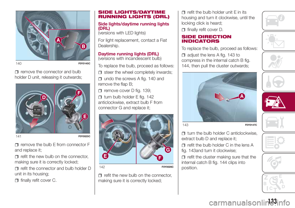
undo the screws A fig. 140 and
remove the flap B;
remove cover C fig. 139;
136F0Y0021C
137F0Y0022C
138F0Y0023C
139F0Y0499C
132
IN AN EMERGENCY
Page 135 of 268

remove the connector and bulb
holder D unit, releasing it outwards;
remove the bulb E from connector F
and replace it;
refit the new bulb on the connector,
making sure it is correctly locked;
refit the connector and bulb holder D
unit in its housing;
finally refit cover C.SIDE LIGHTS/DAYTIME
RUNNING LIGHTS (DRL)
Side lights/daytime running lights
(DRL)
(versions with LED lights)
For light replacement, contact a Fiat
Dealership.
Daytime running lights (DRL)
(versions with incandescent bulb)
To replace the bulb, proceed as follows:
steer the wheel completely inwards;
undo the screws A fig. 140 and
remove the flap B;
remove cover D fig. 139;
turn bulb holder E fig. 142
anticlockwise, extract bulb F from
connector G and replace it;
refit the new bulb on the connector,
making sure it is correctly locked;
refit the bulb holder unit E in its
housing and turn it clockwise, until the
locking click is heard;
finally refit cover D.
SIDE DIRECTION
INDICATORS
To replace the bulb, proceed as follows:
adjust the lens A fig. 143 to
compress in the internal catch B fig.
144, then pull the cluster outwards;
turn the bulb holder C anticlockwise,
extract bulb D and replace it;
refit the bulb holder C in the lens A
fig. 143and turn it clockwise;
refit the cluster making sure that the
internal catch B fig. 144 clips into
position.
140F0Y0145C
141F0Y0025C
142F0Y0026C
143F0Y0147C
133
Page 136 of 268

FOG LIGHTS
(for versions/markets, where provided)
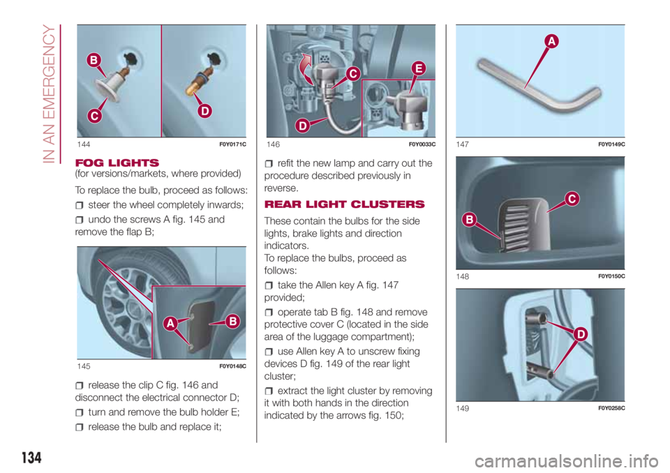
To replace the bulb, proceed as follows:
steer the wheel completely inwards;
undo the screws A fig. 145 and
remove the flap B;
release the clip C fig. 146 and
disconnect the electrical connector D;
turn and remove the bulb holder E;
release the bulb and replace it;
refit the new lamp and carry out the
procedure described previously in
reverse.
REAR LIGHT CLUSTERS
These contain the bulbs for the side
lights, brake lights and direction
indicators.
To replace the bulbs, proceed as
follows:
take the Allen key A fig. 147
provided;
operate tab B fig. 148 and remove
protective cover C (located in the side
area of the luggage compartment);
use Allen key A to unscrew fixing
devices D fig. 149 of the rear light
cluster;
extract the light cluster by removing
it with both hands in the direction
indicated by the arrows fig. 150;
144F0Y0171C
145F0Y0148C
146F0Y0033C147F0Y0149C
148F0Y0150C
149F0Y0258C
134
IN AN EMERGENCY