Page 244 of 553
FUEL SAVER TECHNOLOGY 5.7L AND 6.4L ONLY —
IF EQUIPPED
This feature offers improved fuel economy by shutting off
four of the engine’s eight cylinders during light load and
cruise conditions. The system is automatic with no driver
inputs or additional driving skills required.
NOTE:This system may take some time to return to full
functionality after a battery disconnect.
POWER STEERING
The electric power steering system will give you good
vehicle response and increased ease of maneuverability in
tight spaces. The system will vary its assist to provide light
efforts while parking and good feel while driving. If the
electric steering system experiences a fault that prevents it
from providing assist, you will still have the ability to steer
the vehicle manually.
WARNING!
Continued operation with reduced assist could pose a
safety risk to yourself and others. Service should be
obtained as soon as possible. Alternate electric power steering efforts can be selected
through the Uconnect System. Refer to ”Customer Pro-
grammable Features” within “Uconnect Settings” in “Mul-
timedia” for further information.
If the Electric Power Steering warning icon is
displayed and the “SERVICE POWER STEER-
ING” or the “POWER STEERING ASSIST OFF –
SERVICE SYSTEM” message is displayed within
the instrument cluster display, this indicates the vehicle
needs to be taken to the dealer for service. Refer to
“Warning Lights And Messages” in “Getting To Know
Your Instrument Panel” for further information.
NOTE:
• Even if the power steering assistance is no longer
operational, it is still possible to steer the vehicle. Under
these conditions there will be a substantial increase in
steering effort, especially at low speeds and during
parking maneuvers.
• If the condition persists, see your authorized dealer for
service.
242 STARTING AND OPERATING
Page 245 of 553
If the Steering icon is displayed and the “POWER STEER-
ING SYSTEM OVER TEMP” message is displayed on the
instrument cluster screen, they indicate that extreme steer-
ing maneuvers may have occurred which caused an over
temperature condition in the power steering system. Once
driving conditions are safe, pull over and let the vehicle
idle for a few moments until the icon and message turn off.
SPEED CONTROL — IF EQUIPPED
When engaged, the Speed Control takes over accelerator
operations at speeds greater than 25 mph (40 km/h).
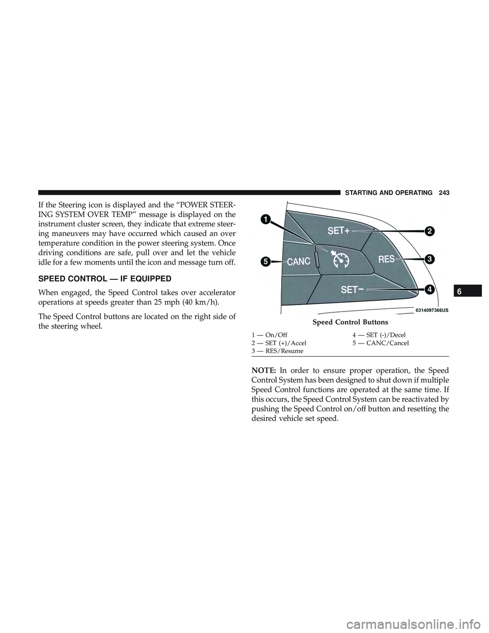
The Speed Control buttons are located on the right side of
the steering wheel.NOTE:In order to ensure proper operation, the Speed
Control System has been designed to shut down if multiple
Speed Control functions are operated at the same time. If
this occurs, the Speed Control System can be reactivated by
pushing the Speed Control on/off button and resetting the
desired vehicle set speed.
Speed Control Buttons
1 — On/Off 4 — SET (-)/Decel
2 — SET (+)/Accel 5 — CANC/Cancel
3 — RES/Resume
6
STARTING AND OPERATING 243
Page 289 of 553
Trailer Sway Control
The trailer sway control can be a mechanical telescoping
link that can be installed between the hitch receiver and the
trailer tongue that typically provides adjustable friction
associated with the telescoping motion to dampen any
unwanted trailer swaying motions while traveling.
If equipped, the electronic Trailer Sway Control (TSC)
recognizes a swaying trailer and automatically applies
individual wheel brakes and/or reduces engine power to
attempt to eliminate the trailer sway.
Weight-Carrying Hitch
A weight-carrying hitch supports the trailer tongue weight,
just as if it were luggage located at a hitch ball or some
other connecting point of the vehicle. These kinds of
hitches are the most popular on the market today and they
are commonly used to tow small and medium sized
trailers.
Weight-Distributing Hitch
A weight-distributing system works by applying leverage
through spring (load) bars. They are typically used for
heavier loads to distribute trailer tongue weight to the towvehicle’s front axle and the trailer axle(s). When used in
accordance with the manufacturer’s directions, it provides
for a more level ride, offering more consistent steering and
brake control thereby enhancing towing safety. The addi-
tion of a friction/hydraulic sway control also dampens
sway caused by traffic and crosswinds and contributes
positively to tow vehicle and trailer stability. Trailer sway
control and a weight distributing (load equalizing) hitch
are recommended for heavier Tongue Weights (TW) and
may be required depending on vehicle and trailer
configuration/loading to comply with Gross Axle Weight
Rating (GAWR) requirements.
WARNING!
•
An improperly adjusted Weight Distributing Hitch
system may reduce handling, stability, braking per-
formance, and could result in a collision.
• Weight Distributing Systems may not be compatible
with Surge Brake Couplers. Consult with your hitch
and trailer manufacturer or a reputable Recreational
Vehicle dealer for additional information.
6
STARTING AND OPERATING 287
Page 307 of 553
•The Device Screen will display the following message
“Vehicle device requires service. Please contact your
dealer.”
• An In-Vehicle Audio message will state “Vehicle device
requires service. Please contact your dealer.”
WARNING!
•Ignoring the Rearview Mirror light could mean you
will not have SOS Call services. If the Rearview
Mirror light is illuminated, have an authorized
dealer service the SOS Call system immediately.
• The Occupant Restraint Control module turns on the
air bag Warning Light on the instrument panel if a
malfunction in any part of the system is detected. If
the Air Bag Warning Light is illuminated, have an
authorized dealer service the Occupant Restraint
Control system immediately.
Even if the SOS Call system is fully functional, factors
beyond FCA US LLC’s control may prevent or stop the SOS
Call system operation. These include, but are not limited
to, the following factors:
• Delayed accessories mode is active.
• The ignition is in the OFF position. •
The vehicle’s electrical systems are not intact.
• The SOS Call system software and/or hardware are
damaged during a crash.
• The vehicle battery loses power or becomes discon-
nected during a vehicle crash.
• LTE (voice/data) or 4G (data) network and/or Global
Positioning Satellite signals are unavailable or ob-
structed.
• Equipment malfunction at the SOS operator facility.
• Operator error by the SOS operator.
• LTE (voice/data) or 4G (data) network congestion.
• Weather.
• Buildings, structures, geographic terrain, or tunnels.
WARNING!
ALWAYS obey traffic laws and pay attention to the
road. ALWAYS drive safely with your hands on the
steering wheel. You have full responsibility and as-
sume all risks related to the use of the Uconnect and
SiriusXM Guardian features and applications in this
(Continued)
7
IN CASE OF EMERGENCY 305
Page 313 of 553
5. Disconnect the bulb from the wiring connector andinstall the replacement bulb.
6. Install the bulb and connector assembly straight into the lamp until it locks in place.
7. Install the turn signal bulb cap in the headlamp housing and rotate clockwise to lock in place.
Backup Lamps
The Backup Lamps use LED sources that are not service-
able separately. The Applique must be replaced as an
assembly; see your authorized dealer.
License Lamp
The License Lamp uses an LED source that is not service-
able separately. The License Lamp must be replaced as an
assembly; see your authorized dealer.
Center High Mounted Stop Lamp (CHMSL)
The CHMSL Lamp uses LED sources that are not service-
able separately. The CHMSL Lamp must be replaced as an
assembly; see your authorized dealer.
FUSES
WARNING!
•When replacing a blown fuse, always use an appro-
priate replacement fuse with the same amp rating as
the original fuse. Never replace a fuse with another
fuse of higher amp rating. Never replace a blown
fuse with metal wires or any other material. Do not
place a fuse inside a circuit breaker cavity or vice
versa. Failure to use proper fuses may result in
serious personal injury, fire and/or property damage.
• Before replacing a fuse, make sure that the ignition is
off and that all the other services are switched off
and/or disengaged.
• If the replaced fuse blows again, contact an autho-
rized dealer.
• If a general protection fuse for safety systems (air
bag system, braking system), power unit systems
(engine system, transmission system) or steering
system blows, contact an authorized dealer.
7
IN CASE OF EMERGENCY 311
Page 315 of 553
CAUTION!
•When installing the power distribution center cover,
it is important to ensure the cover is properly posi-
tioned and fully latched. Failure to do so may allow
water to get into the power distribution center and
possibly result in an electrical system failure.
• When replacing a blown fuse, it is important to use
only a fuse having the correct amperage rating. The
use of a fuse with a rating other than indicated may
result in a dangerous electrical system overload. If a
properly rated fuse continues to blow, it indicates a
problem in the circuit that must be corrected.
Cavity Cartridge Fuse Mini-Fuse Description
1 –– Fuse – Spare
2 40 Amp Green –Radiator Fan #1 – (Non 6.2L Supercharged)
3 50 Amp Red –Electric Power Steering #1 – If Equipped
4 30 Amp Pink – Starter
5 40 Amp Green –Anti Lock Brake
Front Power Distribution Center
7
IN CASE OF EMERGENCY 313
Page 316 of 553
CavityCartridge Fuse Mini-Fuse Description
6 30 Amp Pink –Anti Lock Brake
7 20 Amp Blue –Police Ignition Run / ACC #1
8 50 Amp Red / 20
Amp Blue –
Radiator Fan (6.2L Supercharged) / Police
Ignition Run / ACC # 2
9 –20 Amp Yellow All-Wheel Drive Module – If Equipped
10 –10 Amp Red Intrusion MOD (300) – If Equipped / Under
Hood Lamp – Police
11 –20 Amp Yellow Horns
12 –10 Amp Red Air Conditioning Clutch
13 –– Fuse – Spare
14 –– Fuse – Spare
15 –20 Amp Yellow Left HID – If Equipped
16 –20 Amp Yellow Right HID – If Equipped
18 50 Amp Red –Radiator Fan – (Non 6.2L Supercharged)
19 50 Amp Red –Electric Power Steering #2 – If Equipped
20 30 Amp Pink – Wiper Motor
21 30 Amp Pink
20 Amp Blue – Po- lice –
Headlamp Washers – If Equipped
Police Bat Feed #2
314 IN CASE OF EMERGENCY
Page 317 of 553
CavityCartridge Fuse Mini-Fuse Description
22 40 Amp Green / 20
Amp Blue – Police –
Engine Cooling Pump (6.2L Supercharged) /
Police Bat Feed # 3
23 20 Amp Blue –Police Bat Feed # 1
24 50 Amp Red / 20
Amp Blue –
Radiator Fan (6.2L Supercharged) / Police
Ignition Run/ACC Feed # 3
28 –– Fuse – Spare
29 –15 Amp Blue Transmission Control Module (Challenger/
Charger Police) / Electronic Shift Module(Challenger)
30 –– Fuse – Spare
31 –25 Amp Clear Engine Module
32 –– Fuse – Spare
33 –– Fuse – Spare
34 –25 Amp Clear Powertrain #1
35 –20 Amp Yellow Powertrain #2
36 –10 Amp Red Anti-Lock Brake Module
37 –10 Amp Red Engine Controller / Rad Fan Relays
(Charger/300) / Electric Power Steering Mod- ule (Charger/300) / 5-Speed TCM
38 –10 Amp Red Airbag Module
7
IN CASE OF EMERGENCY 315