2018 DODGE CHARGER mirror
[x] Cancel search: mirrorPage 65 of 553
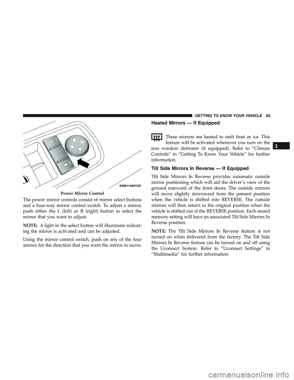
The power mirror controls consist of mirror select buttons
and a four-way mirror control switch. To adjust a mirror,
push either the L (left) or R (right) button to select the
mirror that you want to adjust.
NOTE:A light in the select button will illuminate indicat-
ing the mirror is activated and can be adjusted.
Using the mirror control switch, push on any of the four
arrows for the direction that you want the mirror to move.
Heated Mirrors — If Equipped
These mirrors are heated to melt frost or ice. This
feature will be activated whenever you turn on the
rear window defroster (if equipped). Refer to “Climate
Controls” in “Getting To Know Your Vehicle” for further
information.
Tilt Side Mirrors In Reverse — If Equipped
Tilt Side Mirrors In Reverse provides automatic outside
mirror positioning which will aid the driver ’s view of the
ground rearward of the front doors. The outside mirrors
will move slightly downward from the present position
when the vehicle is shifted into REVERSE. The outside
mirrors will then return to the original position when the
vehicle is shifted out of the REVERSE position. Each stored
memory setting will have an associated Tilt Side Mirrors In
Reverse position.
NOTE: The Tilt Side Mirrors In Reverse feature is not
turned on when delivered from the factory. The Tilt Side
Mirrors In Reverse feature can be turned on and off using
the Uconnect System. Refer to “Uconnect Settings” in
“Multimedia” for further information.
Power Mirror Control
3
GETTING TO KNOW YOUR VEHICLE 63
Page 66 of 553
Illuminated Vanity Mirrors — If Equipped
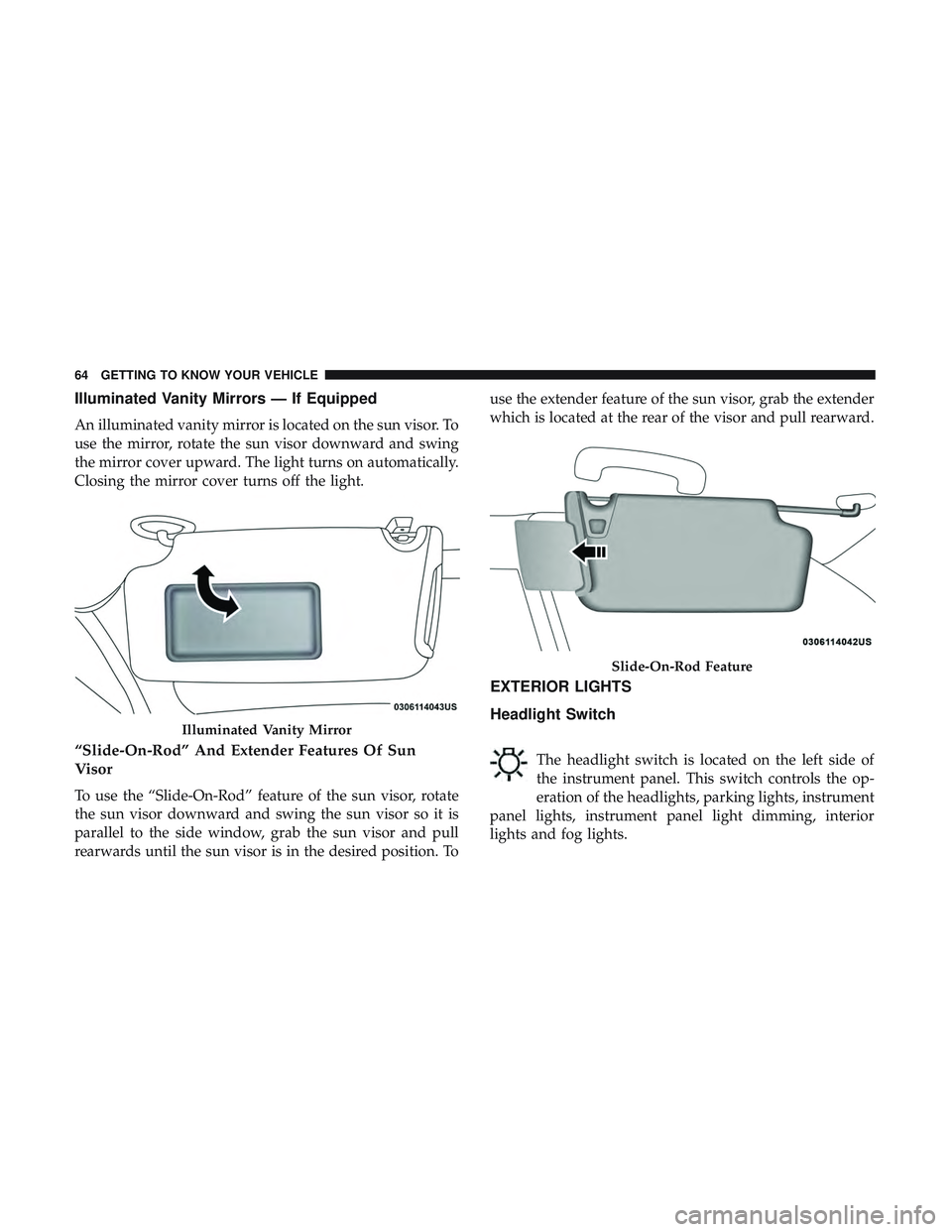
An illuminated vanity mirror is located on the sun visor. To
use the mirror, rotate the sun visor downward and swing
the mirror cover upward. The light turns on automatically.
Closing the mirror cover turns off the light.
“Slide-On-Rod” And Extender Features Of Sun
Visor
To use the “Slide-On-Rod” feature of the sun visor, rotate
the sun visor downward and swing the sun visor so it is
parallel to the side window, grab the sun visor and pull
rearwards until the sun visor is in the desired position. Touse the extender feature of the sun visor, grab the extender
which is located at the rear of the visor and pull rearward.
EXTERIOR LIGHTS
Headlight Switch
The headlight switch is located on the left side of
the instrument panel. This switch controls the op-
eration of the headlights, parking lights, instrument
panel lights, instrument panel light dimming, interior
lights and fog lights.
Illuminated Vanity Mirror
Slide-On-Rod Feature
64 GETTING TO KNOW YOUR VEHICLE
Page 68 of 553

High/Low Beam Switch
Push the multifunction lever away from you to switch the
headlights to high beam. Pull the multifunction lever
toward you to switch the headlights back to low beam.
Automatic High Beam — If Equipped
The Automatic High Beam Headlamp Control system
provides increased forward lighting at night by automat-
ing high beam control through the use of a digital camera
mounted on the inside rearview mirror. This camera de-
tects vehicle specific light and automatically switches from
high beams to low beams until the approaching vehicle is
out of view.
NOTE:
•The Automatic High Beam Headlamp Control can be
turned on or off by selecting “ON” under “Auto High
Beam” within your Uconnect settings, as well as turning
the headlight switch to the AUTO position. Refer to
“Uconnect Settings” in “Multimedia” for further infor-
mation. •
Broken, muddy, or obstructed headlights and taillights
of vehicles in the field of view will cause headlights to
remain on longer (closer to the vehicle). Also, dirt, film,
and other obstructions on the windshield or camera lens
will cause the system to function improperly.
If the windshield or Automatic High Beam Headlamp
Control mirror is replaced, the mirror must be re-aimed to
ensure proper performance. See your local authorized
dealer.
To Activate
1. Turn the headlight switch to the AUTO headlight posi- tion.
2. Push the multifunction lever away from you (toward front of vehicle) to engage the high beam mode.
NOTE: This system will not activate until the vehicle is at
or above 15 mph (24 km/h).
66 GETTING TO KNOW YOUR VEHICLE
Page 81 of 553
IconDescription
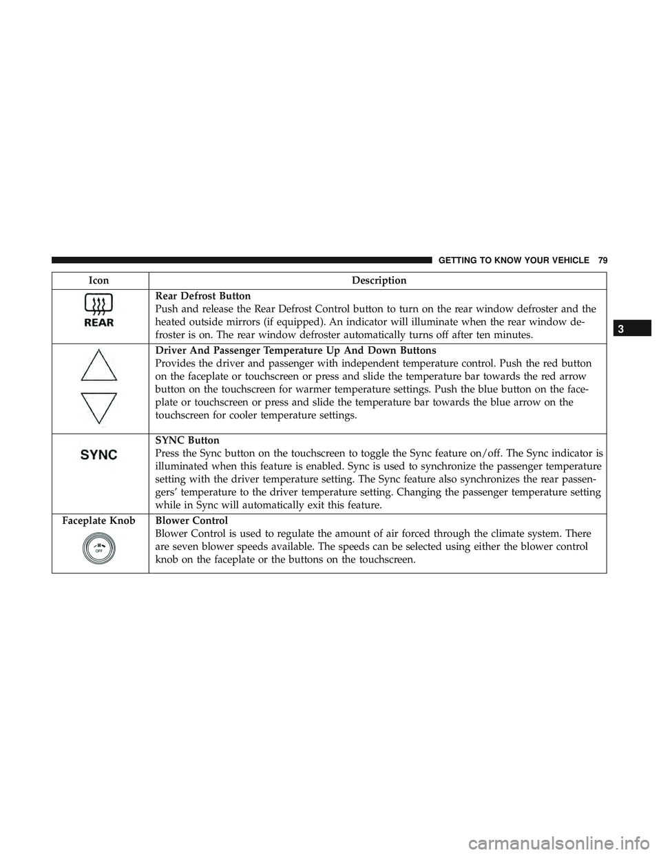
Rear Defrost Button
Push and release the Rear Defrost Control button to turn on the rear window defroster and the
heated outside mirrors (if equipped). An indicator will illuminate when the rear window de-
froster is on. The rear window defroster automatically turns off after ten minutes.
Driver And Passenger Temperature Up And Down Buttons
Provides the driver and passenger with independent temperature control. Push the red button
on the faceplate or touchscreen or press and slide the temperature bar towards the red arrow
button on the touchscreen for warmer temperature settings. Push the blue button on the face-
plate or touchscreen or press and slide the temperature bar towards the blue arrow on the
touchscreen for cooler temperature settings.
SYNC Button
Press the Sync button on the touchscreen to toggle the Sync feature on/off. The Sync indicator is
illuminated when this feature is enabled. Sync is used to synchronize the passenger temperature
setting with the driver temperature setting. The Sync feature also synchronizes the rear passen-
gers’ temperature to the driver temperature setting. Changing the passenger temperature setting
while in Sync will automatically exit this feature.
Faceplate Knob
Blower Control
Blower Control is used to regulate the amount of air forced through the climate system. There
are seven blower speeds available. The speeds can be selected using either the blower control
knob on the faceplate or the buttons on the touchscreen.
3
GETTING TO KNOW YOUR VEHICLE 79
Page 87 of 553
IconDescription
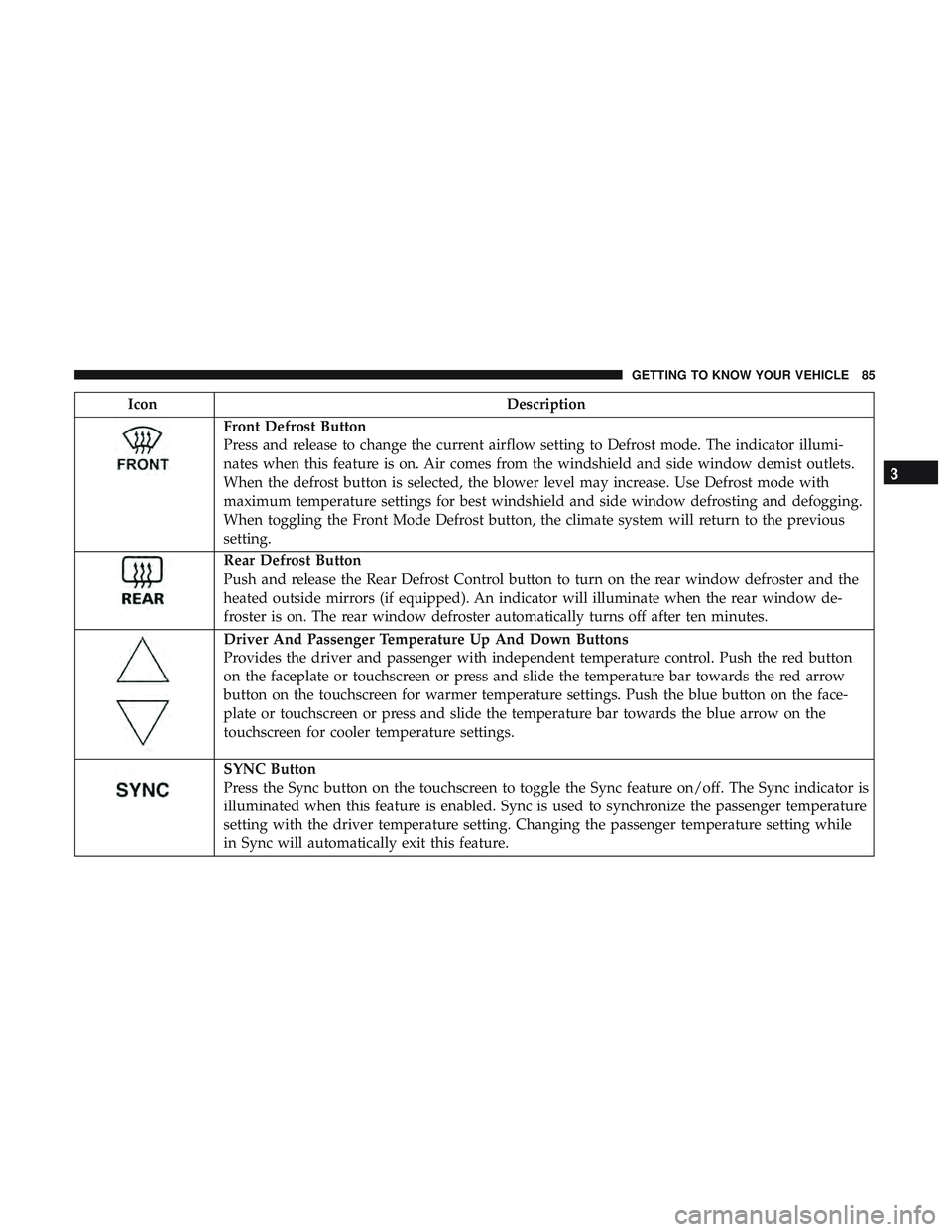
Front Defrost Button
Press and release to change the current airflow setting to Defrost mode. The indicator illumi-
nates when this feature is on. Air comes from the windshield and side window demist outlets.
When the defrost button is selected, the blower level may increase. Use Defrost mode with
maximum temperature settings for best windshield and side window defrosting and defogging.
When toggling the Front Mode Defrost button, the climate system will return to the previous
setting.
Rear Defrost Button
Push and release the Rear Defrost Control button to turn on the rear window defroster and the
heated outside mirrors (if equipped). An indicator will illuminate when the rear window de-
froster is on. The rear window defroster automatically turns off after ten minutes.
Driver And Passenger Temperature Up And Down Buttons
Provides the driver and passenger with independent temperature control. Push the red button
on the faceplate or touchscreen or press and slide the temperature bar towards the red arrow
button on the touchscreen for warmer temperature settings. Push the blue button on the face-
plate or touchscreen or press and slide the temperature bar towards the blue arrow on the
touchscreen for cooler temperature settings.
SYNC Button
Press the Sync button on the touchscreen to toggle the Sync feature on/off. The Sync indicator is
illuminated when this feature is enabled. Sync is used to synchronize the passenger temperature
setting with the driver temperature setting. Changing the passenger temperature setting while
in Sync will automatically exit this feature.
3
GETTING TO KNOW YOUR VEHICLE 85
Page 132 of 553
The electrical loads that may be switched off (if equipped),
and vehicle functions which can be affected by load
reduction:
•Heated Seat/Vented Seats/Heated Wheel
• Heated/Cooled Cup Holders — If Equipped
• Rear Defroster And Heated Mirrors
• HVAC System
• 115V AC Power Inverter System
• Audio and Telematics System
Loss of the battery charge may indicate one or more of the
following conditions:
• The charging system cannot deliver enough electrical
power to the vehicle system because the electrical loads
are larger than the capability of charging system. The
charging system is still functioning properly.
• Turning on all possible vehicle electrical loads (e.g.
HVAC to max settings, exterior and interior lights,
overloaded power outlets +12V, 115V AC, USB ports)
during certain driving conditions (city driving, towing,
frequent stopping). •
Installing options like additional lights, upfitter electri-
cal accessories, audio systems, alarms and similar de-
vices.
• Unusual driving cycles (short trips separated by long
parking periods).
• The vehicle was parked for an extended period of time
(weeks, months).
• The battery was recently replaced and was not charged
completely.
• The battery was discharged by an electrical load left on
when the vehicle was parked.
• The battery was used for an extended period with the
engine not running to supply radio, lights, chargers,
+12V portable appliances like vacuum cleaners, game
consoles and similar devices.
130 GETTING TO KNOW YOUR INSTRUMENT PANEL
Page 158 of 553
AUXILIARY DRIVING SYSTEMS
Blind Spot Monitoring (BSM) — If Equipped
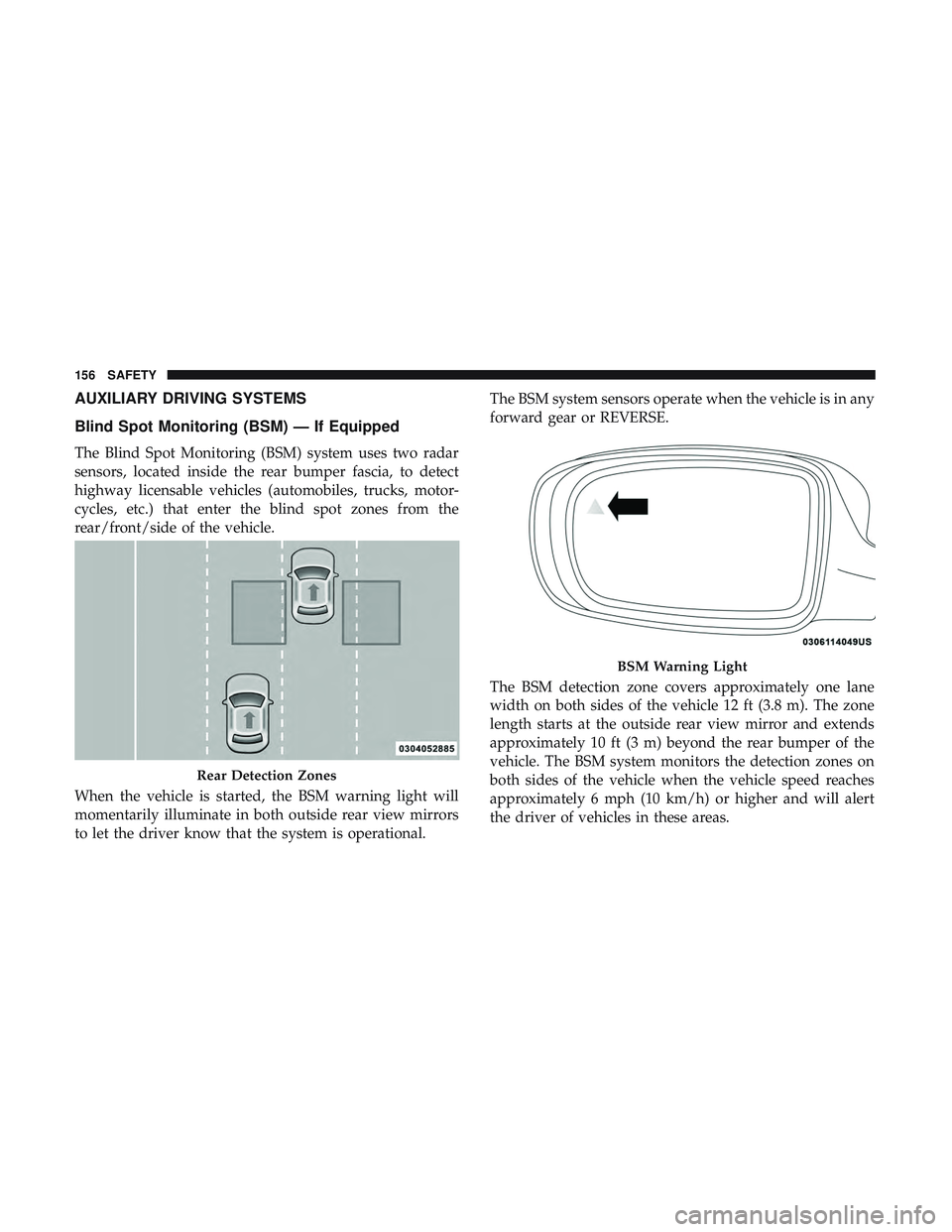
The Blind Spot Monitoring (BSM) system uses two radar
sensors, located inside the rear bumper fascia, to detect
highway licensable vehicles (automobiles, trucks, motor-
cycles, etc.) that enter the blind spot zones from the
rear/front/side of the vehicle.
When the vehicle is started, the BSM warning light will
momentarily illuminate in both outside rear view mirrors
to let the driver know that the system is operational.The BSM system sensors operate when the vehicle is in any
forward gear or REVERSE.
The BSM detection zone covers approximately one lane
width on both sides of the vehicle 12 ft (3.8 m). The zone
length starts at the outside rear view mirror and extends
approximately 10 ft (3 m) beyond the rear bumper of the
vehicle. The BSM system monitors the detection zones on
both sides of the vehicle when the vehicle speed reaches
approximately 6 mph (10 km/h) or higher and will alert
the driver of vehicles in these areas.
Rear Detection Zones
BSM Warning Light
156 SAFETY
Page 159 of 553

NOTE:
•The BSM system does NOT alert the driver about
rapidly approaching vehicles that are outside the detec-
tion zones.
• The BSM system detection zone DOES NOT change if
your vehicle is towing a trailer. Therefore, visually verify
the adjacent lane is clear for both your vehicle and trailer
before making a lane change. If the trailer or other object
(i.e., bicycle, sports equipment) extends beyond the side
of your vehicle, this may result in the BSM warning light
remaining illuminated the entire time the vehicle is in a
forward gear.
• The Blind Spot Monitoring (BSM) system may experi-
ence drop outs (blinking on and off) of the side mirror
Warning Indicator lamps when a motorcycle or any
small object remains at the side of the vehicle for
extended periods of time (more than a couple of sec-
onds).
The area on the rear fascia where the radar sensors are
located must remain free of snow, ice, and dirt/road
contamination so that the BSM system can function prop-
erly. Do not block the area of the rear fascia where the radar
sensors are located with foreign objects (bumper stickers,
bicycle racks, etc.). The BSM system notifies the driver of objects in the
detection zones by illuminating the BSM warning light
located in the outside mirrors in addition to sounding an
audible (chime) alert and reducing the radio volume. Refer
to “Modes Of Operation” for further information.
The BSM system monitors the detection zone from three
different entry points (side, rear, front) while driving to see
if an alert is necessary. The BSM system will issue an alert
during these types of zone entries.
Sensor Location
5
SAFETY 157