Page 317 of 553
CavityCartridge Fuse Mini-Fuse Description
22 40 Amp Green / 20
Amp Blue – Police –
Engine Cooling Pump (6.2L Supercharged) /
Police Bat Feed # 3
23 20 Amp Blue –Police Bat Feed # 1
24 50 Amp Red / 20
Amp Blue –
Radiator Fan (6.2L Supercharged) / Police
Ignition Run/ACC Feed # 3
28 –– Fuse – Spare
29 –15 Amp Blue Transmission Control Module (Challenger/
Charger Police) / Electronic Shift Module(Challenger)
30 –– Fuse – Spare
31 –25 Amp Clear Engine Module
32 –– Fuse – Spare
33 –– Fuse – Spare
34 –25 Amp Clear Powertrain #1
35 –20 Amp Yellow Powertrain #2
36 –10 Amp Red Anti-Lock Brake Module
37 –10 Amp Red Engine Controller / Rad Fan Relays
(Charger/300) / Electric Power Steering Mod- ule (Charger/300) / 5-Speed TCM
38 –10 Amp Red Airbag Module
7
IN CASE OF EMERGENCY 315
Page 325 of 553

CavityCartridge Fuse Mini-FuseDescription
67 –10 Amp Red Rain and Light Sensor /
Sunroof / Inside RR View
Mirror / Police Run Acc
Relay
68 –10 Amp Red Dual USB Power Outlet –
R/A Sense (Charger/300)
Rear Sunshade (Charger/
300) RR USB Timer
69 ––Fuse – Spare
70 ––Fuse – Spare
JACKING AND TIRE CHANGING
WARNING!
•Do not attempt to change a tire on the side of the
vehicle close to moving traffic. Pull far enough off
the road to avoid the danger of being hit when
operating the jack or changing the wheel.
• Being under a jacked-up vehicle is dangerous. The
vehicle could slip off the jack and fall on you. You
could be crushed. Never put any part of your body
(Continued)
WARNING! (Continued)
under a vehicle that is on a jack. If you need to get
under a raised vehicle, take it to a service center
where it can be raised on a lift.
• Never start or run the engine while the vehicle is on
a jack.
• The jack is designed to be used as a tool for changing
tires only. The jack should not be used to lift the
vehicle for service purposes. The vehicle should be
jacked on a firm level surface only. Avoid ice or
slippery areas.
7
IN CASE OF EMERGENCY 323
Page 328 of 553

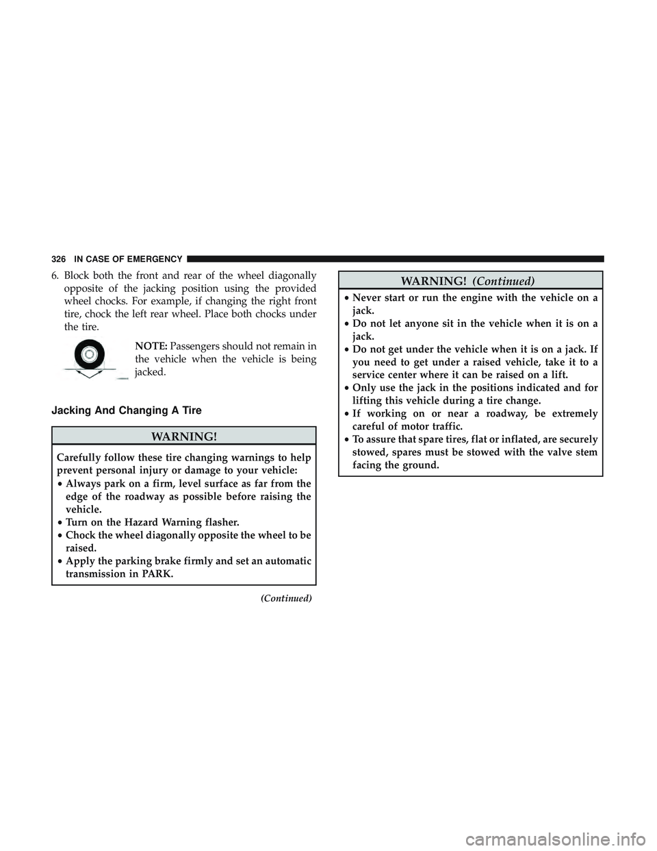
6. Block both the front and rear of the wheel diagonallyopposite of the jacking position using the provided
wheel chocks. For example, if changing the right front
tire, chock the left rear wheel. Place both chocks under
the tire.
NOTE:Passengers should not remain in
the vehicle when the vehicle is being
jacked.
Jacking And Changing A Tire
WARNING!
Carefully follow these tire changing warnings to help
prevent personal injury or damage to your vehicle:
• Always park on a firm, level surface as far from the
edge of the roadway as possible before raising the
vehicle.
• Turn on the Hazard Warning flasher.
• Chock the wheel diagonally opposite the wheel to be
raised.
• Apply the parking brake firmly and set an automatic
transmission in PARK.
(Continued)
WARNING! (Continued)
•Never start or run the engine with the vehicle on a
jack.
• Do not let anyone sit in the vehicle when it is on a
jack.
• Do not get under the vehicle when it is on a jack. If
you need to get under a raised vehicle, take it to a
service center where it can be raised on a lift.
• Only use the jack in the positions indicated and for
lifting this vehicle during a tire change.
• If working on or near a roadway, be extremely
careful of motor traffic.
• To assure that spare tires, flat or inflated, are securely
stowed, spares must be stowed with the valve stem
facing the ground.
326 IN CASE OF EMERGENCY
Page 337 of 553

5. Uncoil the Power Plug (8) and insert the plug into thevehicle’s 12 Volt power outlet.
NOTE: Do not remove foreign objects (e.g., screws or
nails) from the tire.
(C) Injecting Tire Service Kit Sealant Into The
Deflated Tire:
• Always start the engine before turning ON the Tire
Service Kit.
NOTE: Manual transmission vehicles must have the park-
ing brake engaged and the gear selector in NEUTRAL.
• After pushing the Power Button (4), the sealant (white
fluid) will flow from the Sealant Bottle (1) through the
Sealant Hose (6) and into the tire.
NOTE: Sealant may leak out through the puncture in the
tire.
If the sealant (white fluid) does not flow within0–10
seconds through the Sealant Hose (6):
1. Push the Power Button (4) to turn Off the Tire Service Kit. Disconnect the Sealant Hose (6) from the valve stem.
Make sure the valve stem is free of debris. Reconnect the
Sealant Hose (6) to the valve stem. Check that the Mode Select Knob (5) is in the Sealant Mode position and not
Air Mode. Push the Power Button (4) to turn On the Tire
Service Kit.
2. Connect the Power Plug (8) to a different 12 Volt power outlet in your vehicle or another vehicle, if available.
Make sure the engine is running before turning ON the
Tire Service Kit.
3. The Sealant Bottle (1) may be empty due to previous use. Call for assistance.
NOTE: If the Mode Select Knob (5) is on Air Mode and the
pump is operating, air will dispense from the Air Pump
Hose (7) only, not the Sealant Hose (6).
If the sealant (white fluid) does flow through the Sealant
Hose (6):
1. Continue to operate the pump until sealant is no longer flowing through the hose (typically takes 30 - 70 sec-
onds). As the sealant flows through the Sealant Hose (6),
the Pressure Gauge (3) can read as high as 70 psi (4.8
Bar). The Pressure Gauge (3) will decrease quickly from
approximately 70 psi (4.8 Bar) to the actual tire pressure
when the Sealant Bottle (1) is empty.
7
IN CASE OF EMERGENCY 335
Page 341 of 553
CAUTION!
Do not use a portable battery booster pack or any other
booster source with a system voltage greater than 12
Volts or damage to the battery, starter motor, alternator
or electrical system may occur.
NOTE: When using a portable battery booster pack, follow
the manufacturer’s operating instructions and precautions.
Preparations For Jump Start
The battery is stored under an access cover in the trunk.
Remote battery posts are located on the right side of the
engine compartment for jump starting.
NOTE: The remote battery posts are viewed by standing
on the right side of the vehicle looking over the fender.
Jump Starting Locations
(+) — Remote Positive Post
(-) — Remote Negative Post
7
IN CASE OF EMERGENCY 339
Page 343 of 553

Connecting The Jumper Cables
1. Connect the positive(+)end of the jumper cable to the
remote positive (+)post of the vehicle with the dis-
charged battery.
2. Connect the opposite end of the positive (+)jumper
cable to the positive (+)post of the booster battery.
3. Connect the negative (-)end of the jumper cable to the
negative (-)post of the booster battery.
4. Connect the opposite end of the negative (-)jumper
cable to the remote negative (-)post of the vehicle with
the discharged battery.
WARNING!
Do not connect the jumper cable to the negative (-) post
of the discharged battery. The resulting electrical spark
could cause the battery to explode and could result in
personal injury. Only use the specific ground point, do
not use any other exposed metal parts. 5. Start the engine in the vehicle that has the booster
battery, let the engine idle a few minutes, and then start
the engine in the vehicle with the discharged battery.
6. Once the engine is started, remove the jumper cables in the reverse sequence:
Disconnecting The Jumper Cables
1. Disconnect the negative (-)end of the jumper cable from
the remote negative (-)post of the vehicle with the
discharged battery.
2. Disconnect the opposite end of the negative (-)jumper
cable from the negative (-)post of the booster battery.
3. Disconnect the positive (+)end of the jumper cable from
the positive (+)post of the booster battery.
4. Disconnect the opposite end of the positive (+)jumper
cable from the remote positive (+)post of the vehicle
with the discharged battery.
7
IN CASE OF EMERGENCY 341
Page 344 of 553

If frequent jump starting is required to start your vehicle
you should have the battery and charging system in-
spected at an authorized dealer.
CAUTION!
Accessories plugged into the vehicle power outlets
draw power from the vehicle’s battery, even when not
in use (i.e., cellular devices, etc.). Eventually, if plugged
in long enough without engine operation, the vehicle’s
battery will discharge sufficiently to degrade battery
life and/or prevent the engine from starting.
IF YOUR ENGINE OVERHEATS
In any of the following situations, you can reduce the
potential for overheating by taking the appropriate action.
•On the highways — slow down.
• In city traffic — while stopped, place the transmission in
NEUTRAL, but do not increase the engine idle speed
while preventing vehicle motion with the brakes. NOTE:
There are steps that you can take to slow down an
impending overheat condition:
• If your air conditioner (A/C) is on, turn it off. The A/C
system adds heat to the engine cooling system and
turning the A/C off can help remove this heat.
• You can also turn the temperature control to maximum
heat, the mode control to floor and the blower control to
high. This allows the heater core to act as a supplement
to the radiator and aids in removing heat from the
engine cooling system.
WARNING!
You or others can be badly burned by hot engine
coolant (antifreeze) or steam from your radiator. If you
see or hear steam coming from under the hood, do not
open the hood until the radiator has had time to cool.
Never try to open a cooling system pressure cap when
the radiator or coolant bottle is hot.
342 IN CASE OF EMERGENCY
Page 345 of 553

CAUTION!
Driving with a hot cooling system could damage your
vehicle. If the temperature gauge reads HOT (H), pull
over and stop the vehicle. Idle the vehicle with the air
conditioner turned off until the pointer drops back
into the normal range. If the pointer remains on HOT
(H), and you hear continuous chimes, turn the engine
off immediately and call for service.
MANUAL PARK RELEASE — 8 SPEED
TRANSMISSION
WARNING!
Always secure your vehicle by fully applying the parking
brake before activating the Manual Park Release. In
addition, you should be seated in the driver’s seat with
your foot firmly on the brake pedal when activating the
Manual Park Release. Activating the Manual Park Release
will allow your vehicle to roll away if it is not secured by
the parking brake, or by proper connection to a tow
vehicle. Activating the Manual Park Release on an unse-
cured vehicle could lead to serious injury or death for
those in or around the vehicle.
In order to move the vehicle in cases where the transmis-
sion will not shift out of PARK (such as a dead battery), a
Manual Park Release is available.
Follow these steps to use the Manual Park Release:
1. Firmly apply the parking brake.
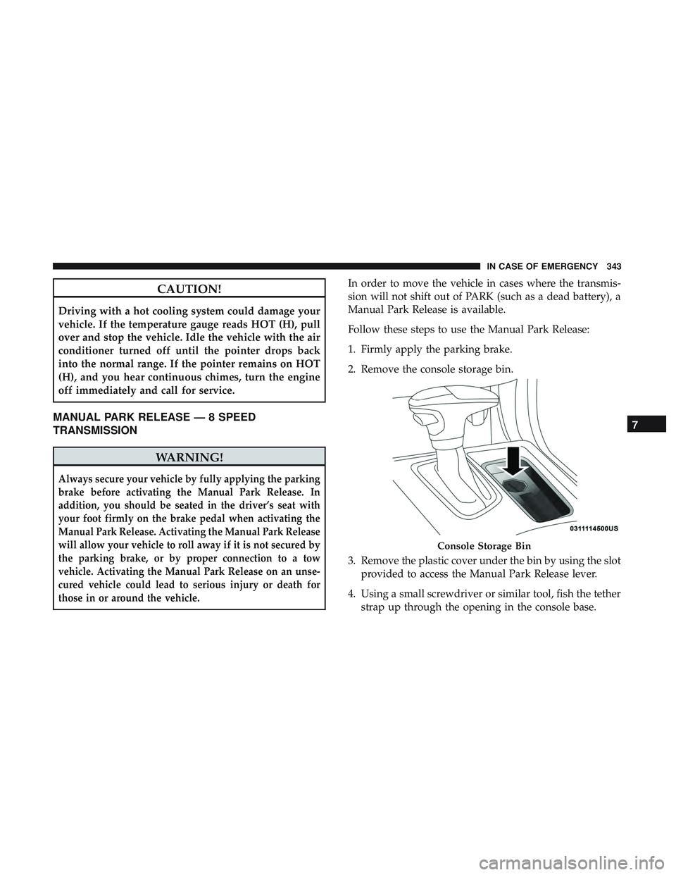
2. Remove the console storage bin.
3. Remove the plastic cover under the bin by using the slotprovided to access the Manual Park Release lever.
4. Using a small screwdriver or similar tool, fish the tether strap up through the opening in the console base.
Console Storage Bin
7
IN CASE OF EMERGENCY 343