Page 322 of 516
•Check the fluid levels of the coolant reservoir, brake
master cylinder, and power steering (if equipped) and
fill as needed.
• Check function of all interior and exterior lights.
Maintenance Plan — 3.6L And 5.7L
Required Maintenance Intervals
Refer to the maintenance chart for the required mainte-
nance intervals.
At Every Oil Change Interval As Indicated By Oil
Change Indicator System:
•Change oil and filter
• Rotate the tires.
Rotate at the first sign of irregular
wear, even if it occurs before your next scheduled
service
At Every Oil Change Interval As Indicated By Oil Change Indicator System:
•Inspect battery and clean and tighten terminals as
required
• Inspect brake pads, shoes, rotors, drums, hoses and
park brake
• Inspect engine cooling system protection and hoses
• Inspect exhaust system
• Inspect engine air cleaner if using in dusty or
off-road conditions
320 SERVICING AND MAINTENANCE
Page 327 of 516

•Under no circumstances should oil change intervals
exceed 6,000 miles (10,000 km) or six months, whichever
comes first.
Your authorized dealer will reset the oil change indicator
message after completing the scheduled oil change. If a
scheduled oil change is performed by someone other than
your authorized dealer, the message can be reset by
referring to the steps described under “Instrument Cluster
Display” in “Getting To Know Your Instrument Panel” for
further information.
At Each Stop For Fuel
• Check the engine oil level. Refer to “Engine Compart-
ment” in this chapter for further information.
• Check the windshield washer solvent and add if re-
quired. Once A Month
•
Check tire pressure and look for unusual wear or
damage.
• Inspect the battery, and clean and tighten the terminals
as required.
• Check the fluid levels of the coolant reservoir, brake
master cylinder, and add as needed.
• Check all lights and other electrical items for correct
operation.
At Each Oil Change
• Change the engine oil filter.
• Inspect the brake hoses and lines.
CAUTION!
Failure to perform the required maintenance items
may result in damage to the vehicle.
8
SERVICING AND MAINTENANCE 325
Page 355 of 516

If an examination of your engine compartment shows no
evidence of radiator or hose leaks, the vehicle may be
safely driven. The vapor will soon dissipate.
•Do not overfill the coolant expansion bottle.
• Check the coolant freeze point in the radiator and in the
coolant expansion bottle. If engine coolant (antifreeze)
needs to be added, the contents of the coolant expansion
bottle must also be protected against freezing.
• If frequent engine coolant (antifreeze) additions are
required, the cooling system should be pressure tested
for leaks.
• Maintain engine coolant (antifreeze) concentration at a
minimum of 50% OAT coolant (conforming to
MS.90032) and distilled water for proper corrosion pro-
tection of your engine which contains aluminum com-
ponents.
• Make sure that the coolant expansion bottle overflow
hoses are not kinked or obstructed.
• Keep the front of the radiator clean. If your vehicle is
equipped with air conditioning, keep the front of the
condenser clean.
• Do not change the thermostat for Summer or Winter
operation. If replacement is ever necessary, install ONLY the correct type thermostat. Other designs may result in
unsatisfactory engine coolant (antifreeze) performance,
poor gas mileage, and increased emissions.
Brake System
In order to assure brake system performance, all brake
system components should be inspected periodically. Refer
to the “Maintenance Plan” in this section for the proper
maintenance intervals.
WARNING!
Riding the brakes can lead to brake failure and possi-
bly a collision. Driving with your foot resting or riding
on the brake pedal can result in abnormally high brake
temperatures, excessive lining wear, and possible
brake damage. You would not have your full braking
capacity in an emergency.
Fluid Level Check — Brake Master Cylinder
Check the fluid level in the master cylinder immediately if
the brake system warning light indicates system failure.
Check the fluid level in the master cylinder when perform-
ing underhood services.
8
SERVICING AND MAINTENANCE 353
Page 359 of 516

Routine fluid and filter changes are not required. However,
change the fluid and filter if the fluid becomes contami-
nated (with water, etc.), or if the transmission is disas-
sembled for any reason.
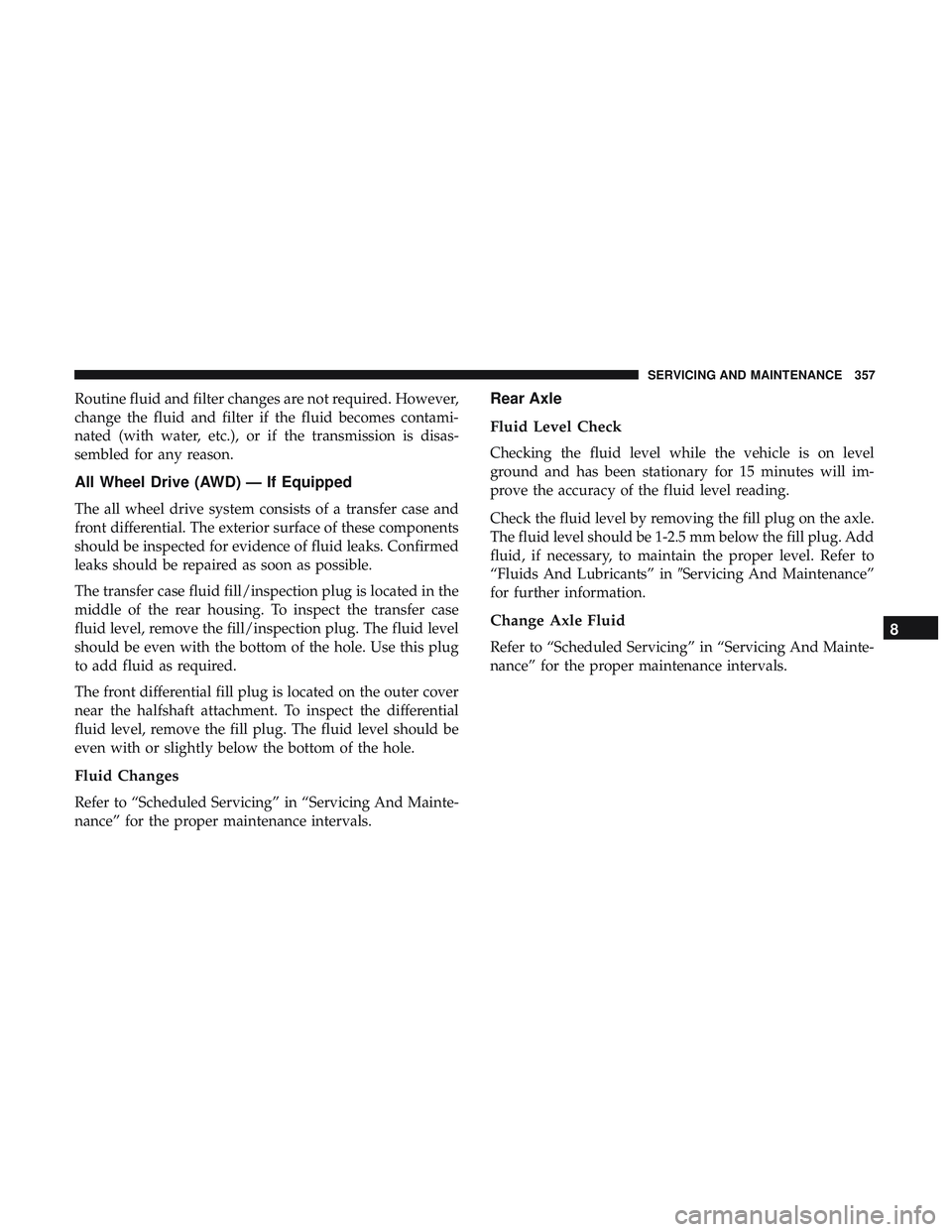
All Wheel Drive (AWD) — If Equipped
The all wheel drive system consists of a transfer case and
front differential. The exterior surface of these components
should be inspected for evidence of fluid leaks. Confirmed
leaks should be repaired as soon as possible.
The transfer case fluid fill/inspection plug is located in the
middle of the rear housing. To inspect the transfer case
fluid level, remove the fill/inspection plug. The fluid level
should be even with the bottom of the hole. Use this plug
to add fluid as required.
The front differential fill plug is located on the outer cover
near the halfshaft attachment. To inspect the differential
fluid level, remove the fill plug. The fluid level should be
even with or slightly below the bottom of the hole.
Fluid Changes
Refer to “Scheduled Servicing” in “Servicing And Mainte-
nance” for the proper maintenance intervals.
Rear Axle
Fluid Level Check
Checking the fluid level while the vehicle is on level
ground and has been stationary for 15 minutes will im-
prove the accuracy of the fluid level reading.
Check the fluid level by removing the fill plug on the axle.
The fluid level should be 1-2.5 mm below the fill plug. Add
fluid, if necessary, to maintain the proper level. Refer to
“Fluids And Lubricants” in�Servicing And Maintenance”
for further information.
Change Axle Fluid
Refer to “Scheduled Servicing” in “Servicing And Mainte-
nance” for the proper maintenance intervals.
8
SERVICING AND MAINTENANCE 357
Page 361 of 516

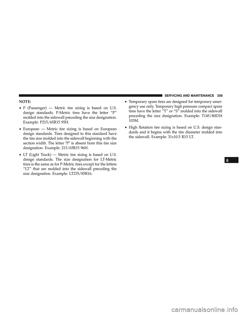
NOTE:
•P (Passenger) — Metric tire sizing is based on U.S.
design standards. P-Metric tires have the letter “P”
molded into the sidewall preceding the size designation.
Example: P215/65R15 95H.
• European — Metric tire sizing is based on European
design standards. Tires designed to this standard have
the tire size molded into the sidewall beginning with the
section width. The letter �P�is absent from this tire size
designation. Example: 215/65R15 96H.
• LT (Light Truck) — Metric tire sizing is based on U.S.
design standards. The size designation for LT-Metric
tires is the same as for P-Metric tires except for the letters
“LT” that are molded into the sidewall preceding the
size designation. Example: LT235/85R16. •
Temporary spare tires are designed for temporary emer-
gency use only. Temporary high pressure compact spare
tires have the letter “T” or “S” molded into the sidewall
preceding the size designation. Example: T145/80D18
103M.
• High flotation tire sizing is based on U.S. design stan-
dards and it begins with the tire diameter molded into
the sidewall. Example: 31x10.5 R15 LT.
8
SERVICING AND MAINTENANCE 359
Page 362 of 516
Tire Sizing Chart
EXAMPLE:
Example Size Designation: P215/65R15XL 95H, 215/65R15 96H, LT235/85R16C, T145/80D18 103M, 31x10.5 R15 LT
P = Passenger car tire size based on U.S. design standards, or
�....blank....� = Passenger car tire based on European design standards, or
LT = Light truck tire based on U.S. design standards, or
TorS= Temporary spare tire or
31 = Overall diameter in inches (in)
215, 235, 145 = Section width in millimeters (mm)
65, 85, 80 = Aspect ratio in percent (%)
–Ratio of section height to section width of tire, or
10.5 = Section width in inches (in)
R = Construction code
–�R� means radial construction, or
–�D� means diagonal or bias construction
15, 16, 18 = Rim diameter in inches (in)
360 SERVICING AND MAINTENANCE
Page 363 of 516

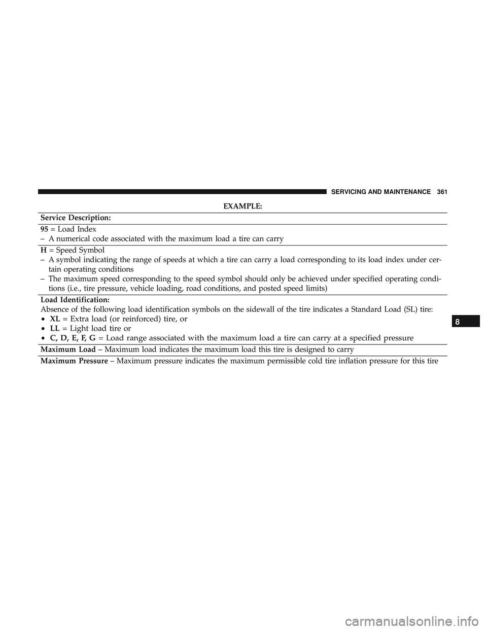
EXAMPLE:
Service Description:
95 = Load Index
–A numerical code associated with the maximum load a tire can carry
H = Speed Symbol
–A symbol indicating the range of speeds at which a tire can carry a load corresponding to its load index under cer-
tain operating conditions
–The maximum speed corresponding to the speed symbol should only be achieved under specified operating condi-
tions (i.e., tire pressure, vehicle loading, road conditions, and posted speed limits)
Load Identification:
Absence of the following load identification symbols on the sidewall of the tire indicates a Standard Load (SL) tire:
• XL = Extra load (or reinforced) tire, or
• LL = Light load tire or
• C, D, E, F, G = Load range associated with the maximum load a tire can carry at a specified pressure
Maximum Load – Maximum load indicates the maximum load this tire is designed to carry
Maximum Pressure – Maximum pressure indicates the maximum permissible cold tire inflation pressure for this tire
8
SERVICING AND MAINTENANCE 361
Page 375 of 516

WARNING!(Continued)
You could lose control and have a collision resulting in
serious injury or death.
Keep dismounted tires in a cool, dry place with as little
exposure to light as possible. Protect tires from contact with
oil, grease, and gasoline.
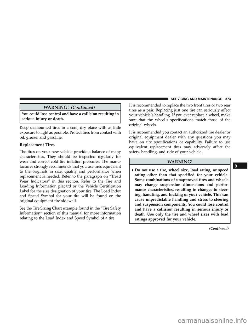
Replacement Tires
The tires on your new vehicle provide a balance of many
characteristics. They should be inspected regularly for
wear and correct cold tire inflation pressures. The manu-
facturer strongly recommends that you use tires equivalent
to the originals in size, quality and performance when
replacement is needed. Refer to the paragraph on “Tread
Wear Indicators” in this section. Refer to the Tire and
Loading Information placard or the Vehicle Certification
Label for the size designation of your tire. The Load Index
and Speed Symbol for your tire will be found on the
original equipment tire sidewall.
See the Tire Sizing Chart example found in the “Tire Safety
Information” section of this manual for more information
relating to the Load Index and Speed Symbol of a tire. It is recommended to replace the two front tires or two rear
tires as a pair. Replacing just one tire can seriously affect
your vehicle’s handling. If you ever replace a wheel, make
sure that the wheel’s specifications match those of the
original wheels.
It is recommended you contact an authorized tire dealer or
original equipment dealer with any questions you may
have on tire specifications or capability. Failure to use
equivalent replacement tires may adversely affect the
safety, handling, and ride of your vehicle.
WARNING!
•
Do not use a tire, wheel size, load rating, or speed
rating other than that specified for your vehicle.
Some combinations of unapproved tires and wheels
may change suspension dimensions and perfor-
mance characteristics, resulting in changes to steer-
ing, handling, and braking of your vehicle. This can
cause unpredictable handling and stress to steering
and suspension components. You could lose control
and have a collision resulting in serious injury or
death. Use only the tire and wheel sizes with load
ratings approved for your vehicle.
(Continued)
8
SERVICING AND MAINTENANCE 373