Page 233 of 516

To increase the distance setting, push the Distance Setting —
Increase button and release. Each time the button is pushed,
the distance setting increases by one bar (longer).
To decrease the distance setting, push the Distance Setting —
Decrease button and release. Each time the button is pushed,
the distance setting decreases by one bar (shorter).
If there is no vehicle ahead, the vehicle will maintain the set
speed. If a slower moving vehicle is detected in the same
lane, the instrument cluster display will show the “SensedVehicle Indicator” icon, and the system adjusts vehicle
speed automatically to maintain the distance setting, re-
gardless of the set speed.
The vehicle will then maintain the set distance until:
•
The vehicle ahead accelerates to a speed above the set
speed.
• The vehicle ahead moves out of your lane or view of the
sensor.
• The distance setting is changed.
• The system disengages. (Refer to the information on
ACC Activation).
The maximum braking applied by ACC is limited; how-
ever, the driver can always apply the brakes manually, if
necessary.
NOTE: The brake lights will illuminate whenever the ACC
system applies the brakes.
A Proximity Warning will alert the driver if ACC predicts
that its maximum braking level is not sufficient to maintain
the set distance. If this occurs, a visual alert “BRAKE” will
flash in the instrument cluster display and a chime will
sound while ACC continues to apply its maximum braking
capacity.
Distance Setting 1 Bar (Short)
6
STARTING AND OPERATING 231
Page 241 of 516
To Set A Desired Speed
Turn the Normal (Fixed Speed) Cruise Control
on. When the vehicle has reached the desired
speed, push the SET (+) or SET (-) button and
release. Release the accelerator and the vehicle
will operate at the selected speed. Once a speed has been
set a message “CRUISE CONTROL SET TO MPH (km/h)”
will appear indicating what speed was set. This light will
turn on when the system is turned on via the on/off
control. It turns green when the cruise control is set.
To Vary The Speed Setting
To Increase Speed
When the Normal (Fixed Speed) Cruise Control is set, you
can increase speed by pushing the SET (+)button.
The driver’s preferred units can be selected through the
instrument cluster display. Refer to “Getting To Know Your
Instrument Panel” for more information. The speed incre-
ment shown is dependant on the speed of U.S. (mph) or
Metric (km/h) units: U.S. Speed (mph)
•
Pushing the SET (+)button once will result ina1mph
increase in set speed. Each subsequent tap of the button
results in an increase of 1 mph.
• If the button is continually pushed, the set speed will
continue to increase in 5 mph increments until the
button is released. The increase in set speed is reflected
in the instrument cluster display.
Metric Speed (km/h)
• Pushing the SET (+)button once will result in a 1 km/h
increase in set speed. Each subsequent tap of the button
results in an increase of 1 km/h.
• If the button is continually pushed, the set speed will
continue to increase in 10 km/h increments until the
button is released. The increase in set speed is reflected
in the instrument cluster display.
To Decrease Speed
When the Normal (Fixed Speed) Cruise Control is set, you
can decrease speed by pushing the SET (-)button.
The driver’s preferred units can be selected through the
instrument cluster display. Refer to “Getting To Know Your
6
STARTING AND OPERATING 239
Page 252 of 516
REFUELING THE VEHICLE
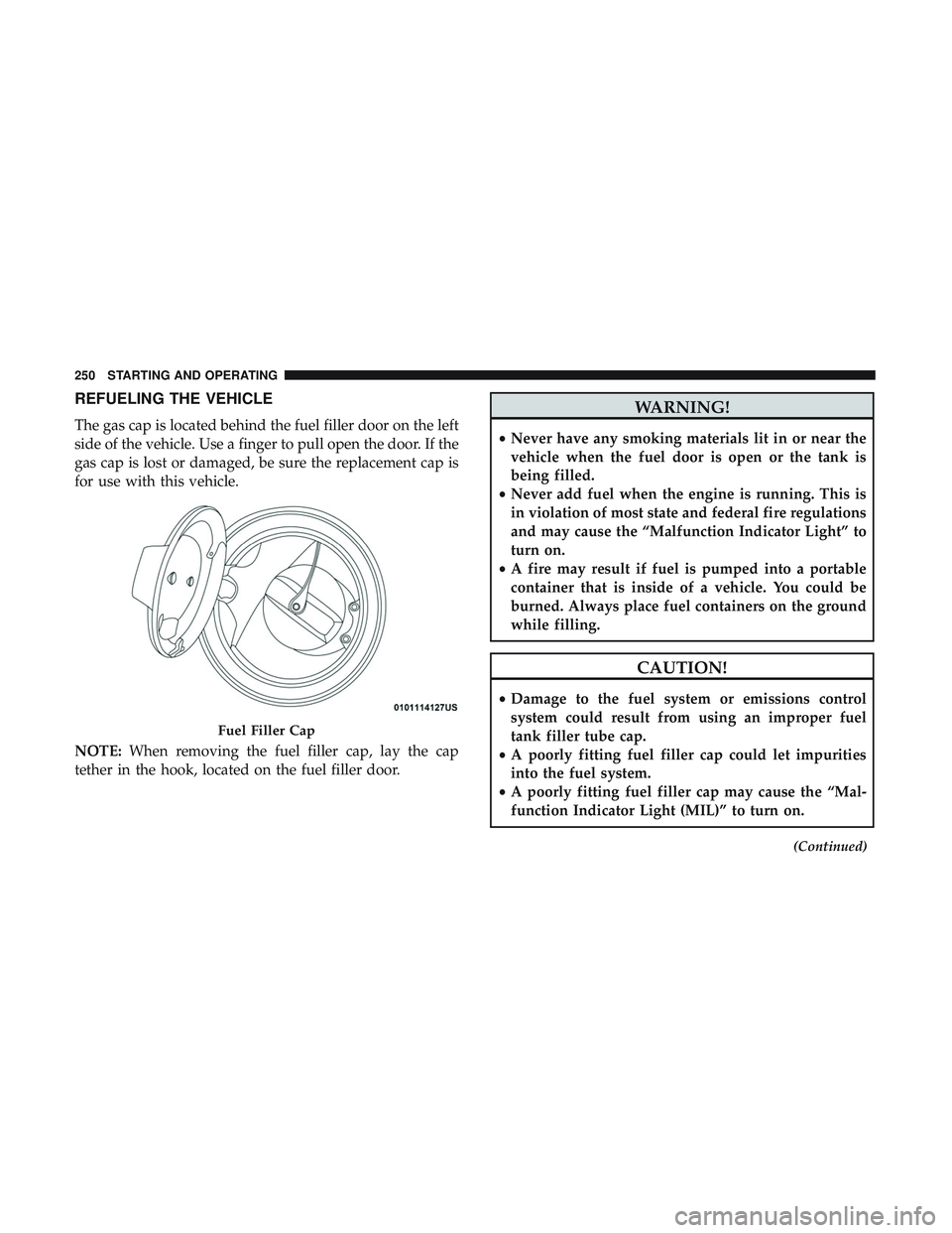
The gas cap is located behind the fuel filler door on the left
side of the vehicle. Use a finger to pull open the door. If the
gas cap is lost or damaged, be sure the replacement cap is
for use with this vehicle.
NOTE:When removing the fuel filler cap, lay the cap
tether in the hook, located on the fuel filler door.
WARNING!
• Never have any smoking materials lit in or near the
vehicle when the fuel door is open or the tank is
being filled.
• Never add fuel when the engine is running. This is
in violation of most state and federal fire regulations
and may cause the “Malfunction Indicator Light” to
turn on.
• A fire may result if fuel is pumped into a portable
container that is inside of a vehicle. You could be
burned. Always place fuel containers on the ground
while filling.
CAUTION!
• Damage to the fuel system or emissions control
system could result from using an improper fuel
tank filler tube cap.
• A poorly fitting fuel filler cap could let impurities
into the fuel system.
• A poorly fitting fuel filler cap may cause the “Mal-
function Indicator Light (MIL)” to turn on.
(Continued)
Fuel Filler Cap
250 STARTING AND OPERATING
Page 258 of 516
Trailer Hitch Classification
The following chart provides the industry standard for the
maximum trailer weight a given trailer hitch class can tow
and should be used to assist you in selecting the correct
trailer hitch for your intended towing condition.
Trailer Hitch Classification Definitions
Class Max. Trailer Hitch Industry Standards
Class I - Light Duty 2,000 lbs (907 kg)
Class II - Medium Duty 3,500 lbs (1,587 kg)
Class III - Heavy Duty 5,000 lbs (2,267 kg)
Class IV - Extra Heavy Duty 10,000 lbs (4,535 kg)
Refer to the “Trailer Towing Weights (Maximum Trailer Weight Ratings)” chart for the Maximum Gross Trailer Weight
(GTW) towable for your given drivetrain.
All trailer hitches should be professionally installed on your vehicle.
Trailer Towing Weights (Maximum Trailer Weight Ratings)
Engine/Transmission Frontal AreaMax. GTW (Gross Trailer
Wt.) Max. Tongue Wt.
3.6L Automatic 12 sq ft (1.11 sq m) 1,000 lbs (454 kg) 100 lbs (45 kg)
5.7L Automatic 12 sq ft (1.11 sq m) 1,000 lbs (454 kg) 100 lbs (45 kg)
Refer to local laws for maximum trailer towing speeds.
Trailer towing with the 6.4L engine is not recommended.
256 STARTING AND OPERATING
Page 262 of 516

CAUTION!(Continued)
be of adequate capacity. Failure to do this could lead to
accelerated brake lining wear, higher brake pedal
effort, and longer stopping distances.
Towing Requirements — Trailer Lights And Wiring
Whenever you pull a trailer, regardless of the trailer size,
stoplights and turn signals on the trailer are required for
motoring safety.
The Trailer Tow Package may include a four- and seven-pin
wiring harness. Use a factory approved trailer harness and
connector.
NOTE:Do not cut or splice wiring into the vehicle’s wiring
harness.
The electrical connections are all complete to the vehicle
but you must mate the harness to a trailer connector. Refer
to the following illustrations. NOTE:
•
Disconnect trailer wiring connector from the vehicle
before launching a boat (or any other device plugged
into vehicle’s electrical connect) into water.
• Be sure to reconnect after clear from water area.
Four-Pin Connector
1 — Female Pins 4 — Park
2 — Male Pin 5 — Left Stop/Turn
3 — Ground 6 — Right Stop/Turn
260 STARTING AND OPERATING
Page 263 of 516
Towing Tips
Before setting out on a trip, practice turning, stopping, and
backing up the trailer in an area located away from heavy
traffic.
Automatic Transmission — If Equipped
Select the DRIVE range when towing. The transmission
controls include a drive strategy to avoid frequent shifting
when towing. However, if frequent shifting does occur
while in DRIVE, you can use the AutoStick shift control to
manually select a lower gear.
NOTE:Using a lower gear while operating the vehicle
under heavy loading conditions will improve performance
and extend transmission life by reducing excessive shifting
and heat buildup. This action will also provide better
engine braking.
Speed Control — If Equipped
• Do not use on hilly terrain or with heavy loads.
• When using the speed control, if you experience speed
drops greater than 10 mph (16 km/h), disengage until
you can get back to cruising speed.
• Use speed control in flat terrain and with light loads to
maximize fuel efficiency.
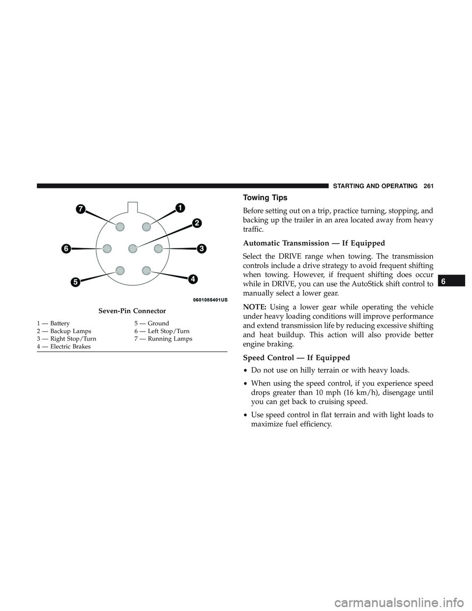
Seven-Pin Connector
1 — Battery 5 — Ground
2 — Backup Lamps 6 — Left Stop/Turn
3 — Right Stop/Turn 7 — Running Lamps
4 — Electric Brakes
6
STARTING AND OPERATING 261
Page 266 of 516

Driving Through Water
Driving through water more than a few inches/centimeters
deep will require extra caution to ensure safety and pre-
vent damage to your vehicle.
Flowing/Rising Water
WARNING!
Do not drive on or across a road or path where water is
flowing and/or rising (as in storm run-off). Flowing
water can wear away the road or path’s surface and
cause your vehicle to sink into deeper water. Further-
more, flowing and/or rising water can carry your ve-
hicle away swiftly. Failure to follow this warning may
result in injuries that are serious or fatal to you, your
passengers, and others around you.
Shallow Standing Water
Although your vehicle is capable of driving through shal-
low standing water, consider the following Cautions and
Warnings before doing so.
WARNING!
•Driving through standing water limits your vehicle’s
traction capabilities. Do not exceed 5 mph (8 km/h)
when driving through standing water.
• Driving through standing water limits your vehicle’s
braking capabilities, which increases stopping dis-
tances. Therefore, after driving through standing
water, drive slowly and lightly press on the brake
pedal several times to dry the brakes.
• Failure to follow these warnings may result in inju-
ries that are serious or fatal to you, your passengers,
and others around you.
264 STARTING AND OPERATING
Page 272 of 516
WARNING!(Continued)
SiriusXM Guardian features and applications in this
vehicle. Only use Uconnect features and SiriusXM
Guardian services when it is safe to do so. Failure to do
so may result in an accident involving serious injury or
death.
NOTE:
• Your vehicle may be transmitting data as authorized by
the subscriber.
• The SOS and ASSIST buttons will only function if you
are connected to an operable LTE (voice/data) or 4G
(data) network. Other Uconnect services will only be
operable if your SiriusXM Guardian service is active and
you are connected to an operable LTE (voice/data) or 4G
(data) network.
ASSIST Call
The ASSIST Button is used to automatically connect you to
any one of the following support centers:
• Roadside Assistance – If you get a flat tire, or need a tow,
just push the ASSIST button and you’ll be connected to someone who can help. Roadside Assistance will know
what vehicle you’re driving and its location. Additional
fees may apply for roadside Assistance.
• SiriusXM Guardian Customer Care – In-vehicle support
for SiriusXM Guardian.
• Vehicle Customer Care – Total support for all other
vehicle issues.
SOS Call
1. Push the SOS Call button on the Rearview Mirror.
NOTE: In case the SOS Call button is pushed in error, there
will be a ten second delay before the SOS Call system
initiates a call to a SOS operator. To cancel the SOS Call
connection, push the SOS call button on the Rearview
Mirror or press the cancellation button on the Device
Screen. Termination of the SOS Call will turn off the green
LED light on the Rearview Mirror.
2. The LED light located between the ASSIST and SOS buttons on the Rearview Mirror will turn green once a
connection to a SOS operator has been made.
270 IN CASE OF EMERGENCY