2018 CITROEN DS3 tow
[x] Cancel search: towPage 171 of 248

169
If a pressure of 2 bars is not reached after
7 minutes, this indicates that the tyre is
not repairable; contact your dealer or
a
qualified workshop for recovery.
F
O
nce the correct pressure is reached, put
the switch to the " O" position.
F
R
emove the kit then stow it.
Do not drive more than 120
miles (200 km)
with a
temporarily repaired tyre; see your
dealer or a
qualified workshop to change
the tyre.
Should the pressure of one or more tyres
be adjusted, it is necessary to reinitialise
the under-inflation detection system.
For more information on Under-inflation
detection , refer to the corresponding
section.
Spare wheel
Scan the QR code on page 3 to view
e xplanatory videos.
Procedure for changing a
damaged wheel with
the spare wheel using the tools provided with
the vehicle.
Access to the tools
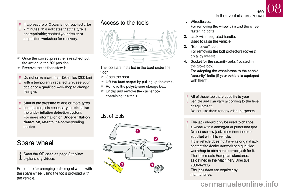
List of tools
1. Wheelbrace.
For removing the wheel trim and the wheel
fastening bolts.
2. Jack with integrated handle.
Used to raise the vehicle.
3. "Bolt cover" tool.
For removing the bolt protectors (covers)
on alloy wheels.
4. Socket for the security bolts (located in
the glove box).
For adapting the wheelbrace to the special
"security" bolts (if your vehicle is equipped
with them).
All of these tools are specific to your
vehicle and can vary according to the level
of equipment.
Do not use them for any other purposes.
The jack should only be used to change
a
wheel with a damaged or punctured tyre.
Do not use any jack other than the one
supplied with this vehicle.
If the vehicle does not have its original jack,
contact the dealer network or a
qualified
workshop to obtain the correct jack for it.
The jack meets European standards,
as defined in the Machinery Directive
2006/42/EC.
The jack does not require any
maintenance.
The tools are installed in the boot under the
f l o o r.
F
O
pen the boot.
F
L
ift the boot carpet by pulling up the strap.
F
R
emove the polystyrene storage box.
F
U
nclip and remove the carrier box
containing the tools.
08
In the event of a breakdown
Page 172 of 248

170
Access to the spare wheel
Taking out the wheelPutting the wheel back in place
The spare wheel is located in the boot under
t h e f l o o r.
Depending on the country of sale, you will
have a "space-saver" type spare wheel or
a
temporary puncture repair kit.
F
U
nscrew the central nut.
F
R
emove the fastening device (nut and bolt). F
R
aise the spare wheel towards you from the
r e a r.
F
T
ake the wheel out of the boot.
On vehicles with a "space-saver" type
spare wheel, the punctured tyre can
replace the "space-saver" wheel; however,
the boot floor will no longer be even.
F
P
ut the wheel back in its housing.
F
S
lacken the nut on the bolt by a few turns.
F
P
osition the fastening device (nut and bolt)
in the middle of the wheel.
F
T
ighten fully until the central nut clicks, to
retain the wheel correctly. F
P
ut the carrier box back in place in the
centre of the wheel and clip it.
F
P
ut the polystyrene storage box back in
place.
F
R
eposition the carpet at the back of the boot
by folding it gently in two.
08
In the event of a breakdown
Page 174 of 248

172
On vehicles equipped with body sill
mouldings, the location of the jack
contact area is indicated by a mark on the
moulding. It is essential that the jack be
placed in line with this mark, in the jack
contact area, located behind the moulding
and not on the plastic moulding.
F
E
xtend the jack 2 until its head comes into
contact with the jacking point A or B used;
the contact area A or B on the vehicle must
be correctly inserted into the central part of
the head of the jack.
F
Ra
ise the vehicle until there is sufficient
space between the wheel and the ground to
then allow the spare (not punctured) wheel
to fit easily. Stowing the damaged wheel
The damaged wheel can be stowed under
the floor, in the standard spare wheel
housing.
To stow an alloy wheel, first remove the
hub cap from the middle of the wheel so
that the fastening device (nut and bolt) can
be put in place.
In the case of a "space-saver" type spare
wheel, the damaged wheel cannot be
stowed under the floor. It must be stowed
in the boot; use a
cover to protect the
inside of the boot.
Refitting the wheel
F Place the foot of jack 2 on the ground and
ensure that it is directly below the front
A or rear B jacking point provided on the
underbody, whichever is closest to the
wheel to be changed.
F
R
emove the bolts and keep them in a clean
place.
F
R
emove the wheel.
08
In the event of a breakdown
Page 176 of 248

174
Changing a bulb
The headlamps have polycarbonate
lenses with a
protective coating:
F
d
o not clean them using a dr y or
abrasive cloth, nor with a
detergent
or solvent product,
F
u
se a sponge and soapy water or a pH
neutral product,
F
w
hen using a high pressure washer
on persistent marks, do not keep the
lance directed towards the lamps or
their edges for too long, so as not to
damage their protective coating and
seals.
Changing a
bulb must only be done with
the ignition off and after the headlamp has
been switched off for several minutes –
Risk of serious burns!
F
D
o not touch the bulb directly with your
fingers, use a
lint-free cloth.
It is essential only to use anti-ultraviolet
(UV) type bulbs, so as not to damage the
headlamp.
Always replace a
failed bulb with a new
bulb with the same type and specification.
Front lamps
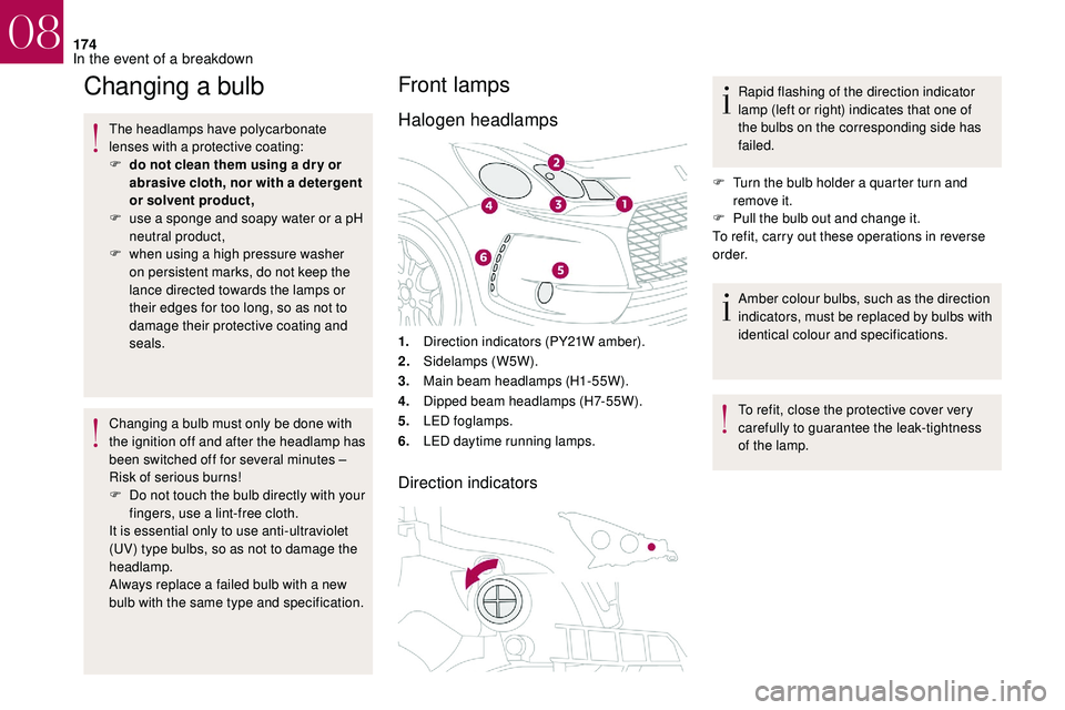
Halogen headlamps
1. Direction indicators (PY21W amber).
2. Sidelamps (W5W).
3. Main beam headlamps (H1-55W).
4. Dipped beam headlamps (H7-55W).
5. LED foglamps.
6. LED daytime running lamps.
Direction indicators
Rapid flashing of the direction indicator
lamp (left or right) indicates that one of
the bulbs on the corresponding side has
failed.
F
T
urn the bulb holder a quarter turn and
remove it.
F
P
ull the bulb out and change it.
To refit, carry out these operations in reverse
o r d e r.
Amber colour bulbs, such as the direction
indicators, must be replaced by bulbs with
identical colour and specifications.
To refit, close the protective cover very
carefully to guarantee the leak-tightness
of the lamp.
08
In the event of a breakdown
Page 178 of 248

176
Integrated direction indicator side
repeaters
Contact the dealer network or a qualified
w orkshop to obtain the module.
LED foglamps
LED daytime running lampsRear lamps
Model with conventional bulb lamps
1. Brake/sidelamps (P21/5W).
2. Sidelamps (P5W).
3. Direction indicators (PY21W amber).
4. Foglamp (PR21W red) or reversing lamp
(P21W ).
Model with rear 3D lamps
F Insert a screwdriver towards the centre of
the repeater between the repeater and the
base of the mirror.
F
L
ever with the screwdriver to extract the
repeater and pull it out.
F
D
isconnect the connector from the repeater.
F
R
eplace the module.
To refit, carry out these operations in reverse
o r d e r. For the replacement of this type of diode
lamp, contact the dealer network or a
qualified
workshop.
For the replacement of this type of diode
lamp, contact the dealer network or a
qualified
workshop. 1.
3D LED sidelamps.
2. LED brake/sidelamps.
08
In the event of a breakdown
Page 179 of 248

177
3.LED side marker lamps.
4. Direction indicators (PY21W amber).
5. Foglamp (H21W red) or reversing lamp
(H21W ).
Amber or red colour bulbs, such as the
direction indicators or foglamps, must be
replaced by bulbs with identical colour and
specifications.
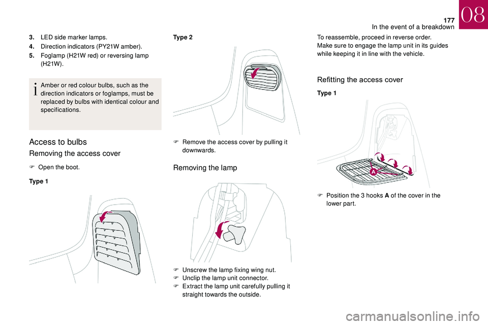
Access to bulbs
Removing the access cover
F Open the boot.
Ty p e 1 Ty p e 2Removing the lamp
To reassemble, proceed in reverse order.
Make sure to engage the lamp unit in its guides
while keeping it in line with the vehicle.
Refitting the access cover
Ty p e 1
F
R
emove the access cover by pulling it
downwards.
F
U
nscrew the lamp fixing wing nut.
F
U
nclip the lamp unit connector.
F
E
xtract the lamp unit carefully pulling it
straight towards the outside. F
P
osition the 3 hooks A of the cover in the
lower part.
08
In the event of a breakdown
Page 193 of 248

191
F switch off all electrical consumers (audio system, wipers, lighting, etc.),
F
s
witch off the ignition and wait for four
minutes.
Upon accessing the battery, you only need to
disconnect the positive (+) terminal.
Quick-release terminal clamp
Disconnecting the (+) terminal
F Raise the lever A fully to release the clamp B .
Reconnecting the (+) terminal
F Position the open clamp B of the cable on
the positive terminal (+) of the battery.
F
P
ress down on the clamp to position it
correctly against the battery.
F
L
ock the clamp by lowering the lever A .Do not force the lever as locking will be
impossible if the clamp is not positioned
correctly; start the procedure again.
After reconnecting the battery
After reconnecting the battery, switch on the
ignition and wait 1
minute before starting to
allow initialisation of the electronic systems.
If minor problems nevertheless persist
following this operation, contact the dealer
network or a
qualified workshop.
You must reinitialise or reset certain systems by
yourself, consulting the corresponding section,
such as:
-
t
he remote control key,
-
t
he electric windows,
-
t
he date and time,
-
t
he radio preset stations.The Stop & Start system may not be
operational during the trip following the
first engine start.
In this case, the system will only be
available again after a
continuous
period of immobilisation of the vehicle,
a period which depends on the exterior
temperature and the state of charge of the
battery (up to about 8
hours).
To w i n g
Procedure for having your vehicle towed or for
towing another vehicle using the towing eye.
Access to tools
The towing eye is stored in the boot under the
f l o o r.
To access it:
F
o
pen the boot,
F
r
aise the floor,
F
r
emove the polystyrene storage box,
F
r
emove the towing eye from the holder.
08
In the event of a breakdown
Page 194 of 248

192
General recommendations
Obser ve the legislation in force in your
c o u nt r y.
Ensure that the weight of the towing
vehicle is higher than that of the towed
vehicle.
The driver must remain at the wheel of
the towed vehicle and must have a valid
driving licence.
When towing a
vehicle with all four
wheels on the ground, always use an
approved towing arm; rope and straps are
prohibited.
The towing vehicle must move off gently.
When the vehicle is towed with its engine
off, there is no longer braking and steering
assistance.
In the following cases, you must always
call on a
professional recovery ser vice:
-
v
ehicle broken down on a motor way or
main road,
-
f
our-wheel drive vehicle,
-
w
hen it is not possible to put the
gearbox into neutral, unlock the
steering, or release the parking brake,
-
t
owing with only two wheels on the
ground,
-
w
here there is no approved towbar
available.Towing your vehicle
Failure to obser ve this instruction could
result in damage to certain components
(braking, transmission, etc.) and the
absence of braking assistance the next
time the engine is started. F
U
nlock the steering by turning the ignition
key one notch and release the parking
brake.
F
S
witch on the hazard warning lamps on
both vehicles.
F
S
et off gently and drive slowly for a short
distance.
Towing another vehicle
F In the front bumper, unclip the access cover by pulling successively on the two tabs,
using a
screwdriver.
F
T
urn the access cover.
F
R
emove the cover completely by pressing
the plastic diamond on the lower part.
F
P
lace the flap in the boot.
F
S
crew the towing eye in fully.
F
I
nstall the towbar.
F
M
ove the gear lever into neutral (position N
for an electronic or automatic gearbox). F
O
n the rear bumper, unclip the cover by
pressing at the bottom.
F
S
crew the towing eye in fully.
F
I
nstall the towbar.
F
S
witch on the hazard warning lamps on
both vehicles.
F
S
et off gently and drive slowly for a short
distance.
08
In the event of a breakdown