2018 CITROEN DISPATCH SPACETOURER steering
[x] Cancel search: steeringPage 234 of 400

232
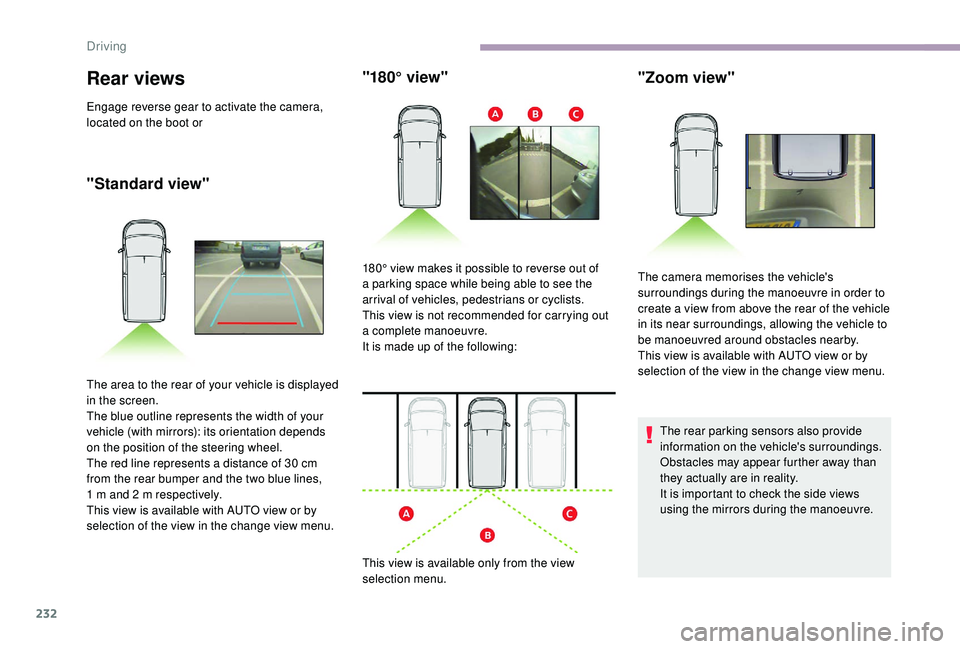
Rear views
Engage reverse gear to activate the camera,
located on the boot or
"Standard view""180° view"
The area to the rear of your vehicle is displayed
in the screen.
The blue outline represents the width of your
vehicle (with mirrors): its orientation depends
on the position of the steering wheel.
The red line represents a distance of 30
cm
from the rear bumper and the two blue lines,
1
m and 2 m respectively.
This view is available with AUTO view or by
selection of the view in the change view menu. 180° view makes it possible to reverse out of
a parking space while being able to see the
arrival of vehicles, pedestrians or cyclists.
This view is not recommended for carrying out
a complete manoeuvre.
It is made up of the following:
This view is available only from the view
selection menu.
The rear parking sensors also provide
information on the vehicle's surroundings.
Obstacles may appear further away than
they actually are in reality.
It is important to check the side views
using the mirrors during the manoeuvre.
"Zoom view"
The camera memorises the vehicle's
surroundings during the manoeuvre in order to
create a view from above the rear of the vehicle
in its near surroundings, allowing the vehicle to
be manoeuvred around obstacles nearby.
This view is available with AUTO view or by
selection of the view in the change view menu.
Driving
Page 236 of 400

234
Under-inflation detection
This system automatically monitors the tyre
pressure while driving.
The system monitors the pressure in all four
tyres, once the vehicle is moving.
It compares the information given by the
wheel speed sensors with reference values,
which must be reinitialised after ever y tyre
pressure adjustment or wheel change.
The system triggers an alert as soon as it
detects a drop in the pressure of one or more
tyres.
The tyre under-inflation detection system
does not replace the need for vigilance on
the part of the driver.
This system still requires you to check
the tyre inflation pressures (including
the spare wheel) every month as well as
before a long journey.
Driving with under-inflated tyres impairs
handling, extends braking distances and
causes early tyre wear, particularly in
adverse conditions (heavy loads, high
speeds, long journeys). Driving with under-inflated tyres
increases fuel consumption.
The tyre pressure specifications for your
vehicle can be found on the tyre pressure
label.
For more information on the
Identification markings , refer to the
corresponding section.
Tyre pressures should be checked when
the tyres are "cold" (vehicle stopped for
1
hour or after a journey of less than
6
miles (10 km) at moderate speeds).
Other wise (when hot), add 0.3
bar to the
pressures shown on the label.
Snow chains
The system does not have to be
reinitialised after fitting or removing snow
chains.
Spare wheel
The steel spare wheel does not have an
under-inflation detection sensor.
Under-inflation alert
This warning is indicated by fixed
illumination of the lamp, an audible
signal and, depending on the
equipment installed, a message
displayed on the screen.
F
R
educe speed immediately, avoid excessive
steering movements and sudden braking.
F
S
top the vehicle as soon as it is safe to do
so.
The loss of pressure detected does not
always cause visible bulging of the tyre.
Do not satisfy yourself with just a visual
check.
F
I
n the event of a puncture, use the
temporary puncture repair kit or the spare
wheel (depending on equipment),
or
F
i
f you have a compressor, such as the one
in the temporary puncture repair kit, check
the pressures of the four tyres when cold,
or
F
i
f it is not possible to make this check
immediately, drive carefully at reduced
speed.
Driving
Page 247 of 400

245
Closing
F Take the stay out of the support notch.
F C lip the stay in its housing.
F
L
ower the bonnet and release it near the
end of its travel.
F
P
ull on the bonnet to check that it has
latched correctly.
The cooling fan may star t after
switching off the engine: take care
with articles and clothing that might be
caught by the fan blades.
Because of the presence of electrical
equipment under the bonnet, it is
recommended that exposure to water
(rain, washing, etc.) be limited.
Engine
Diesel
The Diesel fuel system operates under
high pressure:
-
N
ever carry out any work on the
system yourself.
-
H
Di engines make use of advanced
technology.
Specialist knowledge is needed for any
work on the system, which can only be
assured by CITROËN dealers.
This engine is an example only. The location of the dipstick and engine oil filler cap, as well as the
priming pump may vary.
1.
Screenwash and headlamp wash
reservoir.
2. Engine coolant reservoir.
3. Engine oil filler cap.
4. Engine oil dipstick.
5. Priming pump.
6. Brake fluid filler cap.
7. Battery.
8. Remote earth point ("-" terminal).
9. Fusebox. 10.
Power steering fluid reservoir.
11. A i r f i l t e r.
7
Practical information
Page 249 of 400

247
Oil grade
Before topping up the oil or changing the oil,
check that the oil is the correct grade for your
engine and conforms to the manufacturer's
recommendations.
Topping up the engine oil level
The location of the oil filler cap is shown in the
corresponding underbonnet layout view.
F
U
nscrew the oil filler cap to access the filler
opening.
F
A
dd oil in small quantities, avoiding any
spills on engine components (risk of fire).
F
W
ait a few minutes before checking the
level again using the dipstick.
F
A
dd more oil if necessary.
F
A
fter checking the level, carefully refit the oil
filler cap and the dipstick in its tube.
After topping up the oil, the check when
switching on the ignition with the oil level
indicator in the instrument panel is not
valid during the 30
minutes after topping-
up.
Engine oil change
Refer to the manufacturer's service schedule
for details of the inter val for this operation.
In order to maintain the reliability of the engine
and emissions control system, never use
additives in the engine oil.
Brake fluid level
The brake fluid level should be close
to the "MA X" mark. If it is not, check
the brake pad wear.
Draining the circuit
Refer to the manufacturer’s service schedule
for details of the inter val for this operation.
Fluid specification
The fluid must conform to the manufacturer's
recommendations.
Power steering fluid level
The fluid level should be close to
the "MA X" mark. Verify this, with the
engine cool, by reading the level on
the filler neck.
Coolant level
Check the coolant level regularly.
It is normal to top up the fluid
between two services.
To ensure that the reading is correct, your
vehicle must be parked on a level sur face with
the engine cool.
The coolant level should be close to the "MA X"
mark but should never exceed it.
If the level is close to or below the "MIN" mark,
it is essential to top up.
A low coolant level presents a risk of serious
damage to your engine.
When the engine is warm, the temperature of
the coolant is regulated by the fan.
In addition, as the cooling system is
pressurised, wait at least one hour after
switching off the engine before carrying out any
work.
7
Practical information
Page 261 of 400

259
The vehicle's electric system allows the
connection of the compressor for long
enough to inflate a tyre after a puncture
repair.
Only use the two 12 V sockets, located at
the front , to connect your compressor.
Kit content description
C.Deflation button.
D. Pressure gauge (in bar and psi).
E. Compartment housing a cable with an
adaptor for a 12
V socket.
F. Sealant cartridge.
G. White pipe with cap for repair and
inflation.
H. Speed limit sticker.
The speed limit sticker must be affixed to
the vehicle's steering wheel to remind you
that a wheel is in temporary use.
Do not exceed a speed of 50
mph
(80
km/h) when driving with a tyre repaired
using this type of kit.Repair procedure
1. Sealant
F Turn selector A to the "sealant" position.
F
C
heck that switch B is in
position O.
Avoid removing any foreign bodies which
have penetrated into the tyre.
The tyre inflation pressures are given on
this label.
F
S
witch off the ignition.
A. "Sealant" or "Air" position selector.
B. On I/off O switch.
8
In the event of a breakdown
Page 283 of 400

281
FuseN° Rating
(A) Functions
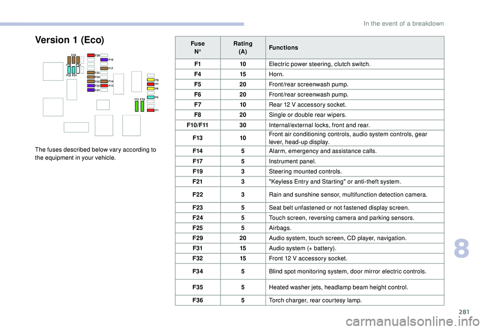
F1 10Electric power steering, clutch switch.
F4 15Horn.
F5 20Front/rear screenwash pump.
F6 20Front/rear screenwash pump.
F7 10Rear 12
V accessory socket.
F8 20Single or double rear wipers.
F10/F11 30Internal/external locks, front and rear.
F13 10Front air conditioning controls, audio system controls, gear
lever, head-up display.
F14 5Alarm, emergency and assistance calls.
F17 5Instrument panel.
F19 3Steering mounted controls.
F21 3"
K
eyless Entry and Starting" or anti-theft system.
F22 3Rain and sunshine sensor, multifunction detection camera.
F23 5Seat belt unfastened or not fastened display screen.
F24 5Touch screen, reversing camera and parking sensors.
F25 5Airbags.
F29 20Audio system, touch screen, CD player, navigation.
F31 15Audio system (+ battery).
F32 15Front 12
V accessory socket.
F34 5Blind spot monitoring system, door mirror electric controls.
F35 5Heated washer jets, headlamp beam height control.
F36 5Torch charger, rear courtesy lamp.Version 1 (Eco)
The fuses described below vary according to
the equipment in your vehicle.
8
In the event of a breakdown
Page 284 of 400

282
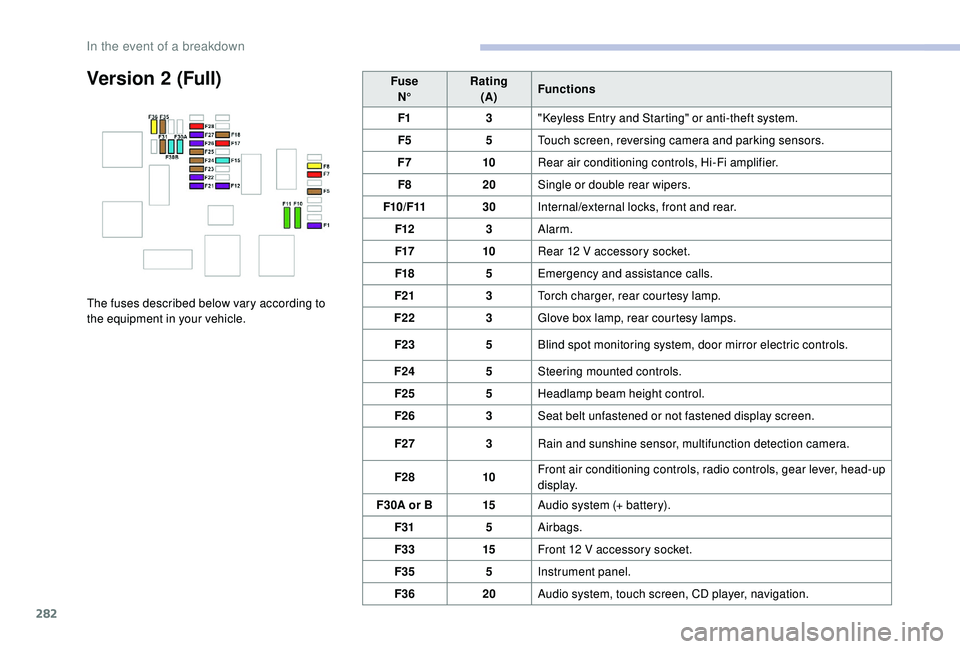
Version 2 (Full)
The fuses described below vary according to
the equipment in your vehicle.Fuse
N° Rating
(A) Functions
F1 3"
K
eyless Entry and Starting" or anti-theft system.
F5 5Touch screen, reversing camera and parking sensors.
F7 10Rear air conditioning controls, Hi-Fi amplifier.
F8 20Single or double rear wipers.
F10/F11 30Internal/external locks, front and rear.
F12 3Alarm.
F17 10Rear 12 V accessory socket.
F18 5Emergency and assistance calls.
F21 3Torch charger, rear courtesy lamp.
F22 3Glove box lamp, rear courtesy lamps.
F23 5Blind spot monitoring system, door mirror electric controls.
F24 5Steering mounted controls.
F25 5Headlamp beam height control.
F26 3Seat belt unfastened or not fastened display screen.
F27 3Rain and sunshine sensor, multifunction detection camera.
F28 10Front air conditioning controls, radio controls, gear lever, head-up
display.
F30A or B 15Audio system (+ battery).
F31 5Airbags.
F33 15Front 12
V accessory socket.
F35 5Instrument panel.
F36 20Audio system, touch screen, CD player, navigation.
In the event of a breakdown
Page 285 of 400

283
Engine compartment fuses
The fusebox is placed in the engine
compartment near the battery.
Access to the fuses
The fuses described hereafter vary according
to the equipment in your vehicle.
F
R
elease the two latches A .
F
R
emove the cover.
F
C
hange the fuse.
F
W
hen you have finished, close the cover
carefully then engage the two latches A , to
ensure correct sealing of the fusebox. Fuse
N° Rating
(A) Functions
F12 5Heated washer jets.
F14 25Front and rear screenwash pump.
F15 5Emergency braking front radar, electric power steering.
F17 10Built-in systems inter face.
F19 30Front wiper motor.
F20 15Front and rear screenwash pump.
F21 20Headlamp wash pump.
F22 15Horn.
F23 15Right-hand main beam headlamp.
F24 15Left-hand main beam headlamp.
8
In the event of a breakdown