2018 CHRYSLER PACIFICA mount
[x] Cancel search: mountPage 124 of 696
IconDescription
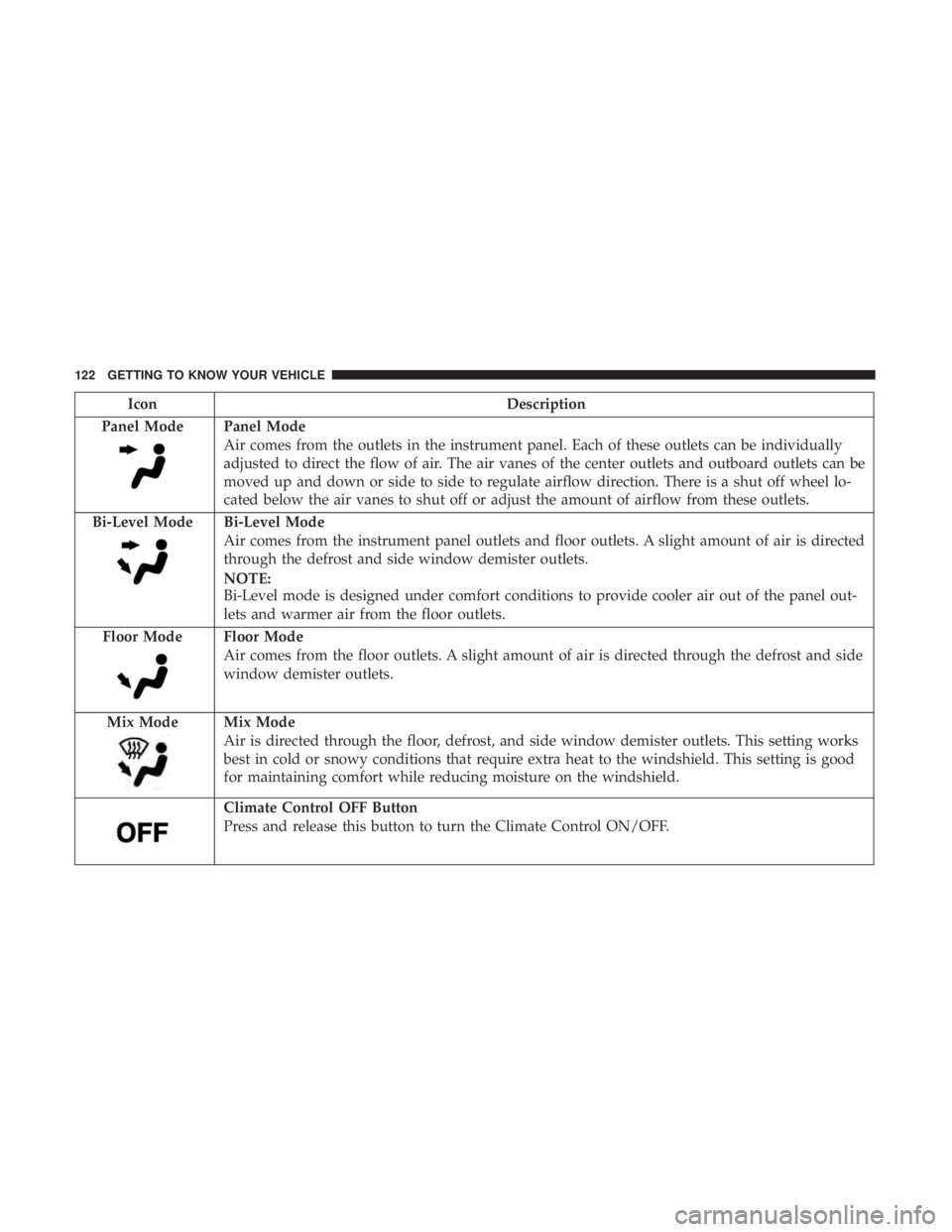
Panel Mode
Panel Mode
Air comes from the outlets in the instrument panel. Each of these outlets can be individually
adjusted to direct the flow of air. The air vanes of the center outlets and outboard outlets can be
moved up and down or side to side to regulate airflow direction. There is a shut off wheel lo-
cated below the air vanes to shut off or adjust the amount of airflow from these outlets.
Bi-Level Mode
Bi-Level Mode
Air comes from the instrument panel outlets and floor outlets. A slight amount of air is directed
through the defrost and side window demister outlets.
NOTE:
Bi-Level mode is designed under comfort conditions to provide cooler air out of the panel out-
lets and warmer air from the floor outlets.
Floor Mode
Floor Mode
Air comes from the floor outlets. A slight amount of air is directed through the defrost and side
window demister outlets.
Mix Mode
Mix Mode
Air is directed through the floor, defrost, and side window demister outlets. This setting works
best in cold or snowy conditions that require extra heat to the windshield. This setting is good
for maintaining comfort while reducing moisture on the windshield.
Climate Control OFF Button
Press and release this button to turn the Climate Control ON/OFF.
122 GETTING TO KNOW YOUR VEHICLE
Page 126 of 696
IconDescription
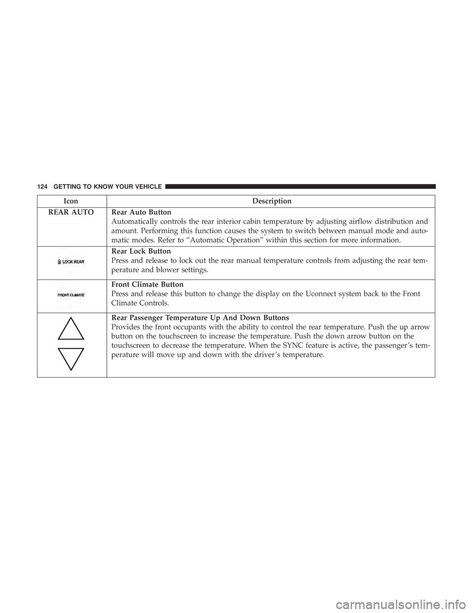
REAR AUTO Rear Auto Button Automatically controls the rear interior cabin temperature by adjusting airflow distribution and
amount. Performing this function causes the system to switch between manual mode and auto-
matic modes. Refer to “Automatic Operation” within this section for more information.
Rear Lock Button
Press and release to lock out the rear manual temperature controls from adjusting the rear tem-
perature and blower settings.
Front Climate Button
Press and release this button to change the display on the Uconnect system back to the Front
Climate Controls.
Rear Passenger Temperature Up And Down Buttons
Provides the front occupants with the ability to control the rear temperature. Push the up arrow
button on the touchscreen to increase the temperature. Push the down arrow button on the
touchscreen to decrease the temperature. When the SYNC feature is active, the passenger ’s tem-
perature will move up and down with the driver ’s temperature.
124 GETTING TO KNOW YOUR VEHICLE
Page 127 of 696
IconDescription
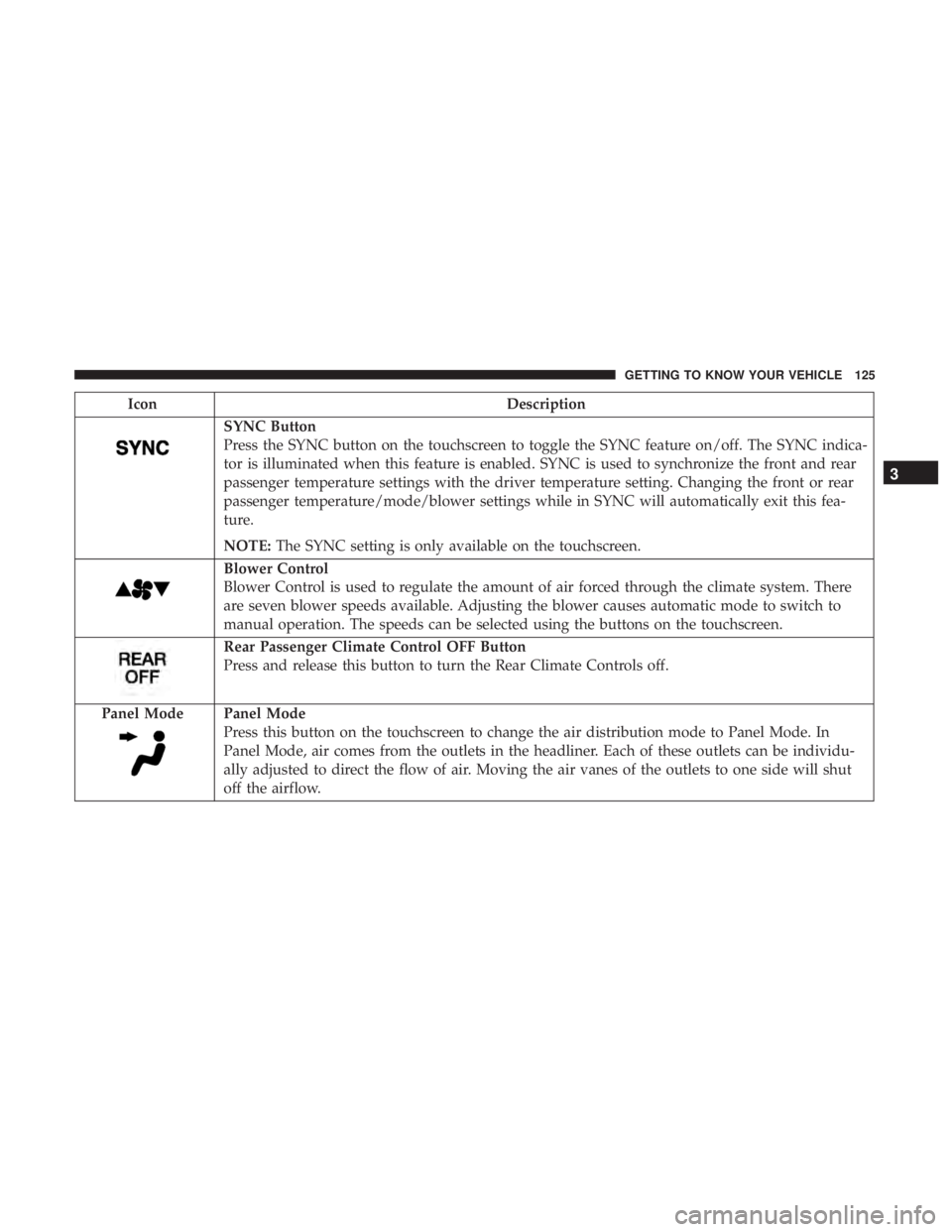
SYNC Button
Press the SYNC button on the touchscreen to toggle the SYNC feature on/off. The SYNC indica-
tor is illuminated when this feature is enabled. SYNC is used to synchronize the front and rear
passenger temperature settings with the driver temperature setting. Changing the front or rear
passenger temperature/mode/blower settings while in SYNC will automatically exit this fea-
ture.
NOTE:The SYNC setting is only available on the touchscreen.
Blower Control
Blower Control is used to regulate the amount of air forced through the climate system. There
are seven blower speeds available. Adjusting the blower causes automatic mode to switch to
manual operation. The speeds can be selected using the buttons on the touchscreen.
Rear Passenger Climate Control OFF Button
Press and release this button to turn the Rear Climate Controls off.
Panel Mode
Panel Mode
Press this button on the touchscreen to change the air distribution mode to Panel Mode. In
Panel Mode, air comes from the outlets in the headliner. Each of these outlets can be individu-
ally adjusted to direct the flow of air. Moving the air vanes of the outlets to one side will shut
off the airflow.
3
GETTING TO KNOW YOUR VEHICLE 125
Page 130 of 696
IconDescription
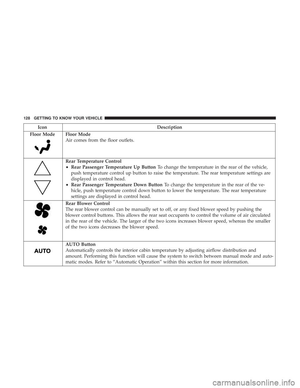
Floor Mode
Floor Mode
Air comes from the floor outlets.
Rear Temperature Control
•Rear Passenger Temperature Up Button To change the temperature in the rear of the vehicle,
push temperature control up button to raise the temperature. The rear temperature settings are
displayed in control head.
•Rear Passenger Temperature Down Button To change the temperature in the rear of the ve-
hicle, push temperature control down button to lower the temperature. The rear temperature
settings are displayed in control head.
Rear Blower Control
The rear blower control can be manually set to off, or any fixed blower speed by pushing the
blower control buttons. This allows the rear seat occupants to control the volume of air circulated
in the rear of the vehicle. The larger of the two icons increases blower speed, whereas the smaller
of the two icons decreases the blower speed.
AUTO Button
Automatically controls the interior cabin temperature by adjusting airflow distribution and
amount. Performing this function will cause the system to switch between manual mode and auto-
matic modes. Refer to “Automatic Operation” within this section for more information.
128 GETTING TO KNOW YOUR VEHICLE
Page 133 of 696

Winter Operation
To ensure the best possible heater and defroster perfor-
mance, make sure the engine cooling system is functioning
properly and the proper amount, type, and concentration
of coolant is used. Refer to “Fluids And Lubricants” in
“Technical Specifications” for proper coolant selection. Use
of the air Recirculation mode during Winter months is not
recommended, because it may cause window fogging.
Vacation/Storage
Before you store your vehicle, or keep it out of service (i.e.,
vacation) for two weeks or more, run the air conditioning
system at idle for about five minutes, in fresh air with the
blower setting on high. This will ensure adequate system
lubrication to minimize the possibility of compressor dam-
age when the system is started again.
Window Fogging
Vehicle windows tend to fog on the inside in mild, rainy,
and/or humid weather. To clear the windows, select De-
frost or Mix mode and increase the front blower speed. Do
not use the Recirculation mode without A/C for long
periods, as fogging may occur.
CAUTION!
Failure to follow these cautions can cause damage to
the heating elements:
•Use care when washing the inside of the rear win-
dow. Do not use abrasive window cleaners on the
interior surface of the window. Use a soft cloth and a
mild washing solution, wiping parallel to the heat-
ing elements. Labels can be peeled off after soaking
with warm water.
• Do not use scrapers, sharp instruments, or abrasive
window cleaners on the interior surface of the win-
dow.
• Keep all objects a safe distance from the window.
Outside Air Intake
Make sure the air intake, located directly in front of the
windshield, is free of obstructions such as leaves. Leaves
collected in the air intake may reduce airflow, and if they
enter the plenum, they could plug the water drains. In
winter months, make sure the air intake is clear of ice,
slush, and snow.
3
GETTING TO KNOW YOUR VEHICLE 131
Page 151 of 696
WARNING!
This equipment incorporates parts such as switches,
motors, or the like that tend to produce arcs or sparks
that can cause an explosion. When using your vacuum
near gasoline-dispensing equipment or service sta-
tions, park vehicle at least 20 ft (6 m) away from the
exterior enclosure of any dispensing pump. The
vacuum is mounted more than 18 inches (45 cm) above
ground level in your vehicle.
1. Before Using Vacuum:
Accessory (ACC) Mode Operation - For up to 10 minutes
of operation
Always apply the parking brake, shift the transmission into
PARK, and push ignition button to place ignition in
Accessory (ACC) mode. The engine will not be running in
this mode. Do not leave the key fob in or near the vehicle,
or in a location accessible to children.
NOTE: The vacuum system will run for 10 minutes off
battery power and then the vacuum will shut down. A low
battery indication light (LOW PWR) located below the
vacuum nozzle storage location will come on one minute
before the vacuum shuts down. Engine Running (ON) Operation - For more than 10
minutes of operation
•Position vehicle outdoors and fully open all side
windows.
• Always apply the parking brake, shift the transmission
into PARK, and leave engine running.
WARNING!
Carbon monoxide (CO) in exhaust gases can cause
serious injury or death. Follow the precautions below
to prevent carbon monoxide poisoning:
•Do not inhale exhaust gases.
• Do not start or run an engine in a closed garage or
confined area. Always position vehicle outdoors and
fully open all side windows before using vacuum
system with the engine running.
• Guard against carbon monoxide with proper main-
tenance. Have the exhaust system inspected every
time the vehicle is raised. Have any abnormal condi-
tions repaired promptly.
3
GETTING TO KNOW YOUR VEHICLE 149
Page 154 of 696
WARNING!(Continued)
•Do not allow to be used as a toy. Close attention is
necessary when used by or near children.
• Do not leave the vacuum running while unattended.
• Use only as described in this manual. Use only
attachments provided with your vehicle.
• Do not put any object into openings. Do not use with
any opening blocked; keep free of dust, lint, hair,
and anything that may reduce air flow.
• Do not vacuum toxic material such as chlorine
bleach, ammonia, drain cleaner, etc.
• Do not vacuum hard or sharp objects such as glass,
nails, screws, coins, etc.
• Keep hair, loose clothing, fingers, and all parts of
body away from openings and moving parts.
• Only use with filter in place. Periodically check that
the filter is in place and in good condition.
WARNING!
This equipment incorporates parts such as switches,
motors, or the like that tend to produce arcs or sparks
that can cause an explosion. When using your vacuum
(Continued)
WARNING! (Continued)
near gasoline-dispensing equipment or service sta-
tions, park vehicle at least 20 ft (6 m) away from the
exterior enclosure of any dispensing pump. The
vacuum is mounted more than 18 inches (45 cm) above
ground level in your vehicle.
5. When finished, push power button to turn vacuum off and store vacuum hose and any attachments.
6. Before exiting the vehicle: •If vehicle is in ACC mode, push ignition button to
place ignition in the OFF mode, remove key fob from
the vehicle, and lock the vehicle.
• If the engine is running, raise all of the windows, push
ignition button to place ignition in the OFF mode,
remove key fob from the vehicle, close all of the doors
and the liftgate and lock the vehicle.
Vacuum Troubleshooting
• DO NOT use with any opening blocked. If an object
becomes lodged in the hose, attempt to fully extend the
hose in a straight line while the vacuum motor is
running. If this does not dislodge the object, turn the
vacuum OFF and remove the hose from the vehicle
152 GETTING TO KNOW YOUR VEHICLE
Page 186 of 696
3. Speedometer•Indicates vehicle speed.
4. Fuel Gauge •The gauge shows the level of fuel in the fuel tank when
the ignition switch is in the ON/RUN position.
•
The fuel pump symbol points to the side of the
vehicle where the fuel door is located.
5. Temperature Gauge
•The temperature gauge shows engine coolant tem-
perature. Any reading within the normal range indi-
cates that the engine cooling system is operating
satisfactorily.
• The gauge can indicate a higher temperature when
driving in hot weather or up mountain grades. It
should not be allowed to exceed the upper limits of the
normal operating range.
WARNING!
Driving with a hot engine cooling system could dam-
age your vehicle. If the temperature gauge reaches “H”
pull over and stop the vehicle. Idle the vehicle with the
(Continued)
WARNING! (Continued)
air conditioner turned off until the gauge drops back
into the normal range and is no longer red. If the gauge
remains on the “H”, turn the engine off immediately
and call an authorized dealer for service.
WARNING!
A hot engine cooling system is dangerous. You or
others could be badly burned by steam or boiling
coolant. You may want to call an authorized dealer for
service if your vehicle overheats. If you decide to look
under the hood yourself, see “Servicing And Mainte-
nance”.
NOTE: The hard telltales will illuminate for a bulb check
when the ignition is first cycled.
184 GETTING TO KNOW YOUR INSTRUMENT PANEL