Page 132 of 614
Closing
To Close The Liftgate
Grasp the liftgate closing handle and initiate lowering the
liftgate. Release the handle when the liftgate takes over the
closing effort.
To Lock The Vehicle
With a valid Passive Entry key fob within 5 ft (1.5 m) of the
liftgate, pushing the passive entry lock button located to
the right of the outside handle will lock the vehicle.
WARNING!
•Driving with the liftgate open can allow poisonous
exhaust gases into your vehicle. You and your pas-
sengers could be injured by these fumes. Keep the
liftgate closed when you are operating the vehicle.
• If you are required to drive with the liftgate open,
make sure that all windows are closed, and the
climate control blower switch is set at high speed. Do
not use the recirculation mode.
Power Liftgate — If Equipped
The power liftgate may be opened or closed in several
ways:
• Overhead console liftgate button
• Key fob
• Outside handle (opens liftgate only)
• Button just inside the liftgate on the upper left trim
(when liftgate is open)
• Hands-Free Liftgate (opens liftgate only) — If Equipped
Using the above ways:
• When the liftgate is fully closed, the liftgate will open
• When the liftgate is fully open, the liftgate will close
• When the liftgate is moving, the liftgate will reverse
Push the Power Liftgate button on the Overhead Console
to open or close the liftgate.
Push the liftgate button on the key fob twice within five
seconds to open or close the liftgate.
130 GETTING TO KNOW YOUR VEHICLE
Page 133 of 614
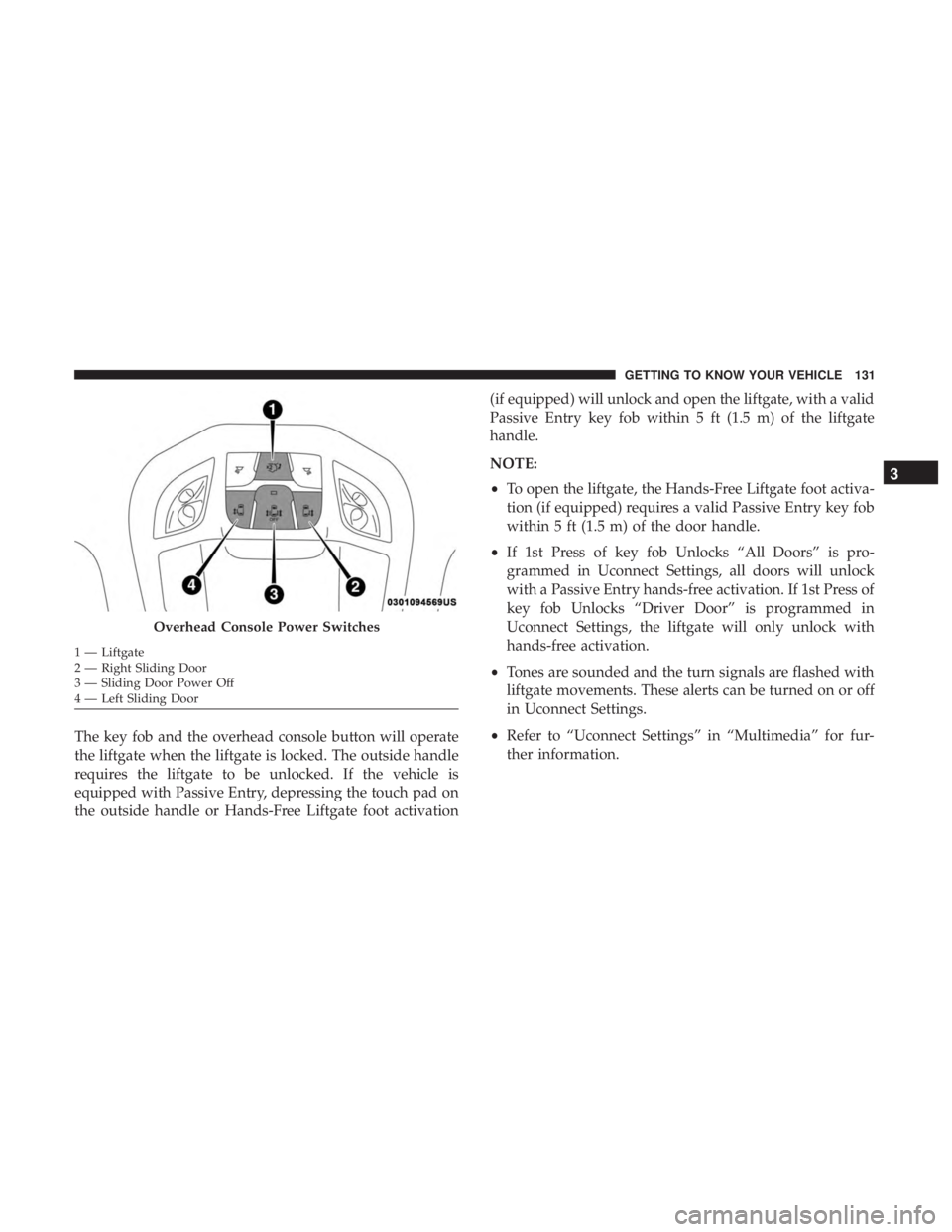
The key fob and the overhead console button will operate
the liftgate when the liftgate is locked. The outside handle
requires the liftgate to be unlocked. If the vehicle is
equipped with Passive Entry, depressing the touch pad on
the outside handle or Hands-Free Liftgate foot activation(if equipped) will unlock and open the liftgate, with a valid
Passive Entry key fob within 5 ft (1.5 m) of the liftgate
handle.
NOTE:
•
To open the liftgate, the Hands-Free Liftgate foot activa-
tion (if equipped) requires a valid Passive Entry key fob
within 5 ft (1.5 m) of the door handle.
• If 1st Press of key fob Unlocks “All Doors” is pro-
grammed in Uconnect Settings, all doors will unlock
with a Passive Entry hands-free activation. If 1st Press of
key fob Unlocks “Driver Door” is programmed in
Uconnect Settings, the liftgate will only unlock with
hands-free activation.
• Tones are sounded and the turn signals are flashed with
liftgate movements. These alerts can be turned on or off
in Uconnect Settings.
• Refer to “Uconnect Settings” in “Multimedia” for fur-
ther information.
Overhead Console Power Switches
1 — Liftgate
2 — Right Sliding Door
3 — Sliding Door Power Off
4 — Left Sliding Door
3
GETTING TO KNOW YOUR VEHICLE 131
Page 134 of 614
To Close The Liftgate
The liftgate can also be closed using the Rear Interior
Power Liftgate button (if equipped), located in the upper
left trim in the liftgate opening.
Lock The Vehicle
With a valid Passive Entry key fob within 5 ft (1.5 m) of the
liftgate, pushing the passive entry lock button located to
the right of the outside handle will lock the vehicle.Hands-Free Liftgate — If Equipped
To open the liftgate using hands-free activation, use a
straight in and out kicking motion under the vehicle
activation zone in the general location below the liftgate
door handle. Do not move your foot sideways or in a
sweeping motion or the sensors may not detect the motion.
When a valid kicking motion is completed, the liftgate will
chime, the hazard lights will flash and the liftgate will open
after approximately one second. This assumes all options
are enabled in the radio.
Rear Interior Power Liftgate Switch
Hands-Free Liftgate Activation Zone
132 GETTING TO KNOW YOUR VEHICLE
Page 135 of 614

NOTE:To open the Hands-Free Liftgate requires a valid
Passive Entry key fob within 5 ft (1.5 m) of the door handle.
If a valid Passive Entry key fob is not within 5 ft (1.5 m), the
liftgate will not respond to any kicks.
CAUTION!
The Hands-Free Liftgate feature may be turned on or
off in Uconnect Settings. Refer to “Uconnect Settings”
in “Multimedia” for further information. The Hands-
Free Liftgate feature should be turned off during
Jacking, Tire Changing, and Vehicle Service.
NOTE:
• The Hands-Free Liftgate will only operate when the
transmission is in Park.
• If anything obstructs the Hands-Free liftgate while it is
opening, the liftgate will automatically reverse to the
closed position, provided it meets sufficient resistance.
• There are pinch sensors attached to the side of the
liftgate opening. Light pressure anywhere along these
strips will cause the liftgate to return to the open
position. •
If the power liftgate encounters multiple obstructions
within the same cycle, the system will automatically
stop. If this occurs, the liftgate must be operated manu-
ally.
• The power liftgate will release, but not power open, in
temperatures below �12° F (�24° C). Be sure to remove
any buildup of snow or ice from the liftgate before
opening the liftgate.
• If the liftgate is left open for an extended period of time,
the liftgate may need to be closed manually to reset
power liftgate functionality.
WARNING!
• Driving with the liftgate open can allow poisonous
exhaust gases into your vehicle. You and your pas-
sengers could be injured by these fumes. Keep the
liftgate closed when you are operating the vehicle.
• If you are required to drive with the liftgate open,
make sure that all windows are closed, and the
climate control blower switch is set at high speed. Do
not use the recirculation mode.
3
GETTING TO KNOW YOUR VEHICLE 133
Page 146 of 614
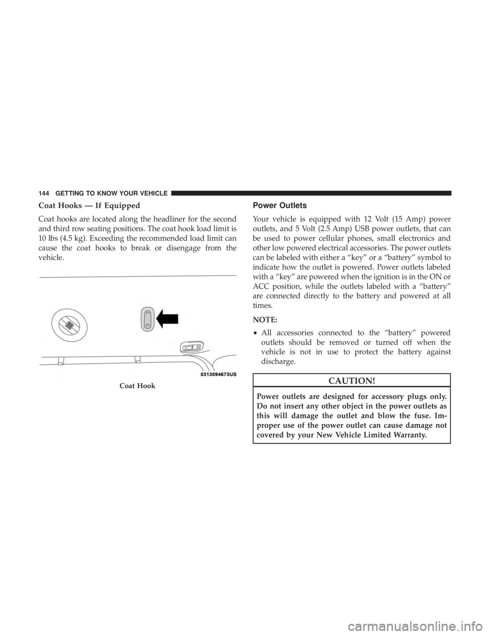
Coat Hooks — If Equipped
Coat hooks are located along the headliner for the second
and third row seating positions. The coat hook load limit is
10 lbs (4.5 kg). Exceeding the recommended load limit can
cause the coat hooks to break or disengage from the
vehicle.
Power Outlets
Your vehicle is equipped with 12 Volt (15 Amp) power
outlets, and 5 Volt (2.5 Amp) USB power outlets, that can
be used to power cellular phones, small electronics and
other low powered electrical accessories. The power outlets
can be labeled with either a “key” or a “battery” symbol to
indicate how the outlet is powered. Power outlets labeled
with a “key” are powered when the ignition is in the ON or
ACC position, while the outlets labeled with a “battery”
are connected directly to the battery and powered at all
times.
NOTE:
•All accessories connected to the “battery” powered
outlets should be removed or turned off when the
vehicle is not in use to protect the battery against
discharge.
CAUTION!
Power outlets are designed for accessory plugs only.
Do not insert any other object in the power outlets as
this will damage the outlet and blow the fuse. Im-
proper use of the power outlet can cause damage not
covered by your New Vehicle Limited Warranty.
Coat Hook
144 GETTING TO KNOW YOUR VEHICLE
Page 159 of 614
GETTING TO KNOW YOUR INSTRUMENT PANEL
CONTENTS
�INSTRUMENT CLUSTER ..................158
▫ Instrument Cluster Descriptions ............159
� INSTRUMENT CLUSTER DISPLAY ...........160
▫ Instrument Cluster Display Location
And Controls ......................... .160
▫ Oil Life Reset ........................ .161
▫ Fuel And Oil Refresh Mode ................162
▫ KeySense Cluster Messages — If Equipped .....163
▫ Instrument Cluster Display Menu Items .......164
▫ Battery Saver On/Battery Saver Mode Message —
Electrical Load Reduction Actions —
If Equipped ......................... .170�
WARNING LIGHTS AND MESSAGES .........172
▫ Red Warning Lights .....................173
▫ Yellow Warning Lights ...................177
▫ Yellow Indicator Lights ...................182
▫ Green Indicator Lights ...................182
▫ White Indicator Lights ...................183
▫ Blue Indicator Lights ....................184
� ONBOARD DIAGNOSTIC SYSTEM — OBD II . . .184
▫ Onboard Diagnostic System (OBD II)
Cybersecurity ........................ .184
� EMISSIONS INSPECTION AND MAINTENANCE
PROGRAMS .......................... .1854
Page 165 of 614
NOTE:Fuel Freshness is recalculated whenever fuel is
added to the vehicle’s fuel tank.
KeySense Cluster Messages — If Equipped
When the KeySense key is in use there will be:
•Continuous, dedicated telltale
• Unique Display Splash Screen
With KeySense in use there will be multiple associated
messages shown in the following table:
Setting Instrument Cluster Display Message
None – With vehicle ignition ON “KeySense in use. Max vehicle speed set to xx MPH/or km/h”
Max Vehicle Speed
• “Max speed reached. KeySense in use” supported by a chime
• “Approaching max speed xx MPH/km” supported by a chime
Start Up Fuel Alert message “Range to empty xxx miles or km”
Early Low Fuel Alert Message “Fuel Low”
ParkSense “Feature cannot be disabled. KeySense in use”
Blind Spot “Feature cannot be disabled. KeySense in use”
Forward Collision Warning “Feature cannot be disabled. KeySense in use”
4
GETTING TO KNOW YOUR INSTRUMENT PANEL 163
Page 172 of 614
Speed Warning — If Equipped
Push and release theupordown arrow button until Speed
Warning is highlighted in the instrument cluster display.
Push and release the OKbutton to enter speed warning.
Use the upordown arrow button to turn the speed
warning ON or OFF, then push and release the OKbutton
to confirm the selection. If the ON status is selected, use the
up ordown arrow button to set the desired speed, then
push the OKbutton to set the speed for the speed warning.
A speed warning telltale will illuminate in the instrument
cluster, with a number matching the set speed, with a pop
up message to inform the driver that the speed warning
has been set to the desired speed. Each time the set speed
is exceeded, a single chime will sound and a pop up
warning message will display. If the set speed is exceeded
more than 2 mph (3 km/h), a continuous chime will sound
for up to 10 seconds, or until the speed is no longer
exceeded. The telltale in the instrument cluster will also
change from white to yellow, and a pop up warning
message will pop up on the instrument cluster display.
NOTE: Speed Warning is unavailable while KeySense is in
use.
Battery Saver On/Battery Saver Mode Message —
Electrical Load Reduction Actions — If Equipped
The vehicle is equipped with an Intelligent Battery Sensor
(IBS) to perform additional monitoring of the 12 volt
electrical system and status of the 12 volt vehicle battery.
In cases when the IBS detects charging system failure, or
the 12 volt vehicle battery conditions are deteriorating,
electrical load reduction actions will take place to extend
the driving time and distance of the vehicle. This is done by
reducing power to or turning off non-essential 12 volt
electrical loads. Load reduction will be functional when the
vehicle propulsion system is active.
The vehicle may not be running depending on the HV
battery SOC or temperature. It will display a message if
there is a risk of battery depletion to the point where the
vehicle may stall due to lack of electrical supply, or will not
restart after the current drive cycle.
When 12 volt load reduction is activated, the message
“Battery Saver On” or “Battery Saver Mode” will appear in
the Instrument Cluster Display.
These messages indicate the 12 volt vehicle battery has a
low state of charge and continues to lose electrical charge at
a rate that the charging system cannot sustain.
170 GETTING TO KNOW YOUR INSTRUMENT PANEL