Page 361 of 614

Left Lane Departure — Both Lane Lines Detected
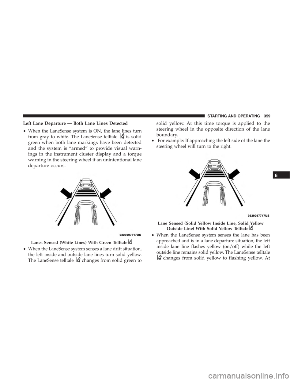
•When the LaneSense system is ON, the lane lines turn
from gray to white. The LaneSense telltale
is solid
green when both lane markings have been detected
and the system is “armed” to provide visual warn-
ings in the instrument cluster display and a torque
warning in the steering wheel if an unintentional lane
departure occurs.
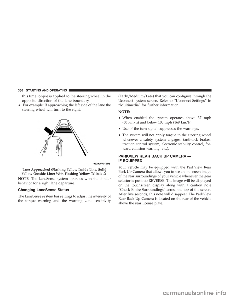
• When the LaneSense system senses a lane drift situation,
the left inside and outside lane lines turn solid yellow.
The LaneSense telltale
changes from solid green to solid yellow. At this time torque is applied to the
steering wheel in the opposite direction of the lane
boundary.
•
For example: If approaching the left side of the lane the
steering wheel will turn to the right.
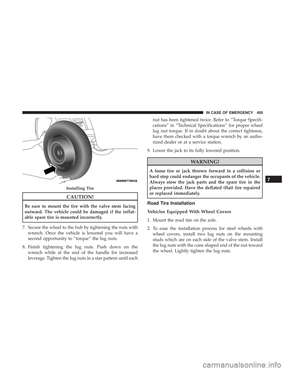
• When the LaneSense system senses the lane has been
approached and is in a lane departure situation, the left
inside lane line flashes yellow (on/off) while the left
outside line remains solid yellow. The LaneSense telltale
changes from solid yellow to flashing yellow. At
Lanes Sensed (White Lines) With Green Telltale
Lane Sensed (Solid Yellow Inside Line, Solid Yellow
Outside Line) With Solid Yellow Telltale
6
STARTING AND OPERATING 359
Page 362 of 614

this time torque is applied to the steering wheel in the
opposite direction of the lane boundary.
•For example: If approaching the left side of the lane the
steering wheel will turn to the right.
NOTE: The LaneSense system operates with the similar
behavior for a right lane departure.
Changing LaneSense Status
The LaneSense system has settings to adjust the intensity of
the torque warning and the warning zone sensitivity (Early/Medium/Late) that you can configure through the
Uconnect system screen. Refer to “Uconnect Settings” in
“Multimedia” for further information.
NOTE:
•
When enabled the system operates above 37 mph
(60 km/h) and below 105 mph (169 km/h).
• Use of the turn signal suppresses the warnings.
• The system will not apply torque to the steering wheel
whenever a safety system engages. (anti-lock brakes,
traction control system, electronic stability control, for-
ward collision warning, etc.).
PARKVIEW REAR BACK UP CAMERA —
IF EQUIPPED
Your vehicle may be equipped with the ParkView Rear
Back Up Camera that allows you to see an on-screen image
of the rear surroundings of your vehicle whenever the gear
selector is put into REVERSE. The image will be displayed
on the touchscreen display along with a caution note
“Check Entire Surroundings” across the top of the screen.
After five seconds, this note will disappear. The ParkView
Rear Back Up Camera is located on the rear of the vehicle
above the rear license plate.Lane Approached (Flashing Yellow Inside Line, Solid
Yellow Outside Line) With Flashing Yellow Telltale
360 STARTING AND OPERATING
Page 407 of 614

CAUTION!
Be sure to mount the tire with the valve stem facing
outward. The vehicle could be damaged if the inflat-
able spare tire is mounted incorrectly.
7. Secure the wheel to the hub by tightening the nuts with wrench. Once the vehicle is lowered you will have a
second opportunity to “torque” the lug nuts.
8. Finish tightening the lug nuts. Push down on the wrench while at the end of the handle for increased
leverage. Tighten the lug nuts in a star pattern until each nut has been tightened twice. Refer to “Torque Specifi-
cations” in “Technical Specifications” for proper wheel
lug nut torque. If in doubt about the correct tightness,
have them checked with a torque wrench by an autho-
rized dealer or at a service station.
9. Lower the jack to its fully lowered position.
WARNING!
A loose tire or jack thrown forward in a collision or
hard stop could endanger the occupants of the vehicle.
Always stow the jack parts and the spare tire in the
places provided. Have the deflated (flat) tire repaired
or replaced immediately.
Road Tire Installation
Vehicles Equipped With Wheel Covers
1. Mount the road tire on the axle.
2. To ease the installation process for steel wheels with wheel covers, install two lug nuts on the mounting
studs which are on each side of the valve stem. Install
the lug nuts with the cone shaped end of the nut toward
the wheel. Lightly tighten the lug nuts.
Installing Tire
7
IN CASE OF EMERGENCY 405
Page 408 of 614

3. Align the valve notch in the wheel cover with the valvestem on the wheel. Install the cover by hand, snapping
the cover over the two lug nuts. Do not use a hammer or
excessive force to install the cover.
4. Install the remaining lug nuts with the cone shaped end of the nut toward the wheel. Lightly tighten the lug
nuts.
WARNING!
To avoid the risk of forcing the vehicle off the jack, do
not tighten the wheel nuts fully until the vehicle has
been lowered. Failure to follow this warning may
result in serious injury.
5. Lower the vehicle to the ground by turning the jack handle counterclockwise.
6. Finish tightening the lug nuts. Push down on the wrench while at the end of the handle for increased
leverage. Tighten the lug nuts in a star pattern until each
nut has been tightened twice. Refer to “Torque Specifi-
cations” in “Technical Specifications” for proper wheel
lug nut torque. If in doubt about the correct tightness,
have them checked with a torque wrench by an autho-
rized dealer or at a service station.
7. After 25 miles (40 km) check the lug nut torque with a torque wrench to ensure that all lug nuts are properly
seated against the wheel.
Tire And Wheel Cover Or Center Cap
1 — Valve Stem 4 — Wheel Cover
2 — Valve Notch 5 — Mounting Stud
3 — Wheel Lug Nut 406 IN CASE OF EMERGENCY
Page 409 of 614

Vehicles Without Wheel Covers
1. Mount the road tire on the axle.
2. Install the remaining lug nuts with the cone shaped endof the nut toward the wheel. Lightly tighten the lug
nuts.
WARNING!
To avoid the risk of forcing the vehicle off the jack, do
not tighten the wheel nuts fully until the vehicle has
been lowered. Failure to follow this warning may
result in serious injury.
3. Lower the vehicle to the ground by turning the jack handle counterclockwise.
4. Finish tightening the lug nuts. Push down on the wrench while at the end of the handle for increased
leverage. Tighten the lug nuts in a star pattern until each
nut has been tightened twice. Refer to “Torque Specifi-
cations” in the “Technical Specifications” section for
proper wheel lug nut torque. If in doubt about the
correct tightness, have them checked with a torque
wrench by your authorized dealer or at a service station. 5. After 25 miles (40 km) check the lug nut torque with a
torque wrench to ensure that all lug nuts are properly
seated against the wheel.
TIRE SERVICE KIT — IF EQUIPPED
Your vehicle may be equipped with a Tire Service Kit.
Small punctures up to 1/4 inch (6 mm) in the tire tread can
be sealed with Tire Service Kit. Foreign objects (e.g., screws
or nails) should not be removed from the tire. Tire Service
Kit can be used in outside temperatures down to approxi-
mately -4°F (-20°C). This kit will provide a temporary tire
seal, allowing you to drive your vehicle up to 100 miles
(160 km) with a maximum speed of 50 mph (80 km/h).
Tire Service Kit Storage
The Tire Service Kit is secured with a strap and is stored in
the storage bin located behind the rear cargo trim panel.
7
IN CASE OF EMERGENCY 407
Page 493 of 614
TECHNICAL SPECIFICATIONS
CONTENTS
�IDENTIFICATION DATA ...................492
▫ Vehicle Identification Number .............492
� BRAKE SYSTEM ....................... .492
� WHEEL AND TIRE TORQUE SPECIFICATIONS . .492
▫ Torque Specifications ....................493
� FUEL REQUIREMENTS ...................494
▫ 3.6L Engine ......................... .494
▫ Reformulated Gasoline ..................494
▫ Materials Added To Fuel .................495
▫ Gasoline/Oxygenate Blends ...............495 ▫
Do Not Use E-85 In Non-Flex Fuel Vehicles . . . .496
▫ CNG And LP Fuel System Modifications ......496
▫ MMT In Gasoline ...................... .496
▫ Fuel System Cautions ....................496
▫ Carbon Monoxide Warnings ...............497
� FLUID CAPACITIES ..................... .498
� FLUIDS AND LUBRICANTS ................499
▫ Engine ............................. .499
▫ Chassis ............................ .501
9
Page 494 of 614

IDENTIFICATION DATA
Vehicle Identification Number
The Vehicle Identification Number (VIN) is on the left front
corner of the instrument panel and is visible from outside
of the vehicle through the windshield. This number also
appears stamped under the right front seat and printed on
the Automobile Information Disclosure Label affixed to a
window on your vehicle, the vehicle registration and title.
NOTE:It is illegal to remove or alter the VIN.
BRAKE SYSTEM
Your vehicle is equipped with dual hydraulic brake sys-
tems. If either of the two hydraulic systems loses normal
capability, the remaining system will still function. How-
ever, there will be some loss of overall braking effective-
ness. You may notice increased pedal travel during appli-
cation, greater pedal force required to slow or stop, and
potential activation of the Brake Warning Light.
In the event power assist is lost for any reason (i.e.,
repeated brake applications with the engine off) the brakes
will still function. However, the effort required to brake the
vehicle will be much greater than that required with the
power system operating.
WHEEL AND TIRE TORQUE SPECIFICATIONS
Proper lug nut/bolt torque is very important to ensure that
the wheel is properly mounted to the vehicle. Any time a
wheel has been removed and reinstalled on the vehicle, the
lug nuts/bolts should be torqued using a properly cali-
brated torque wrench using a high quality six sided (hex)
deep wall socket.
Vehicle Identification Number
492 TECHNICAL SPECIFICATIONS
Page 495 of 614
Torque Specifications
Lug Nut/BoltTorque **Lug Nut/Bolt
Size Lug Nut/Bolt
Socket Size
100 Ft-Lbs (135 N·m) M12 x 1.5 19 mm
**Use only your authorized dealer recommended lug nuts/
bolts and clean or remove any dirt or oil before tightening.
Inspect the wheel mounting surface prior to mounting the
tire and remove any corrosion or loose particles. Tighten the lug nuts/bolts in a star pattern until each
nut/bolt has been tightened twice. Ensure that the socket is
fully engaged on the lug nut/bolt (do not insert it half-
way).
After 25 miles (40 km) check the lug nut/bolt torque to be
sure that all the lug nuts/bolts are properly seated against
the wheel.
Wheel Mounting Surface
Torque Patterns
9
TECHNICAL SPECIFICATIONS 493