Page 275 of 492
prompt the driver to remain within the lane. When only a
single lane marking is detected, a haptic (torque) warning
will not be provided.
NOTE:When operating conditions have been met, the
LaneSense system will monitor if the driver ’s hands are on
the steering wheel and provides an audible warning to the
driver when the driver ’s hands are not detected on the
steering wheel. The system will cancel if the driver does
not return their hands to the wheel.
Turning LaneSense On Or Off
The default status of LaneSense is off.
The LaneSense button is located on the center stack below
the Uconnect display.
To turn the LaneSense system on, push the Lane-
Sense button (LED turns off). A “LaneSense On”
message is shown in the instrument cluster display.
To turn the LaneSense system off, push the LaneSense
button once (LED turns on).
NOTE: The LaneSense system will retain the last system
state, on or off, from the last ignition cycle when the
ignition is changed to the ON/RUN position.
LaneSense Warning Message
The LaneSense system will indicate the current lane drift
condition through the instrument cluster display.
Premium Instrument Cluster Display Screen — If
Equipped
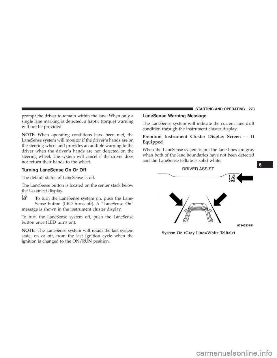
When the LaneSense system is on; the lane lines are gray
when both of the lane boundaries have not been detected
and the LaneSense telltale is solid white.
System On (Gray Lines/White Telltale)
6
STARTING AND OPERATING 273
Page 277 of 492
Left Lane Departure — Both Lanes Detected
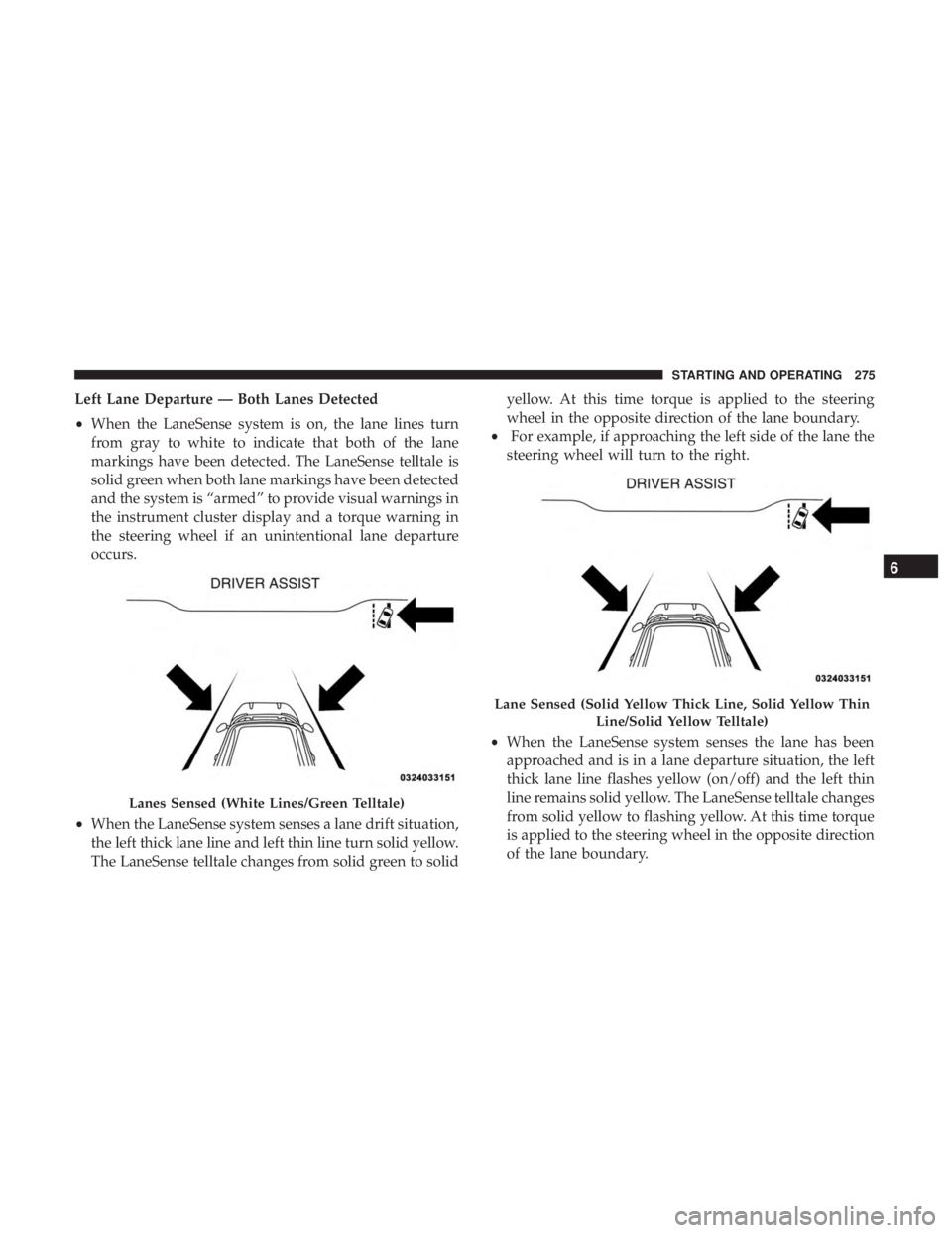
•When the LaneSense system is on, the lane lines turn
from gray to white to indicate that both of the lane
markings have been detected. The LaneSense telltale is
solid green when both lane markings have been detected
and the system is “armed” to provide visual warnings in
the instrument cluster display and a torque warning in
the steering wheel if an unintentional lane departure
occurs.
• When the LaneSense system senses a lane drift situation,
the left thick lane line and left thin line turn solid yellow.
The LaneSense telltale changes from solid green to solid yellow. At this time torque is applied to the steering
wheel in the opposite direction of the lane boundary.
• For example, if approaching the left side of the lane the
steering wheel will turn to the right.
• When the LaneSense system senses the lane has been
approached and is in a lane departure situation, the left
thick lane line flashes yellow (on/off) and the left thin
line remains solid yellow. The LaneSense telltale changes
from solid yellow to flashing yellow. At this time torque
is applied to the steering wheel in the opposite direction
of the lane boundary.
Lanes Sensed (White Lines/Green Telltale)
Lane Sensed (Solid Yellow Thick Line, Solid Yellow Thin
Line/Solid Yellow Telltale)
6
STARTING AND OPERATING 275
Page 278 of 492
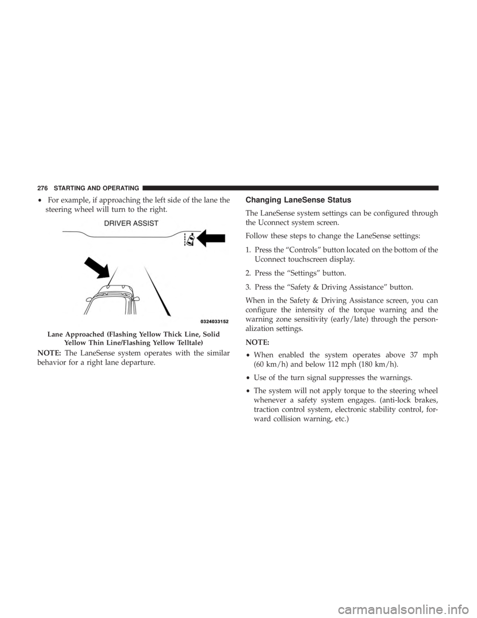
•For example, if approaching the left side of the lane the
steering wheel will turn to the right.
NOTE: The LaneSense system operates with the similar
behavior for a right lane departure.Changing LaneSense Status
The LaneSense system settings can be configured through
the Uconnect system screen.
Follow these steps to change the LaneSense settings:
1. Press the “Controls” button located on the bottom of the Uconnect touchscreen display.
2. Press the “Settings” button.
3. Press the “Safety & Driving Assistance” button.
When in the Safety & Driving Assistance screen, you can
configure the intensity of the torque warning and the
warning zone sensitivity (early/late) through the person-
alization settings.
NOTE:
• When enabled the system operates above 37 mph
(60 km/h) and below 112 mph (180 km/h).
• Use of the turn signal suppresses the warnings.
• The system will not apply torque to the steering wheel
whenever a safety system engages. (anti-lock brakes,
traction control system, electronic stability control, for-
ward collision warning, etc.)
Lane Approached (Flashing Yellow Thick Line, Solid
Yellow Thin Line/Flashing Yellow Telltale)
276 STARTING AND OPERATING
Page 323 of 492
CavityCartridge Fuse Mini-FuseDescription
68 –10 Amp Red Dual USB Power Outlet –
R/A Sense (Charger/300)
Rear Sunshade (Charger/
300) RR USB Timer
69 ––Fuse – Spare
70 ––Fuse – Spare
JACKING AND TIRE CHANGING
WARNING!
•Do not attempt to change a tire on the side of the
vehicle close to moving traffic. Pull far enough off
the road to avoid the danger of being hit when
operating the jack or changing the wheel.
• Being under a jacked-up vehicle is dangerous. The
vehicle could slip off the jack and fall on you. You
could be crushed. Never put any part of your body
under a vehicle that is on a jack. If you need to get
under a raised vehicle, take it to a service center
where it can be raised on a lift.
• Never start or run the engine while the vehicle is on
a jack.
(Continued)
WARNING! (Continued)
•The jack is designed to be used as a tool for changing
tires only. The jack should not be used to lift the
vehicle for service purposes. The vehicle should be
jacked on a firm level surface only. Avoid ice or
slippery areas.
Jack Location/Spare Tire Stowage
The jack and spare tire are both stowed under an access
cover in the trunk. Follow these steps to access the jack and
spare tire.
NOTE: The spare tire must be removed in order to access
the jack.
7
IN CASE OF EMERGENCY 321
Page 325 of 492
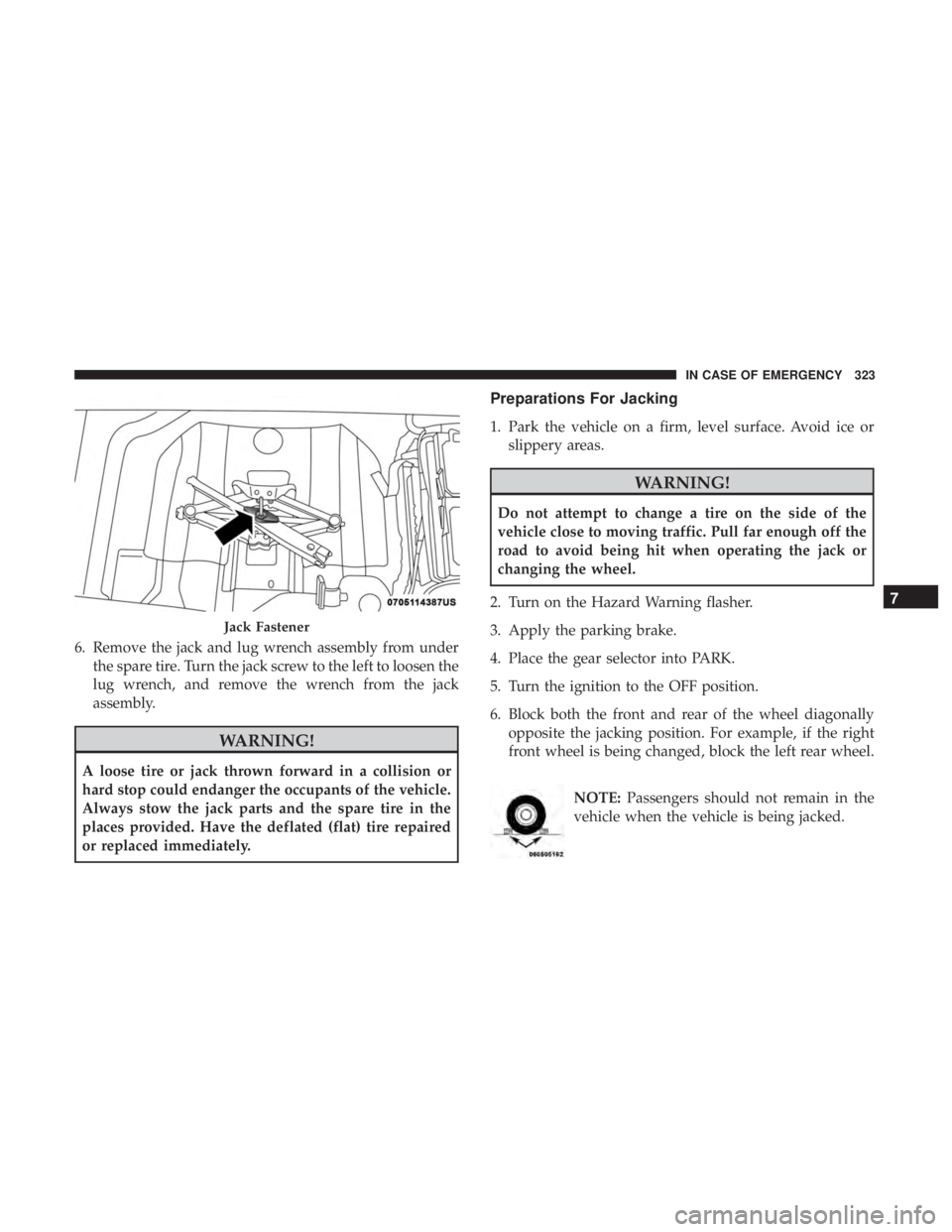
6. Remove the jack and lug wrench assembly from underthe spare tire. Turn the jack screw to the left to loosen the
lug wrench, and remove the wrench from the jack
assembly.
WARNING!
A loose tire or jack thrown forward in a collision or
hard stop could endanger the occupants of the vehicle.
Always stow the jack parts and the spare tire in the
places provided. Have the deflated (flat) tire repaired
or replaced immediately.
Preparations For Jacking
1. Park the vehicle on a firm, level surface. Avoid ice orslippery areas.
WARNING!
Do not attempt to change a tire on the side of the
vehicle close to moving traffic. Pull far enough off the
road to avoid being hit when operating the jack or
changing the wheel.
2. Turn on the Hazard Warning flasher.
3. Apply the parking brake.
4. Place the gear selector into PARK.
5. Turn the ignition to the OFF position.
6. Block both the front and rear of the wheel diagonally opposite the jacking position. For example, if the right
front wheel is being changed, block the left rear wheel.
NOTE:Passengers should not remain in the
vehicle when the vehicle is being jacked.
Jack Fastener
7
IN CASE OF EMERGENCY 323
Page 326 of 492
Jacking And Changing A Tire
WARNING!
Carefully follow these tire changing warnings to help
prevent personal injury or damage to your vehicle:
•Always park on a firm, level surface as far from the
edge of the roadway as possible before raising the
vehicle.
• Turn on the Hazard Warning flasher.
• Block the wheel diagonally opposite the wheel to be
raised.
• Apply the parking brake firmly and set the transmis-
sion in PARK.
• Do not let any passenger sit in the vehicle when it is
on a jack.
• Do not get under the vehicle when it is on a jack. If
you need to get under a raised vehicle, take it to a
service center where it can be raised on a lift.
• Only use the jack in the positions indicated and for
lifting this vehicle during a tire change.
• If working on or near a roadway, be extremely
careful of motor traffic.
CAUTION!
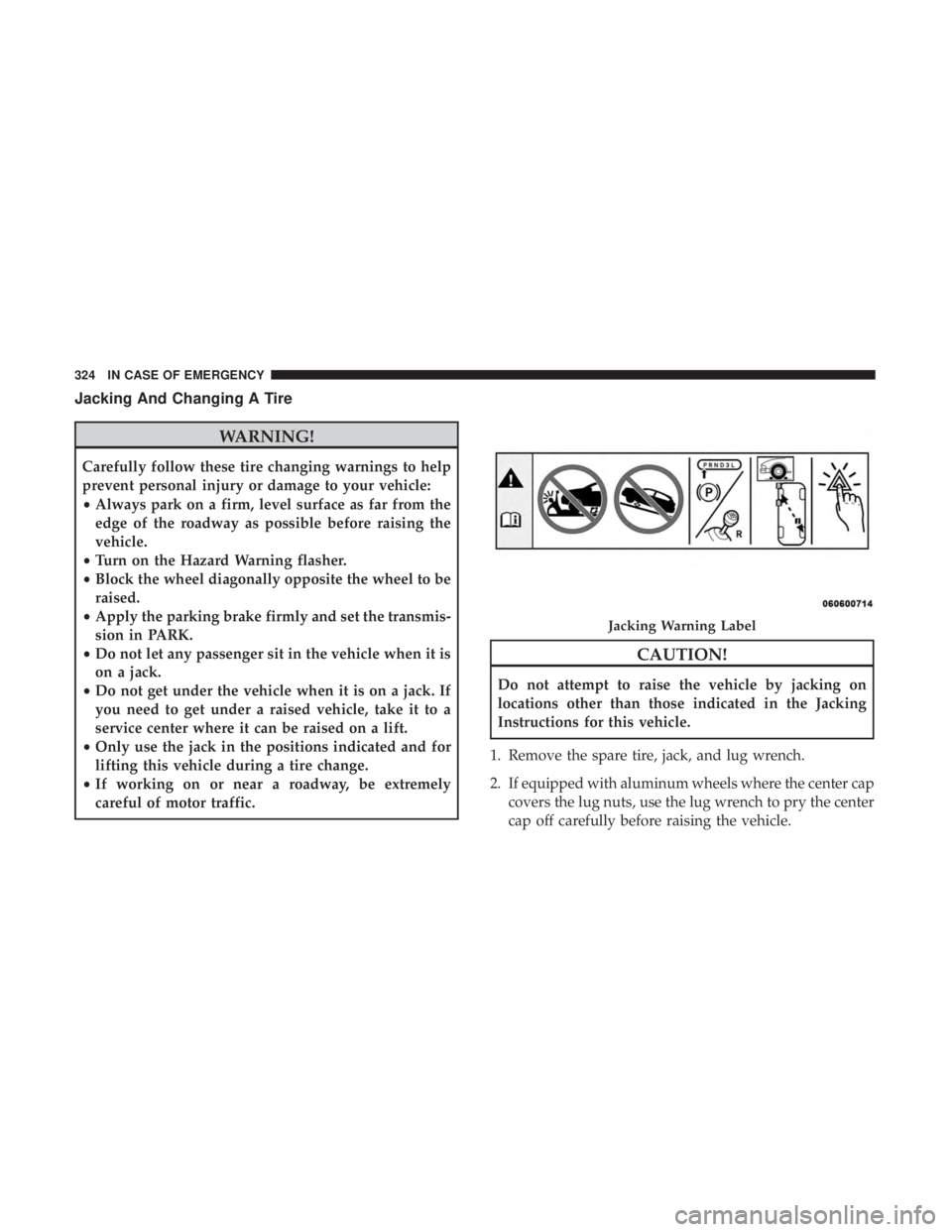
Do not attempt to raise the vehicle by jacking on
locations other than those indicated in the Jacking
Instructions for this vehicle.
1. Remove the spare tire, jack, and lug wrench.
2. If equipped with aluminum wheels where the center cap covers the lug nuts, use the lug wrench to pry the center
cap off carefully before raising the vehicle.
Jacking Warning Label
324 IN CASE OF EMERGENCY
Page 346 of 492
Mileage or time passed (whichever comes first)
20,000
30,000
40,000
50,000
60,000
70,000
80,000
90,000
100,000
110,000
120,000
130,000
140,000
150,000
Or Years: 2 3 4 5 6 7 8 9 10 11 12 13 14 15
Or Kilometers:
32,000
48,000
64,000
80,000
96,000
112,000
128,000
144,000
160,000
176,000
192,000
208,000
224,000
240,000
Change the transfer case fluid; if using your vehicle
for any of the following: police, taxi, fleet, off-road, or
frequent trailer towing. (All Wheel Drive Only). XX
Change the rear axle fluid and on models equipped
with All Wheel Drive (AWD) change the front axle
fluid if using your vehicle for any of the following: po-
lice, taxi, fleet, off-road, or frequent trailer towing. XX X
Inspect and replace PCV valve if necessary. X
** The spark plug change interval is mileage based only,
yearly intervals do not apply.
344 SERVICING AND MAINTENANCE
Page 372 of 492
fluid level checked. Operating the vehicle with an im-
proper fluid level can cause severe transmission damage.
CAUTION!
If a transmission fluid leak occurs, visit an authorized
dealer immediately. Severe transmission damage may
occur. An authorized dealer has the proper tools to
adjust the fluid level accurately.
Fluid And Filter Changes
Under normal operating conditions, the fluid installed at
the factory will provide satisfactory lubrication for the life
of the vehicle.
Routine fluid and filter changes are not required. However,
change the fluid and filter if the fluid becomes contami-
nated (with water, etc.), or if the transmission is disas-
sembled for any reason.
All Wheel Drive (AWD) — If Equipped
The all wheel drive system consists of a transfer case and
front differential. The exterior surface of these components
should be inspected for evidence of fluid leaks. Confirmed
leaks should be repaired as soon as possible.The transfer case fluid fill/inspection plug is located in the
middle of the rear housing. To inspect the transfer case
fluid level, remove the fill/inspection plug. The fluid level
should be even with the bottom of the hole. Use this plug
to add fluid as required.
The front differential fill plug is located on the outer cover
near the halfshaft attachment. To inspect the differential
fluid level, remove the fill plug. The fluid level should be
even with or slightly below the bottom of the hole.
Fluid Changes
Refer to “Scheduled Servicing” in “Servicing And Mainte-
nance” for the proper maintenance intervals.
Rear Axle
For normal service, periodic fluid level checks are not
required. When the vehicle is serviced for other reasons the
exterior surfaces of the axle assembly should be inspected.
If gear oil leakage is suspected inspect the fluid level. Refer
to “Fluids And Lubricants” in “Technical Specifications”
for further information.
370 SERVICING AND MAINTENANCE