2018 Alfa Romeo Giulietta air filter
[x] Cancel search: air filterPage 52 of 216

Warning lights on
panelWhat it means What to do
WATER IN DIESEL FILTER (Diesel versions)
The warning light switches on constantly when driving to indicate
the presence of water in the diesel filter.
19)
DPF CLEANING (particulate trap) in progress (diesel versions with
DPF only)
The warning light switches on when the ignition key is turned to
MAR, but it should switch off after a few seconds. The warning light
switches on constantly to indicate that the DPF system needs to
eliminate the trapped pollutants (particulate) through the
regeneration process.
The warning light does not come on during every DPF regeneration,
but only when driving conditions require that the driver is notified.
To turn off the warning light, keep the car in motion until the
regeneration process is over.
On average, the process lasts 15 minutes. Optimal conditions for
completing the process are achieved by travelling at 60 km/h with
engine speed above 2000 rpm.
When this warning light switches on, it does not indicate a vehicle
failure and thus it should not be taken to a workshop.
27)
iTPMS SYSTEM
The warning light switches on when the ignition key is turned to
MAR, but it should switch off after a few seconds.IMPORTANT Do not continue driving with one or
more flat tyres as handling may be compromised.
Stop the vehicle, avoiding sharp braking and
steering. Repair immediately using the dedicated
kit (see the "Replacing a wheel" paragraph in the
"In an emergency" section) and contact an Alfa
Romeo Dealership as soon as possible.
iTPMS failure/iTPMS temporarily deactivated
The warning light flashes for about 75 seconds and then stays on
constantly (see “Operating conditions” paragraph) to indicate that
the system is temporarily deactivated or faulty.
The system goes back to normal operation when the operating
conditions allow it. If this is not the case, carry out the Reset
procedure after restoring the normal operating conditions.If the malfunction warning persists, contact an
Alfa Romeo Dealership as soon as possible.
50
KNOWING THE INSTRUMENT PANEL
Page 127 of 216

Correct maintenance permits the performance of the car to be
maintained over time, as well as limited running costs and
safeguarding the efficiency of the safety systems.
This chapter explains how.
SERVICING AND MAINTENANCE
SCHEDULED SERVICING.........................126
SCHEDULED MAINTENANCE PLAN..................127
PERIODIC CHECKS............................134
DEMANDING USE OF THE CAR.....................134
CHECKING LEVELS ............................135
BATTERY RECHARGING .........................140
AIR CLEANER/POLLEN FILTER/DIESEL FILTER...........141
NOZZLES..................................141
HEADLIGHT WASHERS..........................142
BATTERY..................................142
LIFTING THE VEHICLE . .........................143
BODYWORK.................................144
INTERIOR..................................145
Page 131 of 216

Thousands of miles9 182736455463728190
Thousands of kilometres15 30 45 60 75 90 105 120 135 150
Years12345678910
Check and, if necessary, top up the Alfa TCT gearbox control
oil level (for versions/markets, where provided)(2)
Change engine oil and replace oil filter (1.4 Turbo Petrol and
1.4 Turbo MultiAir versions)(3) (o) (●)
Change engine oil and replace oil filter (1750 Turbo Petrol
versions)(4)
Replace spark plugs (1.4 Turbo Petrol and 1.4 Turbo MultiAir
versions)(5)
Replace spark plugs (1750 Turbo Petrol versions)
Replace accessory drive belt/s(6)
Replace the toothed timing drive belt(6)
(2) Check to be carried out every year for cars on the road in countries with particularly severe climates (cold countries).
(3) If the car's annual mileage is less than 10,000 km, the engine oil and filter must be replaced every year.
(o) Recommended operations
(●) Obligatory operations
(4) The actual interval for changing engine oil and replacing the engine oil filter depends on the vehicle usage conditions and is signalled by the warning light or message in
the instrument panel. In any cases, never exceed 1 year.
(5) For 1.4 Turbo Petrol and 1.4 Turbo MultiAir versions, to guarantee correct operation and prevent serious damage to the engine, it is essential to proceed as follows:
only use spark plugs specifically certified for these engines; all spark plugs should be of the same type and brand (see the “Engine” paragraph in the “Technical
specifications” section); strictly comply with the replacement intervals in the Service Schedule. It is advisable to contact an Alfa Romeo Dealership for spark plug
replacement.
(6) Areas that are not dusty: recommended maximum mileage 120,000 km. The belt must be replaced every 6 years, regardless of distance travelled. Dustyareas and/or
demanding use of the vehicle (cold climates, town use, long periods of idling): advised maximum mileage 60,000 km. Regardless of the mileage, the beltmust be
replaced every 4 years.
129
Page 132 of 216

Thousands of miles9 182736455463728190
Thousands of kilometres15 30 45 60 75 90 105 120 135 150
Years12345678910
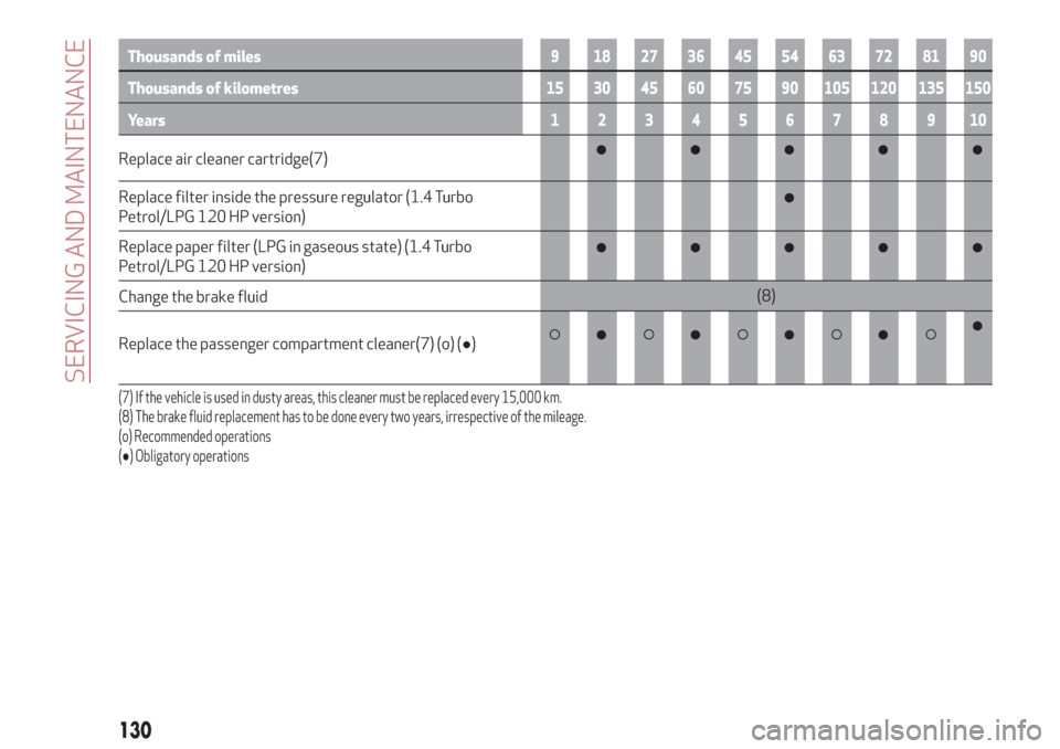
Replace air cleaner cartridge(7)
Replace filter inside the pressure regulator (1.4 Turbo
Petrol/LPG 120 HP version)
Replace paper filter (LPG in gaseous state) (1.4 Turbo
Petrol/LPG 120 HP version)
Change the brake fluid(8)
Replace the passenger compartment cleaner(7) (o) (●)
(7) If the vehicle is used in dusty areas, this cleaner must be replaced every 15,000 km.
(8) The brake fluid replacement has to be done every two years, irrespective of the mileage.
(o) Recommended operations
(●) Obligatory operations
130
SERVICING AND MAINTENANCE
Page 135 of 216

Thousands of miles12 24 36 48 60 72 84 96 108 120
Thousands of kilometres20 40 60 80 100 120 140 160 180 200
Years12345678910
Replace accessory drive belt/s(4)
Replace the toothed timing drive belt(4)
Replace fuel filter cartridge(5)
Replace air cleaner cartridge(6)
Change the brake fluid(7)
Replace the passenger compartment cleaner(6) (o) (●)
(4) Areas that are not dusty: recommended maximum mileage 120,000 km. The belt must be replaced every 6 years, regardless of distance travelled. Dustyareas and/or
demanding use of the vehicle (cold climates, town use, long periods of idling): advised maximum mileage 60,000 km. Regardless of the mileage, the beltmust be
replaced every 4 years.
(5) If the car runs on fuel with quality below the relevant European specification, this filter should be replaced every 20,000 km
(6) If the vehicle is used in dusty areas, this cleaner must be replaced every 20,000 km.
(7) The brake fluid replacement has to be done every two years, irrespective of the mileage.
(o) Recommended operations
(●) Obligatory operations
133
Page 136 of 216

PERIODIC CHECKS
Every 1,000 km or before long journeys,
check and, if necessary, top up the
following:
engine coolant, brake fluid and
windscreen washer fluid level;
tyre inflation pressure and condition;
operation of lighting system
(headlights, direction indicators, hazard
warning lights, etc.);
operation of screen wash/wipe system
and positioning/wear of windscreen/
rearscreen wiper blades
Check and top up, if required, the engine
oil level every 3,000 km.
IMPORTANT To find out the correct oil
quantity, always check using the dipstick.
Carry out the check with the vehicle
parked on level ground.
DEMANDING USE OF THE CAR
If the vehicle is used mainly under one of
the following conditions:
towing a trailer or caravan;
dusty roads;
short, repeated journeys (less than
7-8 km) at sub-zero outside
temperatures;
engine often idling or driving long
distances at low speeds or long periods
of inactivity;
the following checks must be carried out
more often than indicated in the
Scheduled Servicing Plan:
check front disc brake pad condition
and wear;
check cleanliness of bonnet and
luggage compartment locks, cleanliness
and lubrication of linkage;
visually inspect condition of: engine,
gearbox, transmission, pipes and hoses
(exhaust - fuel system - brakes) and
rubber elements (boots - sleeves - bushes
- etc.);
check battery charge and battery fluid
level (electrolyte);
visually inspect conditions of the
accessory drive belts;
check and, if necessary, change engine
oil and replace oil filter;
check and, if necessary, replace pollen
filter;
check and, if necessary, replace air
cleaner.
134
SERVICING AND MAINTENANCE
Page 142 of 216

132)The cooling system is pressurised. If
necessary, only replace the plug with
another original or the operation of the
system may be adversely affected. Do not
remove the reservoir plug when the engine is
hot: you risk scalding yourself.
133)Do not travel with the windscreen
washer fluid reservoir empty: the
windscreen washer is essential for
improving visibility. Repeated operation of
the system without fluid could damage or
cause rapid deterioration of some system
components.
134)Some commercial additives for
windscreen washer fluid are flammable. The
engine compartment contains hot
components which may start a fire.
135)Brake fluid is poisonous and highly
corrosive. In the event of accidental contact,
immediately wash the affected parts with
water and mild soap. Then rinse thoroughly.
Call a doctor immediately if swallowed.
136)The symbol
, on the brake fluid
container indicates if a brake fluid is
synthetic or mineral-based. Use of mineral
type fluids will damage the special rubber
seals of the braking system beyond repair.
IMPORTANT
3)Used engine oil and oil filters contain
substances which are harmful to the
environment. To change the oil and filters, we
advise you to contact an Alfa Romeo
Dealership.
4)Used transmission fluid contains
substances that are harmful to the
environment. You are advised to contact an
Alfa Romeo Dealership for oil changes.
BATTERY RECHARGING
IMPORTANT The battery recharging
procedure is given as information only. To
carry out this operation contact an Alfa
Romeo Dealership.
IMPORTANT After turning the ignition
key to STOP and having closed the
driver's side door, wait at least one
minute before disconnecting and then
reconnecting the electrical supply to the
battery.
Charging should be slow at a low ampere
rating for approximately 24 hours.
Charging for a longer time may damage
the battery.
IMPORTANT The cables of the electrical
system must be correctly reconnected to
the battery, i.e. the positive cable (+) to
the positive terminal and the negative
cable (–) to the negative terminal. The
battery terminals are marked with the
positive (+) and negative (–) symbols, and
are shown on the battery cover. The
battery terminals must also be
corrosion-free and firmly secured to the
terminals. If a "quick-type" battery
charger is used with the battery fitted on
the vehicle, before connecting it
disconnect both cables of the battery
itself. Do not use a "quick-type" battery
charger to provide the starting voltage.The cables of the electrical system must
be correctly reconnected to the battery,
i.e. the positive cable (+) to the positive
terminal and the negative cable (–) to the
negative terminal. The battery terminals
are marked with the positive (+) and
negative (–) symbols, and are shown on
the battery cover. The battery terminals
must also be corrosion-free and firmly
secured to the terminals.
VERSIONS WITHOUT START&STOP
SYSTEM
(for versions/markets, where provided)
To recharge, proceed as follows:
disconnect the terminal from the
negative battery pole;
connect the charger cables to the
battery terminals, observing the polarity;
turn on the charger;
when it is recharged, turn the charger
off before disconnecting it from the
battery;
reconnect the terminal to the negative
battery pole.
VERSIONS WITH START&STOP
SYSTEM
(for versions/markets, where provided)
To recharge, proceed as follows:
disconnect the connector 1
fig. 122(pressing the button 2) from the
sensor 3 monitoring the battery
conditions, on the negative pole (–) 4 of
the battery;
140
SERVICING AND MAINTENANCE
Page 143 of 216

connect the positive cable (+) of the
battery charger to the positive battery
terminal 5 and the negative cable (–) to
sensor terminal 4 as shown in fig. 123;
turn on the battery charger. At the end
of the charging process, switch the
battery charger off;
after having disconnected the
charging device, reconnect connector
1 to the sensor 3 as shown.
AIR CLEANER/POLLEN
FILTER/DIESEL FILTER
For filter replacement, contact an Alfa
Romeo Dealership.
NOZZLES
137)
46)
Windscreen washer
The window washer nozzles are fixed. If
there is no jet of fluid, first check that
there is some fluid in the reservoir (see
paragraph "Checking fluid levels"). Then
check that the nozzle holes are not
clogged, if necessary use a needle.
WARNING In versions with sun roof,
make sure that the roof is closed before
operating the windscreen washer
nozzles.
Rear window washer
The nozzle holder is on the rear window.
The rear window washer jets are fixed.
122A0K0530AC
123A0K0530BC
141