2018.5 OPEL AMPERA E tow
[x] Cancel search: towPage 191 of 273

Driving and operating189Select the relevant setting in Settings
I Vehicle settings in the Info Display.
Info Display 3 85.
Vehicle personalisation 3 91.
Fault
The system may not operate properly
when:
● Ice, snow, mud, or anything else covers the sensors.
● The vehicle had a rear end accident.
● There are extreme temperature changes.
Traffic sign assistant
Functionality
Traffic sign assistant detects
designated traffic signs via a front
camera and displays them in the
Driver Information Centre.
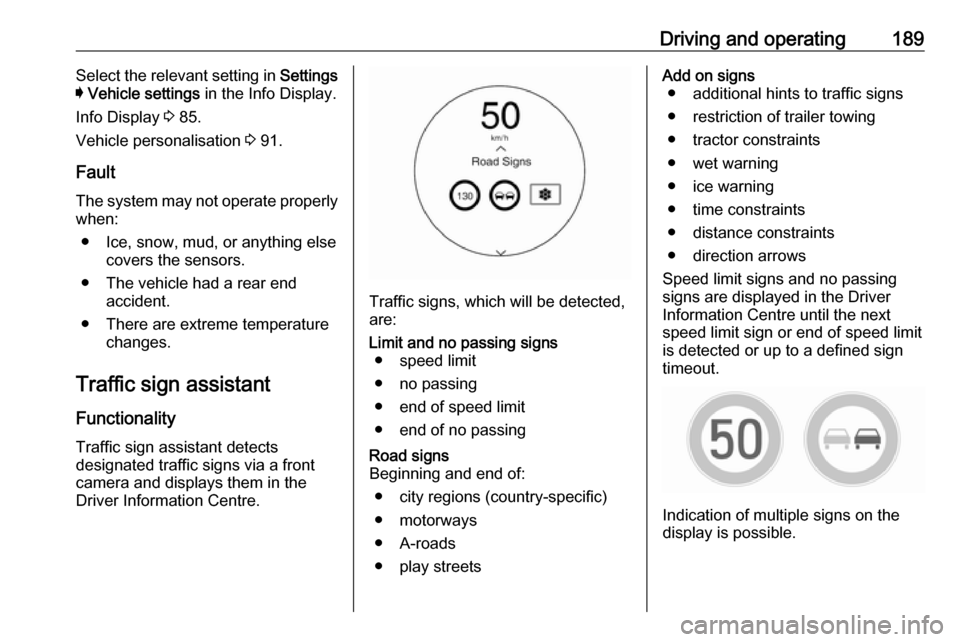
Traffic signs, which will be detected,
are:
Limit and no passing signs ● speed limit
● no passing
● end of speed limit
● end of no passingRoad signs
Beginning and end of:
● city regions (country-specific)● motorways
● A-roads
● play streetsAdd on signs ● additional hints to traffic signs
● restriction of trailer towing
● tractor constraints
● wet warning
● ice warning
● time constraints
● distance constraints
● direction arrows
Speed limit signs and no passing
signs are displayed in the Driver
Information Centre until the next
speed limit sign or end of speed limit
is detected or up to a defined sign
timeout.
Indication of multiple signs on the
display is possible.
Page 211 of 273

Driving and operating209Electrical requirementsCaution
Do not use portable or stationary
backup generating equipment to charge the vehicle. This may
cause damage to the vehicle's
charging system. Only charge the
vehicle from utility supplied power.
Charge limit selection 3 197.
Reduced limit mode allows a non-
dedicated circuit to be used but
increases the charging time.
This vehicle is capable of being
charged with standard vehicle
charging equipment complying with
one or more of the following
standards:
● SAE J1772
● SAE J2847–2
● IEC 61851-1
● IEC 61851-22
● IEC 61851-23
● IEC 61851-24
● IEC 62196-1
● IEC 62196-2
● IEC 62196-3
● ISO 15118
Ensure that all local electrical code / standards are being met for a 10 A
continuous load. Always follow the
charging equipment installation
instructions. Contact a workshop for
more information.9 Warning
If the capacity of the electrical
circuit or AC socket is not known,
only use the lowest charge level
until the circuit capacity has been
inspected by a qualified
electrician. Using a charge level
that exceeds either the electrical
circuit or the AC outlet capacity
may start a fire or damage the
electrical circuit.
Towing
General information
The vehicle is neither designed nor
intended to tow a trailer or another vehicle.
Page 212 of 273

210Vehicle careVehicle careGeneral Information...................210
Accessories and vehicle modifications .......................... 210
Lifting the vehicle .....................211
Vehicle storage ........................211
End-of-life vehicle recovery .....212
Vehicle checks ........................... 212
Performing work ......................212
Bonnet ..................................... 213
Cooling system ........................214
Washer fluid ............................ 216
Brakes ..................................... 216
Brake fluid ............................... 216
Vehicle battery ......................... 217
Wiper blade replacement ........219
Headlight aiming ......................219
Bulb replacement .......................220
Halogen bulbs ......................... 220
Xenon headlights .....................220
Front turn lights .......................220
Tail lights ................................. 221
Side turn lights ......................... 221
Number plate light ...................222Electrical system ........................223
High voltage devices and wiring ...................................... 223
Electrical system overload .......223
Fuses ....................................... 223
Engine compartment fuse box . 225
Instrument panel fuse box .......228
Vehicle tools .............................. 231
Tools ........................................ 231
Wheels and tyres .......................231
Tyres ....................................... 231
Winter tyres ............................. 232
Tyre designations ....................232
Tyre pressure .......................... 232
Tyre pressure monitoring system .................................... 233
Tread depth ............................. 235
Changing tyre and wheel size . 236
Wheel covers ........................... 236
Tyre chains .............................. 237
Tyre repair kit .......................... 237
Jump starting ............................. 240
Towing ....................................... 242
Towing the vehicle ...................242
Towing another vehicle ...........243
Appearance care .......................244
Exterior care ............................ 244
Interior care ............................. 245General Information
Accessories and vehiclemodifications
We recommend the use of genuine
parts and accessories and factory
approved parts specific for your
vehicle type. We cannot assess or
guarantee reliability of other products - even if they have a regulatory or
otherwise granted approval.
Any modification, conversion or other
changes made to standard vehicle
specifications (including, without
limitation, software modifications,
modifications of the electronic control units) may invalidate the warranty
offered by Opel. Furthermore, such
changes may affect driver assistance
systems and energy consumption.
They may also invalidate the vehicle
operating permit.Caution
When transporting the vehicle on
a train or on a recovery vehicle, the
mud flaps might be damaged.
Page 233 of 273

Vehicle care231Vehicle tools
Tools
Open the floor cover of the load
compartment 3 60.
The towing eye and a screwdriver are
located under a cover in the load
compartment.
Tyre repair kit 3 237.
Wheels and tyres
Tyre condition, wheel condition Drive over edges slowly and at right
angles if possible. Driving over sharp
edges can cause tyre and wheel
damage. Do not trap tyres on the kerb when parking.
Regularly check the wheels for
damage. Seek the assistance of a
workshop in the event of damage or
unusual wear.
Tyres
Self-sealing tyres This vehicle may have self-sealing
tyres. These tyres have a material
inside that can seal punctures up to
6 mm in the tread area.
The tyre may lose air pressure if the
sidewall is damaged or the tread
puncture is too large. If the Tyre
pressure monitoring system indicates the tyre pressure is low, inspect the
tyre for damage and inflate it to the
recommended pressure. If the tyre isunable to maintain the recommended
pressure, seek the assistance of a
workshop.Caution
Do not drive with a deflated self-
sealing tyre as this could damage
the tyre. Make sure the tyre is
inflated to the recommended
pressure or have it immediately
repaired or replaced.
When tyre replacement is needed,
replace with a self-sealing tyre,
because the vehicle does not come
with a spare tyre or tyre changing
equipment.
Directional tyres
If possible, fit directional tyres such
that they roll in the direction of travel.
The rolling direction is indicated by a
symbol (e.g. an arrow) on the
sidewall.
Page 241 of 273

Vehicle care239
Set the rocker switch on the
compressor to I. The tyre is filled
with sealant.
10. The compressor pressure gauge briefly indicates up to 6 bar whilstthe sealant bottle is emptying
(approx. 30 seconds). Then the
pressure starts to drop.
11. All of the sealant is pumped into the tyre. Then the tyre is inflated.
12. The prescribed tyre pressure should be obtained within
10 minutes.
Tyre pressure 3 254.
When the correct pressure is
obtained, switch off the
compressor.If the prescribed tyre pressure is
not obtained within 10 minutes,
remove the tyre repair kit. Move
the vehicle one tyre rotation.
Reattach the tyre repair kit and
continue the filling procedure for
10 minutes. If the prescribed tyre
pressure is still not obtained, the
tyre is too badly damaged. Seek
the assistance of a workshop.
Drain excess tyre pressure with
the button over the pressure indicator.
Do not run the compressor for
longer than 10 minutes.
13. Detach the tyre repair kit. Push catch on bracket to remove
sealant bottle from bracket. Screw
the tyre inflation hose to the free
connection of the sealant bottle.
This prevents sealant from
escaping. Stow tyre repair kit in
load compartment.
14. Remove any excess sealant using a cloth.
15. Take the label indicating maximum permitted speed from
the sealant bottle and affix in the
driver's field of view.
16. Continue driving immediately so that sealant is evenly distributed
in the tyre. After driving approx.
10 km (but no more than
10 minutes), stop and check tyre
pressure. Screw compressor air
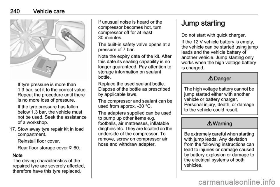
hose directly onto tyre valve and
compressor when doing this.
Page 242 of 273

240Vehicle care
If tyre pressure is more than
1.3 bar , set it to the correct value.
Repeat the procedure until there
is no more loss of pressure.
If the tyre pressure has fallen
below 1.3 bar, the vehicle must
not be used. Seek the assistance
of a workshop.
17. Stow away tyre repair kit in load compartment.
Reinstall floor cover.
Rear floor storage cover 3 60.
Note
The driving characteristics of the
repaired tyre are severely affected,
therefore have this tyre replaced.
If unusual noise is heard or the
compressor becomes hot, turn
compressor off for at least
30 minutes.
The built-in safety valve opens at a
pressure of 7 bar.
Note the expiry date of the kit. After
this date its sealing capability is no
longer guaranteed. Pay attention to
storage information on sealant
bottle.
Replace the used sealant bottle. Dispose of the bottle as prescribed
by applicable laws.
The compressor and sealant can be used from approx. -30 °C.
The adapters supplied can be used
to pump up other items e.g.
footballs, air mattresses, inflatable
dinghies etc. They are located on the
underside of the compressor. To
remove, screw on compressor air hose and withdraw adapter.Jump starting
Do not start with quick charger.
If the 12 V vehicle battery is empty,
the vehicle can be started using jump leads and the vehicle battery of
another vehicle. Jump starting only
works when the high voltage battery
is charged.9 Danger
The high voltage battery cannot be
jump started either with another
vehicle or battery charger.
Personal injury, death, or damage
to the vehicle could result.
9 Warning
Be extremely careful when starting
with jump leads. Any deviation
from the following instructions can
lead to injuries or damage caused
by battery explosion or damage to the electrical systems of both
vehicles.
Page 244 of 273

242Vehicle careJump starting the vehicle
Lead connection order:1. Connect the red lead to the positive terminal of the booster
vehicle battery.
2. Connect the other end of the red lead to the positive terminal of
your vehicle.
3. Connect the black lead to the negative terminal of the booster
vehicle battery.
4. Connect the other end of the black
lead to the negative battery
terminal (stud).
Route the leads so that they cannot
catch on rotating parts in the engine
compartment.
To start the vehicle: 1. Start the engine of the vehicle providing the jump.
2. After 5 minutes, press POWERm
to switch on the vehicle.
After the instrument cluster
initialises, the vehicle will use
power from the high voltage
battery to charge the 12 V vehicle
battery.
3. Switch on electrical consumers (e.g. headlights, heated rear
window) of the vehicle receiving
the jump start.
4. Reverse above sequence exactly when removing leads.Towing
Towing the vehicleCaution
Incorrect towing of a disabled
vehicle may cause damage to the
vehicle. The disabled vehicle
should only be towed on a flatbed
car carrier.
Ensure the vehicle is only towed
by well trained technicians.
Wrap a cloth around the tip of a slot
screwdriver to prevent paint damage. Insert the screwdriver in the slot at the
Page 245 of 273

Vehicle care243short edge of the cap. Release the
cap by carefully moving the
screwdriver sidewards.
The towing eye is stowed with the vehicle tools 3 231.
Screw in the towing eye anticlockwise
as far as it will go until it stops in a
horizontal position.
Attach a tow rope – or better still a tow
rod – to the towing eye.
The towing eye must only be used for
towing and not for recovering the
vehicle.
Switch on the vehicle to release
steering wheel lock and to permit
operation of brake lights, horn and
windscreen wiper.Caution
Deactivate the driver assistance
systems like active emergency
braking 3 170, otherwise the
vehicle may automatically brake during towing.
Shift the selector lever of the electric
drive unit into N.
Release the electric parking brake.
Caution
Drive slowly. Do not drive jerkily.
Excessive tractive force can
damage the vehicle.
When the vehicle is not running, considerably more force is needed to
brake and steer.
To prevent the entry of exhaust gases from the towing vehicle, switch on the
air recirculation and close the
windows.
Seek the assistance of a workshop.
After towing, unscrew the towing eye.
Insert cap at the bottom and close.
Towing another vehicle The vehicle is neither designed nor
intended to tow a trailer or another
vehicle.