Page 49 of 154

4-21
4
11. Connect the air intake duct to the throttle
body, and then tighten the clamp screw at the
throttle body side. NOTICE: Make sure that
the air intake duct is properly connected to
the throttle body, and that the clamp
screw is tightened securely.
[ECB00962]
12. Connect the coupler.
13. Connect the air filter case to the air intake duct, place the air filter case in the original po-
sition, and then tighten the clamp screw at
the air filter case side. NOTICE: Make sure
that the air intake duct is properly con-
nected to the air filter case, and that the
clamp screw is tightened securely.
[ECB00972]
14. Install the air filter case bolts, and then tighten them to the specified torque. 15. Install the air filter case holding plate by in-
stalling the bolts and collars, and then tighten
the bolts to the specified torque.
16. Install the blow-by gas chamber by installing the bolt, tighten the bolt to the specified
torque, and then install the clip to the hose
holder.
17. Install the cowling.
Rebound damping force
Turn the rebound damping force adjusting screw
in direction (a) to increase the rebound damping
force and thereby harden the damping, and in di-
rection (b) to decrease the rebound damping force
and thereby soften the damping.
Tightening torque:
Locknut:30 N·m (3.0 kgf·m, 22 lb·ft)
Tightening torque: Air filter case bolt:7 N·m (0.7 kgf·m, 5.1 lb·ft)
Tightening torque: Air filter case holding plate bolt:7 N·m (0.7 kgf·m, 5.1 lb·ft)
Tightening torque: Blow-by gas chamber bolt:7 N·m (0.7 kgf·m, 5.1 lb·ft)
UBW260E0.book Page 21 Thursday, May 12, 2016 2:28 PM
Page 50 of 154
4-22
4Compression damping force
Remove the seat to make this adjustment. (See
page 4-10.) 
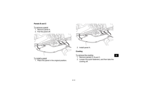
If the adjustment is difficult, it may be
necessary to remove panels A and C. (See page
8-10.)
Compression damping force (for fast compres-
sion damping)To increase the compression damping force and
thereby harden the compression damping, turn
the compression damping force adjusting bolt in
direction (a). To decrease the compression damp-
ing force and thereby soften the compression
damping, turn the adjusting bolt in direction (b).
1. Rebound damping force adjusting screwRebound damping setting:
Minimum (soft):30 click(s) in direction (b)*
Standard: 15 click(s) in direction (b)*
Maximum (hard): 1 click(s) in direction (b)*
* With the adjusting screw fully turned in di- rection (a)
1
(a)
(b)
1. Compression damping force adjusting bolt (for fast
compression damping)
(a)
(b)
1
UBW260E0.book Page 22 Thursday, May 12, 2016 2:28 PM
Page 51 of 154
4-23
4
Compression damping force (for slow compres-
sion damping)To increase the compression damping force and
thereby harden the compression damping, turn
the compression damping force adjusting screw
in direction (a). To decrease the compression
damping force and thereby soften the compres-
sion damping, turn the adjusting screw in direction
(b). Compression damping setting (for fast com-
pression damping):
Minimum (soft):2 turn(s) out from the fully turned in posi-
tion
Standard: 1 turn(s) out from the fully turned in posi-
tion
Maximum (hard): Adjusting bolt fully turned in
1. Compression damping force adjusting screw (for slow compression damping)Compression damping setting (for slow com-
pression damping):
Minimum (soft):20 click(s) in direction (b)*
Standard: 8 click(s) in direction (b)*
Maximum (hard): 1 click(s) in direction (b)*
* With the adjusting screw fully turned in di- rection (a)
(a)
(b)
1
UBW260E0.book Page 23 Thursday, May 12, 2016 2:28 PM
Page 52 of 154
4-24
4
WARNING
EWB00431This shock absorber assembly contains highly
pressurized nitrogen gas. Read and under-
stand the following information before han-
dling the shock absorber assembly.
Do not tamper with or attempt to open the
cylinder assembly.
Do not subject the shock absorber assembly
to an open flame or other high heat source.
This may cause the unit to explode due to ex-
cessive gas pressure.
Do not deform or damage the cylinder in any
way. Cylinder damage will result in poor
damping performance.
Do not dispose of a damaged or worn out
shock absorber assembly yourself. Take the
shock absorber assembly to a Yamaha deal-
er for any service. EBU29403Handlebar positionThe handlebar can be adjusted to one of two po-
sitions to suit the rider’s preference. Have a
Yamaha dealer adjust the position of the handle- bar.
1. Handlebar
1
UBW260E0.book Page 24 Thursday, May 12, 2016 2:28 PM
Page 53 of 154

5-1
5
EBU19203
PRE-OPERATION CHECKS
EBU19226Inspect your vehicle each time you use it to make sure the vehicle is in safe operating condition. Always
follow the inspection and maintenance procedures and schedules described in the Owner’s Manual.
WARNING
EWB00482Failure to inspect or maintain the vehicle properly increases the possibility of an accident or equip-
ment damage. Do not operate the vehicle if you find any problem. If a problem cannot be corrected
by the procedures provided in this manual, have the vehicle inspected by a Yamaha dealer. Before using this vehicle, check the following points:
ITEMROUTINE PAGE
Fuel • Check fuel level in fuel tank,
and add recommended fuel if neces-
sary.
• Check fuel line for leakage. Correct if necessary. 4-9, 5-4
Engine oil • Check oil level in engine oil tank, and add recommended oil to
specified level if necessary.
• Check ATV for oil leakage. Correct if necessary. 5-4, 8-14
Coolant • Check coolant level in reservoir, and add recommended coolant to
specified level if necessary.
• Check cooling system for leakage. Correct if necessary. 5-4, 8-20
UBW260E0.book Page 1 Thursday, May 12, 2016 2:28 PM
Page 54 of 154

5-2
5
Front brake• Check operation. If soft or spongy, have Yamaha dealer bleed hy-
draulic system.
• Check brake pads for wear, and replace if necessary.
• Check brake fluid level in reservoir, and add specified brake fluid to specified level if necessary.
• Check hydraulic system for leakage. Correct if necessary. 5-4, 8-28, 8-29, 8-31
Rear brake • Check operation. If soft or spongy, have Yamaha dealer bleed hy-
draulic system.
• Check brake pads for wear, and replace if necessary.
• Check brake fluid level in reservoir, and add specified brake fluid to specified level if necessary.
• Check hydraulic system for leakage. Correct if necessary. 5-4, 8-28, 8-29, 8-31
Clutch • Check operation, and correct if necessary.
• Lubricate cable if necessary.
• Check lever free play, and adjust if necessary. 8-33
Throttle lever • Make sure that operation is smooth. Lubricate cable and lever
housing if necessary.
• Check lever free play, and adjust if necessary. 5-5, 8-27
Control cables • Make sure that operation is smooth. Lubricate if necessary. 8-37
Drive chain • Check chain slack, and adjust if necessary.
• Check chain condition. Lubricate if necessary. 5-5, 8-35, 8-37
Wheels and tires • Check wheel condition, and replace if damaged.
• Check tire condition and tread depth. Replace if necessary.
• Check air pressure. Correct if necessary. 5-5
Shift pedal • Make sure that operation is smooth.
• Correct if necessary.
8-39
Brake pedal • Make sure that operation is smooth. Lubricate pedal pivoting point
if necessary. 8-39
ITEM ROUTINE PAGEUBW260E0.book Page 2 Thursday, May 12, 2016 2:28 PM
Page 55 of 154
5-3
5
Brake and clutch levers• Make sure that operation is smooth. Lubricate lever pivoting points
if necessary. 8-38
Chassis fasteners • Make sure that all nuts, bolts and screws are properly tightened. 5-7
Instruments, lights and
switches • Check operation, and correct if necessary. 5-8
ITEM ROUTINE PAGE
UBW260E0.book Page 3 Thursday, May 12, 2016 2:28 PM
Page 56 of 154

5-4
5
EBU19542FuelMake sure that there is sufficient fuel in the tank.
(See page 4-9.)EBU19561Engine oilMake sure that the engine oil is at the specified
level. Add oil as necessary. (See page 8-14.)EBU19632CoolantMake sure that the coolant is at the specified level.
Add coolant as necessary. (See page 8-20.)TIPThe coolant level must be checked on a cold en-
gine since the level varies with engine tempera-
ture. EBU19713Front and rear brakesBrake lever and brake pedal
Check that there is no free play in the brake le-
ver. If there is free play, have a Yamaha dealer
check the brake system.
Check for correct brake pedal height. (See page
8-31.) If the pedal height is incorrect, have a
Yamaha dealer adjust it.
Check the operation of the lever and pedal.
They should move smoothly and there should
be a firm feeling when the brakes are applied. If
not, have a Yamaha dealer check the brake sys-
tem.
Brake fluid level
Check the brake fluid level. Add fluid if necessary.
(See page 8-29.)
Brake fluid leakage
Check to see if any brake fluid is leaking out of the
pipe joints or brake fluid reservoirs. Apply the
brakes firmly for one minute. If there is any leak-
age, have a Yamaha dealer check the brake sys-
tem. Specified brake fluid:
DOT 4UBW260E0.book Page 4 Thursday, May 12, 2016 2:28 PM