2017 YAMAHA WR 250F checking oil
[x] Cancel search: checking oilPage 228 of 432

CLUTCH......................................................................................................... 6-42
REMOVING THE CLUTCH ...................................................................... 6-45
CHECKING THE FRICTION PLATES...................................................... 6-45
CHECKING THE CLUTCH PLATES ........................................................ 6-45
CHECKING THE CLUTCH SPRINGS...................................................... 6-45
CHECKING THE CLUTCH HOUSING ..................................................... 6-46
CHECKING THE CLUTCH BOSS ............................................................ 6-46
CHECKING THE PRESSURE PLATE ..................................................... 6-46
CHECKING THE PUSH LEVER SHAFT .................................................. 6-46
CHECKING THE CLUTCH PUSH RODS ................................................ 6-46
CHECKING THE PRIMARY DRIVE GEAR .............................................. 6-46
CHECKING THE PRIMARY DRIVEN GEAR ........................................... 6-47
INSTALLING THE OIL SEAL................................................................... 6-47
INSTALLING THE RIGHT CRANKCASE COVER ................................... 6-47
INSTALLING THE CLUTCH ..................................................................... 6-47
INSTALLING THE KICKSTARTER LEVER ............................................. 6-50
KICKSTATER................................................................................................. 6-51
REMOVING THE KICK SHAFT ASSEMBLY ........................................... 6-52
CHECKING THE KICK SHAFT AND RATCHET WHEEL ........................ 6-52
CHECKING THE KICK GEAR, KICK IDLE GEAR AND RATCHET
WHEEL .................................................................................................... 6-52
INSTALLING THE KICK SHAFT ASSEMBLY .......................................... 6-52
INSTALLING THE KICK IDLE GEAR ....................................................... 6-53
SHIFT SHAFT................................................................................................. 6-54
REMOVING THE SHIFT GUIDE AND SHIFT LEVER ASSEMBLY ......... 6-56
REMOVING THE SEGMENT ................................................................... 6-56
CHECKING THE SHIFT SHAFT .............................................................. 6-56
CHECKING THE SHIFT GUIDE AND SHIFT LEVER ASSEMBLY ......... 6-56
CHECKING THE STOPPER LEVER ....................................................... 6-56
INSTALLING THE STOPPER LEVER ..................................................... 6-56
INSTALLING THE SEGMENT.................................................................. 6-57
INSTALLING THE SHIFT GUIDE AND SHIFT LEVER ASSEMBLY ....... 6-57
INSTALLING THE SHIFT SHAFT ............................................................ 6-58
INSTALLING THE SHIFT PEDAL ............................................................ 6-58
OIL PUMP AND BALANCER GEAR............................................................. 6-59
REMOVING THE BALANCER ................................................................. 6-62
CHECKING THE PRIMARY DRIVE GEAR, BALANCER DRIVE GEAR,
AND BALANCER WEIGHT GEAR .......................................................... 6-62
CHECKING THE BALANCER .................................................................. 6-62
CHECKING THE OIL PUMP .................................................................... 6-62
ASSEMBLING THE OIL PUMP ................................................................ 6-63
INSTALLING THE OIL PUMP AND BALANCER GEAR .......................... 6-63
Page 229 of 432

GENERATOR AND STARTER CLUTCH....................................................... 6-66
REMOVING THE GENERATOR .............................................................. 6-68
CHECKING THE STARTER CLUTCH ..................................................... 6-68
INSTALLING THE STARTER CLUTCH ................................................... 6-68
INSTALLING THE GENERATOR............................................................. 6-69
CRANKCASE................................................................................................. 6-72
DISASSEMBLING THE CRANKCASE..................................................... 6-75
REMOVING THE CRANKCASE BEARING ............................................. 6-75
CHECKING THE TIMING CHAIN, TIMING CHAIN GUIDE, OIL
STRAINER .............................................................................................. 6-75
CHECKING THE CRANKCASE ............................................................... 6-75
INSTALLING THE OIL SEAL................................................................... 6-76
ASSEMBLING THE CRANKCASE........................................................... 6-76
CRANKSHAFT ASSEMBLY AND BALANCER SHAFT............................... 6-78
REMOVING THE CRANKSHAFT ASSEMBLY ........................................ 6-79
CHECKING THE CRANKSHAFT ASSEMBLY......................................... 6-79
INSTALLING THE CRANKSHAFT ASSEMBLY....................................... 6-80
INSTALLING THE BALANCER SHAFT ................................................... 6-80
TRANSMISSION............................................................................................. 6-81
REMOVING THE TRANSMISSION ......................................................... 6-82
CHECKING THE SHIFT FORKS.............................................................. 6-82
CHECKING THE SHIFT DRUM ASSEMBLY ........................................... 6-82
CHECKING THE TRANSMISSION .......................................................... 6-83
INSTALLING THE TRANSMISSION ........................................................ 6-83
Page 246 of 432

CAMSHAFT
6-17
EAS2GBB242CHECKING THE DECOMPRESSION SYS-
TEM
1. Check:
• Decompression system
▼▼▼▼▼▼▼▼▼▼▼▼▼▼▼▼▼▼▼▼▼▼▼▼▼▼▼▼▼▼▼▼
a. Check that the decompressor cam “1”
moves smoothly.
b. Check that the decompressor lever pin “2”
projects from the camshaft.
▲▲▲▲▲▲▲▲▲▲▲▲▲▲▲▲▲▲▲▲▲▲▲▲▲▲▲▲▲▲▲▲
EAS2GBB243INSTALLING THE CAMSHAFTS
1. Install:
• Exhaust camshaft “1”
• Intake camshaft “2”
▼▼▼▼▼▼▼▼▼▼▼▼▼▼▼▼▼▼▼▼▼▼▼▼▼▼▼▼▼▼▼▼
a. Turn the crankshaft counterclockwise with a
wrench.
TIP
• Apply molybdenum disulfide oil to the cam-
shafts.
• Apply the engine oil on the decompression
system.
b. Align the top dead center (TDC) mark “a” on
the rotor with the alignment mark “b” on the
crankcase cover.c. Fit the timing chain “3” onto both camshaft
sprockets and install the camshafts on the
cylinder head.
TIP
Make sure that the alignment mark “c” on the
exhaust camshaft sprocket and the alignment
mark “d” on the intake camshaft sprocket are
aligned with the edge of the cylinder head.
ECA33DD029
NOTICE
Do not turn the crankshaft during the cam-
shaft installation. Damage or improper
valve timing will result.
d. Install the clips, the camshaft caps and the
bolts (camshaft cap).
TIP
• Before installing the clips, cover the cylinder
head with a clean cloth to prevent the clips
from coming off into the cylinder head cavity.
• Apply the engine oil to the threads and con-
tact surfaces.
• Tighten the bolts to the specified torque in two
or three steps in the proper tightening se-
quence as shown.
1
2
Bolt (camshaft cap)
10 Nm (1.0 m·kgf, 7.2 ft·lbf)
ab
dc
3
T R..
Page 262 of 432

CYLINDER AND PISTON
6-33
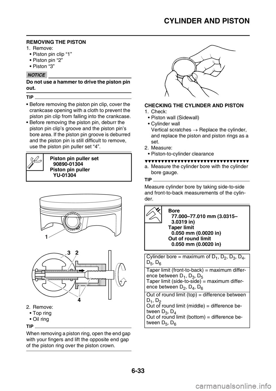
EAS2GBB257REMOVING THE PISTON
1. Remove:
• Piston pin clip “1”
• Piston pin “2”
• Piston “3”
ECA
NOTICE
Do not use a hammer to drive the piston pin
out.
TIP
• Before removing the piston pin clip, cover the
crankcase opening with a cloth to prevent the
piston pin clip from falling into the crankcase.
• Before removing the piston pin, deburr the
piston pin clip’s groove and the piston pin’s
bore area. If the piston pin groove is deburred
and the piston pin is still difficult to remove,
use the piston pin puller set “4”.
2. Remove:
• Top ring
• Oil ring
TIP
When removing a piston ring, open the end gap
with your fingers and lift the opposite end gap
of the piston ring over the piston crown.
EAS2GBB258CHECKING THE CYLINDER AND PISTON
1. Check:
• Piston wall (Sidewall)
• Cylinder wall
Vertical scratches Replace the cylinder,
and replace the piston and piston rings as a
set.
2. Measure:
• Piston-to-cylinder clearance
▼▼▼▼▼▼▼▼▼▼▼▼▼▼▼▼▼▼▼▼▼▼▼▼▼▼▼▼▼▼▼▼
a. Measure the cylinder bore with the cylinder
bore gauge.
TIP
Measure cylinder bore by taking side-to-side
and front-to-back measurements of the cylin-
der. Piston pin puller set
90890-01304
Piston pin puller
YU-01304
1
Bore
77.000–77.010 mm (3.0315–
3.0319 in)
Taper limit
0.050 mm (0.0020 in)
Out of round limit
0.050 mm (0.0020 in)
Cylinder bore = maximum of D
1, D2, D3, D4,
D
5, D6
Taper limit (front-to-back) = maximum differ-
ence between D
1, D3, D5Taper limit (side-to-side) = maximum differ-
ence between D
2, D4, D6
Out of round limit (top) = difference between
D
1, D2Out of round limit (middle) = difference be-
tween D
3, D4Out of round limit (bottom) = difference be-
tween D
5, D6
Page 263 of 432

CYLINDER AND PISTON
6-34
b. If out of specification, rebore or replace the
cylinder, and replace the piston and the pis-
ton rings as a set.
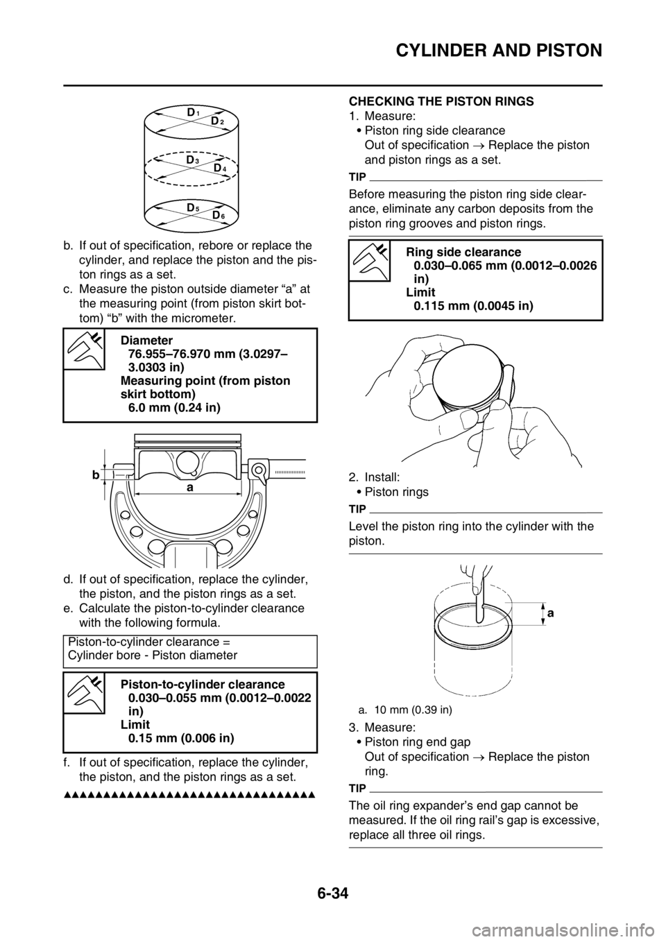
c. Measure the piston outside diameter “a” at
the measuring point (from piston skirt bot-
tom) “b” with the micrometer.
d. If out of specification, replace the cylinder,
the piston, and the piston rings as a set.
e. Calculate the piston-to-cylinder clearance
with the following formula.
f. If out of specification, replace the cylinder,
the piston, and the piston rings as a set.
▲▲▲▲▲▲▲▲▲▲▲▲▲▲▲▲▲▲▲▲▲▲▲▲▲▲▲▲▲▲▲▲
EAS2GBB259CHECKING THE PISTON RINGS
1. Measure:
• Piston ring side clearance
Out of specification Replace the piston
and piston rings as a set.
TIP
Before measuring the piston ring side clear-
ance, eliminate any carbon deposits from the
piston ring grooves and piston rings.
2. Install:
• Piston rings
TIP
Level the piston ring into the cylinder with the
piston.
3. Measure:
• Piston ring end gap
Out of specification Replace the piston
ring.
TIP
The oil ring expander’s end gap cannot be
measured. If the oil ring rail’s gap is excessive,
replace all three oil rings. Diameter
76.955–76.970 mm (3.0297–
3.0303 in)
Measuring point (from piston
skirt bottom)
6.0 mm (0.24 in)
Piston-to-cylinder clearance =
Cylinder bore - Piston diameter
Piston-to-cylinder clearance
0.030–0.055 mm (0.0012–0.0022
in)
Limit
0.15 mm (0.006 in)
b
a
Ring side clearance
0.030–0.065 mm (0.0012–0.0026
in)
Limit
0.115 mm (0.0045 in)
a. 10 mm (0.39 in)
Page 264 of 432

CYLINDER AND PISTON
6-35
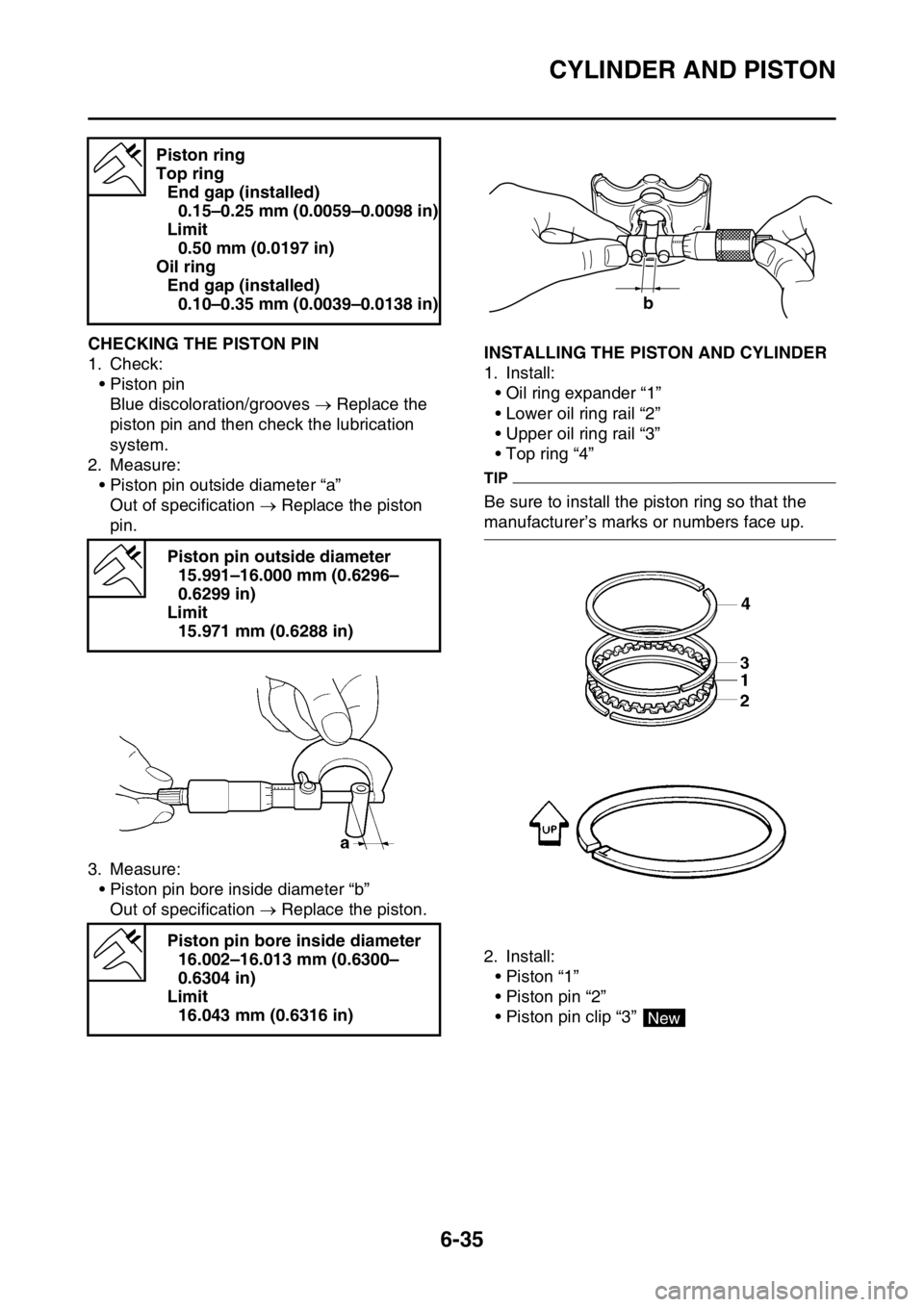
EAS2GBB260CHECKING THE PISTON PIN
1. Check:
• Piston pin
Blue discoloration/grooves Replace the
piston pin and then check the lubrication
system.
2. Measure:
• Piston pin outside diameter “a”
Out of specification Replace the piston
pin.
3. Measure:
• Piston pin bore inside diameter “b”
Out of specification Replace the piston.EAS2GBB261INSTALLING THE PISTON AND CYLINDER
1. Install:
• Oil ring expander “1”
• Lower oil ring rail “2”
• Upper oil ring rail “3”
• Top ring “4”
TIP
Be sure to install the piston ring so that the
manufacturer’s marks or numbers face up.
2. Install:
• Piston “1”
• Piston pin “2”
• Piston pin clip “3” Piston ring
Top ring
End gap (installed)
0.15–0.25 mm (0.0059–0.0098 in)
Limit
0.50 mm (0.0197 in)
Oil ring
End gap (installed)
0.10–0.35 mm (0.0039–0.0138 in)
Piston pin outside diameter
15.991–16.000 mm (0.6296–
0.6299 in)
Limit
15.971 mm (0.6288 in)
Piston pin bore inside diameter
16.002–16.013 mm (0.6300–
0.6304 in)
Limit
16.043 mm (0.6316 in)
b
4
New
Page 268 of 432

ELECTRIC STARTER
6-39
EAS2GBB263CHECKING THE STARTER MOTOR
1. Check:
•Commutator
Dirt Clean with 600 grit sandpaper.
2. Measure:
• Commutator diameter “a”
Out of specification Replace the starter
motor.
3. Measure:
• Mica undercut “a”
Out of specification Scrape the mica to
the proper measurement with a hacksaw
blade that has been grounded to fit the com-
mutator.
TIP
The mica of the commutator must be undercut
to ensure proper operation of the commutator.
4. Measure:
• Armature assembly resistances (commuta-
tor and insulation)
Out of specification Replace the starter
motor.
▼▼▼▼▼▼▼▼▼▼▼▼▼▼▼▼▼▼▼▼▼▼▼▼▼▼▼▼▼▼▼▼
a. Measure the armature assembly resistanc-
es with the pocket tester.b. If any resistance is out of specification, re-
place the starter motor.
▲▲▲▲▲▲▲▲▲▲▲▲▲▲▲▲▲▲▲▲▲▲▲▲▲▲▲▲▲▲▲▲
5. Measure:
• Brush length “a”
Out of specification Replace the brush
set.
6. Measure:
• Brush spring force
Out of specification Replace the brush
set.
7. Check:
• Gear teeth
Damage/wear Replace the starter motor. Limit
16.6 mm (0.65 in)
Mica undercut (depth)
1.50 mm (0.06 in)
Pocket tester
90890-03112
Analog pocket tester
YU-03112-C
Armature coil
Commutator resistance “1”
0.0189–0.0231
Insulation resistance “2”
Above 1 M
Limit
3.50 mm (0.14 in)
Brush spring force
3.92–5.88 N (400–600 gf, 14.11–
21.17 oz)
Page 276 of 432

CLUTCH
6-47
EAS2GBB276CHECKING THE PRIMARY DRIVEN GEAR
1. Check:
• Primary driven gear
Damage/wear Replace the primary drive
and primary driven gears as a set.
Excessive noise during operation Re-
place the primary drive and primary driven
gears as a set.
EAS2GBB277INSTALLING THE OIL SEAL
1. Install:
• Oil seal “1”
• Washer “2”
• Circlip “3”
TIP
• Apply the lithium-soap-based grease on the
oil seal lip.
• Install the oil seal in parallel with its manufac-
ture's marks or numbers facing inward.
EAS2GBB278INSTALLING THE RIGHT CRANKCASE
COVER
1. Install:
• Dowel pin “1”
• O-ring “2”
• Collar “3”
• Gasket “4”
TIP
Apply the lithium-soap-based grease on the O-
ring.2. Install:
• Right crankcase cover “1”
• Right crankcase cover bolt “2”
TIP
• Apply the engine oil on the impeller shaft end.
• Mesh the impeller shaft gear “3” with primary
drive gear “4”.
• Tighten the right crankcase cover bolts in
stages and in a crisscross pattern.
EAS2GBB279INSTALLING THE CLUTCH
1. Install:
• Push lever shaft “1”
TIP
• Apply the lithium-soap-based grease on the
oil seal lip.
• Before installation, apply the engine oil to the
push lever shaft sliding surface.
New
New
3
2
1
LS
New
New
1
1
3
2
4
LS
Right crankcase cover bolt
10 Nm (1.0 m·kgf, 7.2 ft·lbf)
T R..
3
1
4
E
1
2