Page 25 of 106

Instrument and control functions
4-7
1
2
345
6
7
8
9
10
11
12
all, use extra caution to avoid possi-
ble wheel lock during emergency
braking. Have a Yamaha dealer
check the brake system and electri-
cal circuits as soon as possible.
EAU77001
Traction control system indicator
light “ ”
In normal operation, this indicator light
flashes when traction control has en-
gaged.
When the traction control system has
been turned off (page 3-1), this indica-
tor light will come on.
If the traction control system becomes
disabled while riding, this indicator light
and the engine trouble warning light will
come on.
EAU76411
Quick shift indicator light “ ”
When the key is turned to “ON”, the
quick shift system (page 3-3) turns on
and this indicator light comes on.
If a problem is detected in the quick
shift system, this light will turn off and
the quick shift system will be unavail-
able. Have a Yamaha dealer check the vehicle.
EAU73120
Immobilizer system indicator light
“”
When the key is turned to “OFF” and 30
seconds have passed, the indicator
light will flash steadily to indicate the im-
mobilizer system is enabled. After 24
hours have passed, the indicator light
will stop flashing, however the immobi-
lizer system is still enabled.
The electrical circuit of the indicator
light can be checked by turning the key
to “ON”. The indicator light should
come on for a few seconds, and then
go off.
If the indicator light does not come on
initially when the key is turned to “ON”,
if the indicator light remains on, or if the
indicator light flashes in a pattern (if a
problem is detected in the immobilizer
system, the immobilizer system indica-
tor light will flash in a pattern), have a
Yamaha dealer check the vehicle.TIPIf the immobilizer system indicator light
flashes in the pattern, slowly 5 times
then quickly 2 time
s, this could becaused by transponder interference. If
this occurs, try the following.
1. Make sure there are no other im- mobilizer keys close to the main
switch. Other immobilizer system
keys may cause signal interfer-
ence and prevent the engine from
starting.
2. Use the code re-registering key to start the engine.
3. If the engine starts, turn it off, and try starting the engine with the
standard keys.
4. If one or both of the standard keys do not start the engine, take the
vehicle and all 3 keys to a Yamaha
dealer to have the standard keys
re-registered.
BS2-9-E0.book 7 ページ 2016年9月8日 木曜日 午前11時0分
Page 26 of 106

Instrument and control functions
4-8
1
2
34
5
6
7
8
9
10
11
12
EAU77051
Multi-function meter unit
WARNING
EWA12423
Be sure to stop the vehicle before
making any setting changes to the
multi-function meter unit. Changing
settings while riding can distract the
operator and increase the risk of anaccident.
The multi-function meter unit is equipped with the following:
a speedometer
a tachometer
a clock
a fuel meter
an eco indicator
a transmission gear display
a drive mode display
a TCS display
a multi-function display
TIP
Except when switching to the
brightness control mode or to dis-
play the clock, turn the key to “ON”
before using the “SELECT” and
“RESET” buttons to adjust the
multi-function meter.
To switch the speedometer and
multi-function displays between ki-
lometers and miles, press the “SE-LECT” button for one second.
1. “SELECT” button
2. “RESET” button
2
1
1. Transmission gear display
2. Tachometer
3. Eco indicator “ECO”
4. TCS display
5. Drive mode display
6. Fuel meter
7. Multi-function display
8. Clock
9. Speedometer1
2
4
3
5
6
7
8
9
BS2-9-E0.book 8 ページ 2016年9月8日 木曜日 午前11時0分
Page 27 of 106

Instrument and control functions
4-9
1
2
345
6
7
8
9
10
11
12
Speedometer
The speedometer shows the vehicle’s
traveling speed.
Tachometer
The tachometer allows the rider to
monitor the engine speed and keep it
within the ideal power range.
NOTICE
ECA10032
Do not operate the engine in the ta-
chometer red zone.Red zone: 11250 r/min and above
Clock
The clock uses a 12-hour time system.
When the key is not in the “ON” posi-
tion, the clock can be viewed by push-
ing the “SELECT” button.
To set the clock1. Turn the key to “ON”.2. Push the “SELECT” button and the
“RESET” button for two seconds.
3. When the hour digits start flashing, use the “RESET” button to set the
hours.
4. Push the “SELECT” button, and the minute digits wi ll start flashing.
5. Use the “RESET” button to set the minutes.
6. Push the “SELECT” button to con- firm the settings and start the
clock.
Fuel meter
The fuel meter indicates the amount of
fuel in the fuel tank. The display seg-
ments of the fuel meter disappear from
1. Speedometer
1. Tachometer
2. Tachometer red zone
1
2
1
1. Clock
1
1. Fuel meter
1
BS2-9-E0.book 9 ページ 2016年9月8日 木曜日 午前11時0分
Page 28 of 106
 towards “E” (empty) as the fuel
level decreases. When the last seg-
ment starts flashing, refuel as soon as
possible.")
Instrument and control functions
4-10
1
2
34
5
6
7
8
9
10
11
12 “F” (full) towards “E” (empty) as the fuel
level decreases. When the last seg-
ment starts flashing, refuel as soon as
possible.
TIPIf a problem is detected in the electrical
ciruit, the fuel level segments and “ ”
will flash repeatedly. If this occurs, havea Yamaha dealer check vehicle.
Eco indicator
This indicator comes on when the vehi-
cle is being operated in an environmen-
tally friendly, fuel-efficient manner. The
indicator goes off when the vehicle is
stopped.
TIPConsider the following tips to reduce
fuel consumption:
Avoid high engine speeds during
acceleration.
Travel at a constant speed.
Select the transmission gear that
is appropriate for the vehiclespeed.
Transmission gear display
This display shows the selected gear.
The neutral position is indicated by “ ”
and by the neutral indicator light. Drive mode display
This display indicates which drive
mode has been selected: “STD”, “A” or
“B”. For more details on the modes and
on how to select them, see page 3-1.
TCS display
1. Eco indicator “ECO”
1
1. Transmission gear display
2. Neutral indicator light “ ”1
2
1. Drive mode display
1. TCS display
11
BS2-9-E0.book 10 ページ 2016年9月8日 木曜日 午前11時0分
Page 29 of 106

Instrument and control functions
4-11
1
2
345
6
7
8
9
10
11
12
This display indicates which traction
control system setting has been select-
ed: “1”, “2” or “OFF”. For more details
on the TCS settings and on how to se-
lect them, see page 3-1.
Multi-function display
The multi-function display is equipped
with the following:
an odometer
two tripmeters
a fuel reserve tripmeter
an instantaneous fuel consump-
tion display
an average fuel consumption dis-
play
a coolant temperature display
an air intake temperature display
a brightness control display
TIP
The odometer will lock at 999999
and cannot be reset.
The tripmeters will lock at 9999.9but can be manually reset.
Push the “SELECT” button to switch
the display between the instantaneous
fuel consumption mode “km/L” or “L/
100 km”, average fuel consumption
mode “AVE_ _._ km/L” or “AVE_ _._ L/
100 km”, coolant temperature mode
“ C”, air intake temperature mode “Air_
_ C”, odometer mode “ODO”, and trip-
meter modes “TRIP 1” and “TRIP 2” in
the following order:
km/L or L/100 km AVE_ _._ km/L or
AVE_ _._ L/100 km C Air_ _ C
ODO TRIP 1 TRIP 2
When the display units have been set
to miles:
km/L, L/100 km or MPG AVE_ _._
km/L, AVE_ _._ L/100 km or AVE_ _._
MPG C Air_ _ C ODO
TRIP 1 TRIP 2
TIPPush the “RESET” button to switch thedisplay in the reverse order.
If the last segment of the fuel meter
starts flashing, the display automatical-
ly changes to the fuel reserve tripmeter
mode “F-TRIP” and starts counting the
distance traveled from that point. In this
case, push the “SELECT” button to
switch the display in the following order:
F-TRIP km/L or L/100 km AVE_
_._ km/L or AVE_ _._ L/100 km C
Air_ _ C ODO TRIP 1 TRIP
2 F-TRIP
When the display units have been set
to miles:
F-TRIP km/L, L/100 km or MPG
AVE_ _._ km/L, AVE_ _._ L/100 km or
AVE_ _._ MPG C Air_ _ C
ODO TRIP 1 TRIP 2 F-TRIPTIP
To reset a tripmeter, select it by
pushing the “SELECT” button, and
1. Multi-function display
1
BS2-9-E0.book 11 ページ 2016年9月8日 木曜日 午前11時0分
Page 30 of 106

Instrument and control functions
4-12
1
2
34
5
6
7
8
9
10
11
12 then push the “RESET” button for
one second.
If you do not reset the fuel reserve
tripmeter manually, it resets auto-
matically and disappears after re-fueling and traveling 5 km (3 mi).
Instantaneous fuel consumption
mode
The instantaneous fuel consumption
display can be set to either “km/L”, “L/
100 km” or “MPG” (when the display
units have been set to miles).
“km/L”: The distance that can be
traveled on 1.0 L of fuel under the
current riding condi tions is shown.
“L/100 km”: The amount of fuel necessary to travel 100 km under
the current riding conditions is
shown.
“MPG”: The distance that can be
traveled on 1.0 Imp.gal of fuel un-
der the current riding conditions is
shown.
To switch between the instantaneous
fuel consumption display settings, push
the “SELECT” button for one second.
TIPIf traveling at speeds under 20 km/h (12mi/h), “_ _._” is displayed.
Average fuel consumption mode
This display shows the average fuel consumption since it was last reset.
The average fuel consumption display
can be set to either “AVE_ _._ km/L”,
“AVE_ _._ L/100 km” or “AVE_ _._
MPG” (when the display units have
been set to miles:).
“AVE_ _._ km/L”: The average dis-
tance that can be traveled on 1.0 L
of fuel is shown.
“AVE_ _._ L/100 km”: The average
amount of fuel necessary to travel
100 km is shown.
“AVE_ _._ MPG”: The average
distance that can be traveled on
1.0 Imp.gal of fuel is shown.
To switch between the average fuel
consumption display settings, push the
“SELECT” button for one second.
To reset the average fuel consumption,
push the “RESET” button for one sec-
ond.
TIPAfter resetting the average fuel con-
sumption, “_ _._” will be shown until thevehicle has traveled 1 km (0.6 mi).
1. Instantaneous fuel consumption display
1
1. Average fuel consumption display
1
BS2-9-E0.book 12 ページ 2016年9月8日 木曜日 午前11時0分
Page 31 of 106

Instrument and control functions
4-13
1
2
345
6
7
8
9
10
11
12
Coolant temperature mode
This display shows the coolant temper-
ature from 40
C to 116 C in 1 C incre-
ments.
If the message “HI” flashes, stop the
vehicle, then stop the engine, and let
the engine cool. (See page 7-40.)
TIP
When the coolant temperature is
below 40 C, “Lo” will be displayed.
The coolant temperature varies
with changes in the weather andengine load. Air intake temperature mode
The air intake temperature display indi-
cates the temperature of the air drawn
into the air filter case.
This display shows the air intake tem-
perature from –9
C to 99 C in 1 C in-
crements.
TIP
–9 C will be displayed even if the
air intake temperature falls below
–9 C.
The air intake temperature may
vary from the ambient tempera-ture. Brightness control mode
The brightness of the multi-function
meter unit panel can be adjusted.
To adjust the brightness
1. Turn the key to “OFF”.
2. While pushing the “SELECT” but-
ton, turn the key to “ON” and con-
tinue pushing the button until the
display switches to the brightness
control mode.
3. Push the “RESET” button to set the brightness level.
4. Push the “SELECT” button to con- firm the selected brightness level
and exit the brightness control
mode.
1. Coolant temperature display
1
1. Air intake temperature display
1
1. Brightness level display
1
BS2-9-E0.book 13 ページ 2016年9月8日 木曜日 午前11時0分
Page 32 of 106

Instrument and control functions
4-14
1
2
34
5
6
7
8
9
10
11
12
EAU12822
Clutch leverThe clutch lever is located on the left
side of the handlebar. To disengage
the clutch, pull the lever toward the
handlebar grip. To engage the clutch,
release the lever. The lever should be
pulled rapidly and released slowly for
smooth clutch operation.
The clutch lever is equipped with a
clutch switch, which is part of the igni-
tion circuit cut-off system. (See
page 4-26.)
EAU76301
Shift pedalThe shift pedal is located on the left
side of the motorcycle and is used in
combination with the clutch lever when
shifting the gears of the 6-speed con-
stant-mesh transmission.
When the quick shift system is turned
on, the shift switch senses shift pedal
movement and allows for upshifting
without operating the clutch lever. (See
page 3-3.)
EAU26825
Brake leverThe brake lever is located on the right
side of the handlebar. To apply the front
brake, pull the lever toward the throttle
grip.
The brake lever is equipped with a
brake lever position adjusting dial. To
adjust the distance between the brake
lever and the throttle grip, turn the ad-
justing dial while holding the lever
pushed away from the throttle grip.
Make sure that the appropriate setting
on the adjusting dial is aligned with the
1. Clutch lever
1
1. Shift pedal
2. Shift switch
12
1. Brake lever
2. Distance between brake lever and throttle grip
3. Brake lever position adjusting dial
4. “ ” mark
5 4 3 2 1
1
2
43
BS2-9-E0.book 14 ページ 2016年9月8日 木曜日 午前11時0分
 1
1 2
2 3
3 4
4 5
5 6
6 7
7 8
8 9
9 10
10 11
11 12
12 13
13 14
14 15
15 16
16 17
17 18
18 19
19 20
20 21
21 22
22 23
23 24
24 25
25 26
26 27
27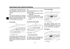 28
28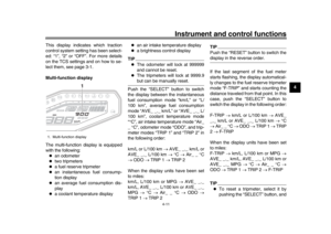 29
29 30
30 31
31 32
32 33
33 34
34 35
35 36
36 37
37 38
38 39
39 40
40 41
41 42
42 43
43 44
44 45
45 46
46 47
47 48
48 49
49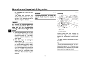 50
50 51
51 52
52 53
53 54
54 55
55 56
56 57
57 58
58 59
59 60
60 61
61 62
62 63
63 64
64 65
65 66
66 67
67 68
68 69
69 70
70 71
71 72
72 73
73 74
74 75
75 76
76 77
77 78
78 79
79 80
80 81
81 82
82 83
83 84
84 85
85 86
86 87
87 88
88 89
89 90
90 91
91 92
92 93
93 94
94 95
95 96
96 97
97 98
98 99
99 100
100 101
101 102
102 103
103 104
104 105
105