Page 81 of 102
![YAMAHA MT-07 2017 Owners Manual Periodic maintenance an d a djustment
6-32
6
key is turne
d to “OFF”, then
connect the positive lea d b efore
connectin g the ne gative lea d.
[ECA16841]
4. After installation, make sure that
the](/manual-img/51/50803/w960_50803-80.png "YAMAHA MT-07 2017 Owners Manual Periodic maintenance an d a djustment
6-32
6
key is turne
d to “OFF”, then
connect the positive lea d b efore
connectin g the ne gative lea d.
[ECA16841]
4. After installation, make sure that
the")
Periodic maintenance an d a djustment
6-32
6
key is turne
d to “OFF”, then
connect the positive lea d b efore
connectin g the ne gative lea d.
[ECA16841]
4. After installation, make sure that
the battery leads are properly con-
nected to the battery terminals.NOTICE
ECA16531
Always keep the b attery charged .
Storin g a dischar ged battery can
cause permanent b attery damag e.
EAU59872
Replacin g the fusesThe main fuse and the fuse boxes,
which contain the fuses for the individ-
ual circuits, are located under the rider
seat. (See page 3-19.)TIPTo access the main fuse, remove the
starter relay cover as shown.
If a fuse is blown, replace it as follows.
1. Turn the key to “OFF” and turn off the electrical circuit in question.
2. Remove the blown fuse, and then install a new fuse of the specified
amperage. WARNING! Do not
use a fuse of a hi gher ampera ge
1. Starter relay cover
2. Fuse box
3. Spare main fuse
4. Main fuse
2
3
4
1
1. Ignition fuse
2. Signaling system fuse
3. Headlight fuse
4. Backup fuse 2 (for ECU)
5. Backup fuse (for clock and immobilizer sys-
tem)
6. Radiator fan motor fuse
7. ABS solenoid fuse
8. ABS motor fuse
9. Parking lighting fuse
10.Auxiliary fuse
11.ABS control unit fuse
12.Spare fuse
7
8
9
10
11
1
2
3
4
5
61212
UBU2E0E0.book Page 32 Friday, September 9, 2016 9:23 AM
Page 82 of 102
![YAMAHA MT-07 2017 Owners Manual Periodic maintenance an d a djustment
6-33
6 ratin
g than recommen ded to
avoi d causin g extensive d am-
a g e to the electrical system an d
possi bly a fire.
[EWA15132]
3. Turn the key to “ON”](/manual-img/51/50803/w960_50803-81.png "YAMAHA MT-07 2017 Owners Manual Periodic maintenance an d a djustment
6-33
6 ratin
g than recommen ded to
avoi d causin g extensive d am-
a g e to the electrical system an d
possi bly a fire.
[EWA15132]
3. Turn the key to “ON”")
Periodic maintenance an d a djustment
6-33
6 ratin
g than recommen ded to
avoi d causin g extensive d am-
a g e to the electrical system an d
possi bly a fire.
[EWA15132]
3. Turn the key to “ON” and turn on
the electrical circuit in question to
check if the device operates.
4. If the fuse immediately blows again, have a Yamaha dealer
check the electrical system.
EAU59881
Replacin g the hea dlig ht bul bThis model is equipped with a halogen
bulb headlight. If the headlight bulb
burns out, replace it as follows.NOTICE
ECA10651
Take care not to damag e the follow-
in g parts:
Hea dlig ht bul b
Do not touch the glass part of
the hea dlig ht bul b to keep it free
from oil, otherwise the transpar-
ency of the glass, the luminosity
of the b ulb, an d the b ulb life will
b e ad versely affecte d. Thor-
ou ghly clean off any d irt and fin-
g erprints on the hea dlig ht bul b
usin g a cloth moistene d with al-
cohol or thinner.
Hea dlig ht lens
Do not affix any type of tinte d
film or stickers to the hea dlig ht
lens.
Do not use a hea dlig ht bul b of a
wattag e higher than specifie d.
Specifie d fuses:
Main fuse: 30.0 A
Auxiliary fuse:
2.0 A
Headlight fuse: 15.0 A
Signaling system fuse: 10.0 A
Ignition fuse:
10.0 A
Parking lighting fuse: 7.5 A
Radiator fan motor fuse: 10.0 A
ABS motor fuse:
30.0 A
ABS solenoid fuse: 20.0 A
ABS control unit fuse: 7.5 A
Backup fuse:
7.5 A
Backup fuse 2: 10.0 A
UBU2E0E0.book Page 33 Friday, September 9, 2016 9:23 AM
Page 83 of 102
Periodic maintenance an d a djustment
6-34
6
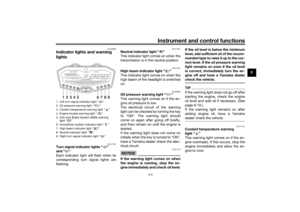
1. Remove the headlight unit by re-
moving the bolt and washer on
each side. 2. Disconnect the headlight coupler,
and then remove the headlight
bulb cover.
3. Unhook the headlight bulb holder, then remove the burnt-out bulb. 4. Place a new headlight bulb into
position, then secure it with the
bulb holder.
5. Install the headlight bulb cover, then connect the coupler.
6. Install the headlight unit as shown, and then install the washer and
bolt on each side.
1. Do not touch the glass part of the bulb.
1. Bolt and washer1
1. Bolt and washer
1. Headlight coupler
2. Headlight bulb cover
11
2
1. Headlight bulb holder
2. Headlight bulb
2
1
UBU2E0E0.book Page 34 Friday, September 9, 2016 9:23 AM
Page 84 of 102
Periodic maintenance an d a djustment
6-35
6 7. Have a Yamaha dealer adjust the
headlight beam if necessary.
EAU46405
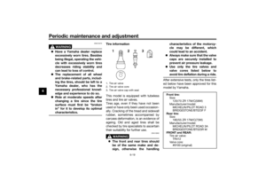
Replacin g the auxiliary li ght
b ul bIf the auxiliary light bulb burns out, re-
place it as follows.
1. Remove the headlight unit. (See page 6-33.)
2. Remove the auxiliary light bulb socket (together with the bulb) by
turning it counterclockwise.
3. Remove the burnt-out bulb by pulling it out of the socket. 4. Insert a new bulb into the socket.
5. Install the socket (together with
the bulb) by turning it clockwise.
6. Install the headlight unit.1. Auxiliary light bulb socket
1
1. Auxiliary light bulb
1
UBU2E0E0.book Page 35 Friday, September 9, 2016 9:23 AM
Page 85 of 102
Periodic maintenance an d a djustment
6-36
6
EAU70540
Brake/tail li ghtThis model is equipped with an LED-
type brake/tail light.
If the brake/tail light does not come on,
have a Yamaha dealer check it.
EAU24205
Replacin g a turn sig nal light
b ul b1. Remove the turn signal light lens
by removing the screw.
2. Remove the burnt-out bulb by pushing it in and turning it coun-
terclockwise. 3. Insert a new bulb into the socket,
push it in, and then turn it clock-
wise until it stops.
4. Install the lens by installing the screw. NOTICE: Do not over-
ti ghten the screw, otherwise the
lens may break.
[ECA11192]
1. Turn signal light lens
2. Screw
1
2
1. Turn signal light bulb
1
UBU2E0E0.book Page 36 Friday, September 9, 2016 9:23 AM
Page 86 of 102

Periodic maintenance an d a djustment
6-37
6
EAU59890
Replacin g the license plate
li g ht bul b1. Remove the license plate light unit
by removing the nuts, washers
and collars, and then remove the
license plate light bulb socket (to-
gether with the bulb) by pulling it
out.
2. Remove the burnt-out bulb by pulling it out. 3. Insert a new bulb into the socket.
4. Install the socket (together with
the bulb) by pushing it in, and then
install the license plate light unit by
installing the collars, washers and
nuts.
EAU67131
Supportin g the motorcycleSince this model is not equipped with a
centerstand, use maintenance stands
when removing the front or rear wheel
or when performing other maintenance
that requires the motorcycle to stand
up right.
Check that the motorcycle is in a stable
and level position before starting any
maintenance.
1. License plate light unit
2. Collar
3. Washer
4. Nut
5. License plate light bulb socket
1
22
53
4
3
4
1. License plate light bulb
1
1. Maintenance stand (example)
1
UBU2E0E0.book Page 37 Friday, September 9, 2016 9:23 AM
Page 87 of 102

Periodic maintenance an d a djustment
6-38
6
EAU25872
Trou bleshootin gAlthough Yamaha motorcycles receive
a thorough inspection before shipment
from the factory, trouble may occur
during operation. Any problem in the
fuel, compression, or ignition systems,
for example, can cause poor starting
and loss of power.
The following troubleshooting charts
represent quick and easy procedures
for checking these vital systems your-
self. However, should your motorcycle
require any repair, take it to a Yamaha
dealer, whose skilled technicians have
the necessary tools, experience, and
know-how to service the motorcycle
properly.
Use only genuine Yamaha replace-
ment parts. Imitation parts may look
like Yamaha parts, but they are often
inferior, have a shorter service life and
can lead to expensive repair bills.
WARNING
EWA15142
When checkin g the fuel system, d o
not smoke, an d make sure there are
no open flames or sparks in the ar-
ea, inclu din g pilot li ghts from water heaters or furnaces. Gasoline or
g
asoline vapors can i gnite or ex-
plo de, causin g severe injury or prop-
erty damag e.
UBU2E0E0.book Page 38 Friday, September 9, 2016 9:23 AM
Page 88 of 102

Periodic maintenance an d a djustment
6-39
6
EAU42365
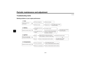
Trou bleshootin g chartsStartin g pro blems or poor en gine performance
Check the fuel level in
the fuel tank.1. Fuel
There is enough fuel.
There is no fuel.
Check the battery.
Supply fuel.
The engine does not start.
Check the battery.
Remove the spark plugs
and check the electrodes.3. Ignition
Wipe off with a dry cloth and correct the
spark plug gaps, or replace the spark plugs.
Have a Yamaha dealer check the vehicle.
Operate the electric starter.4. Compression
There is compression.
There is no compression.
The engine does not start.
Have a Yamaha dealer check the vehicle.Have a Yamaha dealer check the vehicle.
The engine does not start.
Check the compression.
Operate the electric starter.2. Battery
The engine turns over
quickly.
The engine turns over
slowly.
The engine does not start.
Check the ignition.
The battery is good.Check the battery lead connections,
and have a Yamaha dealer charge
the battery if necessary.
DryWet
Operate the electric starter.
UBU2E0E0.book Page 39 Friday, September 9, 2016 9:23 AM